Thingiverse
QIDI X-one Glass Bed by gwj3
by Thingiverse
Last crawled date: 3 years ago
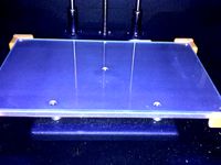
These hold downs slide into place and can be moved around at will. The extruder and fan duct remain clear as the machine goes through the Homing Cycle, Level Cycle and Start Cycle. The plastic fan duct only has about 1/16th of an inch clearance. Consider filing or sanding just the Tip of the Swing Arm Top to add more clearance. If you use a custom duct you will need to do some testing to make sure you have clearance.
Revisions: The Slide Brace part as been revised to allow for more clearance. As the PLA Slide Brace "Breaks-IN" / Bends / Warps it still works fine but a slight adjustment was necessary. Let me know if you ever print this and out of what material. PLA works fine but ABS may be a better choice. The old Slide Brace STL & STEP files were deleted and replaced with a new file name with R1 on the end of the name.
Possible Issues:
The heatbed may cause the PLA Slide Brace Part to become soft and bend too much. I use a 0.19 inch thick cork sheet on the bottom for insulation so the heat is blocked. ABS filament may be a better choice for the Slide Brace Part. I was too lazy to take off the cork just to test this. Please report your results.
It is very possible to run the extruder tip into the clamps. Warning / Disclaimer; You could damage your machine by running the extruder into the clamps. If you download this design you will agree that any damage caused while using these hold downs is completely your responsibility. I can’t think of all the ways you can run the extruder into these hold downs but I offer a few things to think about and feel free to add to the list. The extruder tip could hit the hold downs if you jog the machine into them or start the homing sequence with the extruder lined up (on either side) for a head on collision and etc. so care must be used but I think with a bit of thought everyone should be able to handle that. I suggest the first few times you run the automatic sequence for Start - Home or Level that you keep your finger on the On/Off switch in case you need to do a quick stop. The safest technique / habit is to always have the Z Axis height a few steps lower than the Home Position before activating any automatic sequences. (i.e.: Start – Level or Home)
Updates:
My clamp design failed on a tall vertical print. About 3 hours into the print the glass plate slipped.
Good News: After more testing, I determined that I simply needed to tighten the clamps down a bit more. I also smeared about a dozen glue stick marks on the bottom of the glass in hopes that this would act as a non skid surface. The plate removes from the bed without any indication of the glue stick so I really don't think the glue stick did anything. I still think 3 clamps is all that is needed but a 4th clamp would be even better I guess. I still like the idea of adding some sort of non skid to the blue build tac. If anyone has suggestions on this please add a comment. BTW: My Build Tac is very smooth and almost slick.
I have printed many parts now and this hold down design continues to work perfectly.
Printing Information: I used PLA at 100% Fill Density. ABS may be a better choice but the PLA does work for me.
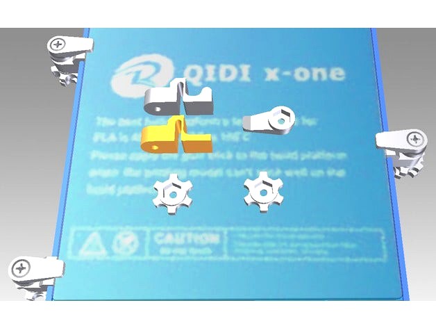
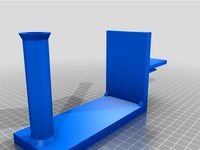
Parts To Print: Note: The correct orientation to lay out the parts for printing are shown in the CAD photo where all the parts are laying on the glass bed. The individual STL photos are not all in the proper orientation for printing. Important It may look better to print the slide base in a different orientation but the part will loose strustural strength if you print it wrong.
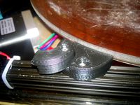
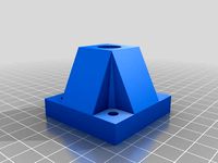
Slide Base - Quantity of 3 – Use a small round file to clean out the hole. Note: This hole is designed to be a loose fit. The file named “Slide Base” is for Heatbeds with no insulation on the bottom. I request that you post a message and let everyone know if this Slide Base worked for you. I have insulation on my Bed so I did not test this standard Slide Base. I don’t know if the fit will be correct or if heat will cause issues.
Slide Base Modified – Shown in the CAD photos in Yellow. This file is named “Slide Base Modified” and is for those that use 0.19 inch thick cork to insulate the bottom of the heatbed. Use a small round file to clean out the hole. Note: This hole is designed to be a loose fit.
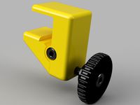
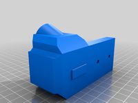
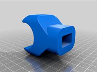
Swing Arm - Quantity of 3– After printing; screw a 6-32 Bolt down tight onto the Nut. Also; file or sand just the top tip to add a bit more clearance from the plastic fan duct.
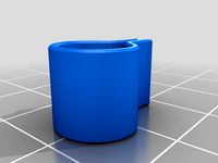
Adjustment Wheel - Quantity of 6 – Consider using Loctite Super Glue Gel Control on the Wheel Nuts.
Fasteners: Bolt: #6-32 1 1/4inch & 3 Nuts - The 1 ¼ inch bolt length works for a glass thickness of 1/8 inch or less. If you use thicker glass you will probably need a 1 ½ inch length bolt.
Instructions for using the clamps:
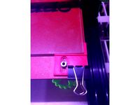
These Hold Downs require a binding action to work. The CAD drawings show all parts in a perfect vertical alignment but in reality the Slide Base bolt hole is designed oversized so that the Swing Arm will tilt back allowing the required binding action. See the photo.
To set the clamp; push up from the bottom and swing the arm into position. Press down on the tip of the Swing Arm onto the glass and tighten the top adjustment wheel to a light pressure position now lock the top wheel in place by tightening the bottom wheel. Do not over tighten! The Slide Brace will start to bend if the adjustment wheels are over tightened. Important
Note: There will be a period of break-in because the PLA Slide Base part will bend a bit at the 90 degree point but then stablize.
Also; I do not use a shim to compensate for the extra height of the .125" glass thickness however I did notice that the AFT SCREW was not installed on the silver part that holds the Z Axis Screw in position. I intalled the scew from the extra parts that came with the machine and this screw head acts just like a shim would. Another user said he does not use a shim either but simply tightens the bed all the way down and then does a new Level sequence and adjust the bed which also worked for me.
Release the clamp by simply turning the Swing Arm off to the side. As the PLA settles it will become a bit bent under the bed and therefore you will need to readjust the clamps.
I have include both STEP and STL files. No tip is expected but I will accept them. Thanks!
If you decide to purchase glass and want a high quality type which may not be necessary. I recommend a company on eBay named go3dprint.https://www.ebay.com/usr/go3dprint I have no affiliation except that I am highly satisfied with my purchase and service after the sale.
Revisions: The Slide Brace part as been revised to allow for more clearance. As the PLA Slide Brace "Breaks-IN" / Bends / Warps it still works fine but a slight adjustment was necessary. Let me know if you ever print this and out of what material. PLA works fine but ABS may be a better choice. The old Slide Brace STL & STEP files were deleted and replaced with a new file name with R1 on the end of the name.
Possible Issues:
The heatbed may cause the PLA Slide Brace Part to become soft and bend too much. I use a 0.19 inch thick cork sheet on the bottom for insulation so the heat is blocked. ABS filament may be a better choice for the Slide Brace Part. I was too lazy to take off the cork just to test this. Please report your results.
It is very possible to run the extruder tip into the clamps. Warning / Disclaimer; You could damage your machine by running the extruder into the clamps. If you download this design you will agree that any damage caused while using these hold downs is completely your responsibility. I can’t think of all the ways you can run the extruder into these hold downs but I offer a few things to think about and feel free to add to the list. The extruder tip could hit the hold downs if you jog the machine into them or start the homing sequence with the extruder lined up (on either side) for a head on collision and etc. so care must be used but I think with a bit of thought everyone should be able to handle that. I suggest the first few times you run the automatic sequence for Start - Home or Level that you keep your finger on the On/Off switch in case you need to do a quick stop. The safest technique / habit is to always have the Z Axis height a few steps lower than the Home Position before activating any automatic sequences. (i.e.: Start – Level or Home)
Updates:
My clamp design failed on a tall vertical print. About 3 hours into the print the glass plate slipped.
Good News: After more testing, I determined that I simply needed to tighten the clamps down a bit more. I also smeared about a dozen glue stick marks on the bottom of the glass in hopes that this would act as a non skid surface. The plate removes from the bed without any indication of the glue stick so I really don't think the glue stick did anything. I still think 3 clamps is all that is needed but a 4th clamp would be even better I guess. I still like the idea of adding some sort of non skid to the blue build tac. If anyone has suggestions on this please add a comment. BTW: My Build Tac is very smooth and almost slick.
I have printed many parts now and this hold down design continues to work perfectly.
Printing Information: I used PLA at 100% Fill Density. ABS may be a better choice but the PLA does work for me.
Parts To Print: Note: The correct orientation to lay out the parts for printing are shown in the CAD photo where all the parts are laying on the glass bed. The individual STL photos are not all in the proper orientation for printing. Important It may look better to print the slide base in a different orientation but the part will loose strustural strength if you print it wrong.
Slide Base - Quantity of 3 – Use a small round file to clean out the hole. Note: This hole is designed to be a loose fit. The file named “Slide Base” is for Heatbeds with no insulation on the bottom. I request that you post a message and let everyone know if this Slide Base worked for you. I have insulation on my Bed so I did not test this standard Slide Base. I don’t know if the fit will be correct or if heat will cause issues.
Slide Base Modified – Shown in the CAD photos in Yellow. This file is named “Slide Base Modified” and is for those that use 0.19 inch thick cork to insulate the bottom of the heatbed. Use a small round file to clean out the hole. Note: This hole is designed to be a loose fit.
Swing Arm - Quantity of 3– After printing; screw a 6-32 Bolt down tight onto the Nut. Also; file or sand just the top tip to add a bit more clearance from the plastic fan duct.
Adjustment Wheel - Quantity of 6 – Consider using Loctite Super Glue Gel Control on the Wheel Nuts.
Fasteners: Bolt: #6-32 1 1/4inch & 3 Nuts - The 1 ¼ inch bolt length works for a glass thickness of 1/8 inch or less. If you use thicker glass you will probably need a 1 ½ inch length bolt.
Instructions for using the clamps:
These Hold Downs require a binding action to work. The CAD drawings show all parts in a perfect vertical alignment but in reality the Slide Base bolt hole is designed oversized so that the Swing Arm will tilt back allowing the required binding action. See the photo.
To set the clamp; push up from the bottom and swing the arm into position. Press down on the tip of the Swing Arm onto the glass and tighten the top adjustment wheel to a light pressure position now lock the top wheel in place by tightening the bottom wheel. Do not over tighten! The Slide Brace will start to bend if the adjustment wheels are over tightened. Important
Note: There will be a period of break-in because the PLA Slide Base part will bend a bit at the 90 degree point but then stablize.
Also; I do not use a shim to compensate for the extra height of the .125" glass thickness however I did notice that the AFT SCREW was not installed on the silver part that holds the Z Axis Screw in position. I intalled the scew from the extra parts that came with the machine and this screw head acts just like a shim would. Another user said he does not use a shim either but simply tightens the bed all the way down and then does a new Level sequence and adjust the bed which also worked for me.
Release the clamp by simply turning the Swing Arm off to the side. As the PLA settles it will become a bit bent under the bed and therefore you will need to readjust the clamps.
I have include both STEP and STL files. No tip is expected but I will accept them. Thanks!
If you decide to purchase glass and want a high quality type which may not be necessary. I recommend a company on eBay named go3dprint.https://www.ebay.com/usr/go3dprint I have no affiliation except that I am highly satisfied with my purchase and service after the sale.
Similar models
thingiverse
free
Glass Bed Clamp
...ge is the printing material and thickness of the hold down.
if you need a different jaw clearance, leave a note in the comments.
thingiverse
free
Tevo Tornado Glass Bed Tensioner by Sking296
...nder clips on the front because the bolts for the bed does not hold these secure enough when the printer is printing small areas.
thingiverse
free

3D Printing bed brace
...use, they can be stored together with one brace attracting and attaching (effectively snapping onto) to the next brace perfectly.
thingiverse
free
Kossel Bed Clamp with Swinging Arm by AlbertP
...mm (3 -0.5 for tolerance) so it properly clamps down the bed. if you need a specific size please let me know and i'll add it.
thingiverse
free

Edge Clips Corner Clips by Monkeyswithguns
...to help with the pressure of holding the glass. the ones with the hole are for my borosilicate glass that is 11.75 inches square.
thingiverse
free
D9 Z-Axis-Stabilizing Brackets
... top bracket. double check for squareness and adjust accordingly.
i will get round to uploading some photos soon.
happy printing.
thingiverse
free

Da Vinci MK3 heat bed and 3mm glass clamp and brace by resago
...e permanent solution.
so you can use either the clamps or the braces.
new addition: z-stop.
i have included the source files.
thingiverse
free

Folger Tech FT-5 Glass Clamp by snowcapjr
...s you to clamp it down (with a couple screws, i used m4 hex head and tapped the hole)
it's low profile and works pretty well.
thingiverse
free
Screw Down Lamp Base by waagstrom
...ngiverse
i found a swing arm lamp in the trash without a clamp base, i decided to screw it down to a workbench using this model.
thingiverse
free
Bed clamp by ArjanKarman
...needed something to hold the glass firmly to the heatbed so i made this simple clamp. i use 4 of them to hold the glass in place.
Qidi
thingiverse
free

Qidi XMAX Spool Clamp
...qidi xmax spool clamp
thingiverse
a simple spool clamp for qidi tech xmax or xplus spool holder(30mm diameter).
thingiverse
free
QIDI Upper spool holder by Shibatam
...qidi upper spool holder by shibatam
thingiverse
upper spool holder for qidi.
use this when the back space is narrow.
thingiverse
free

Qidi Z axis brace by mjgrundmann
...qidi z axis brace by mjgrundmann
thingiverse
used to stiffen up the z axis guide rods on a qidi tech i.
thingiverse
free
DEROULEUR BOBINE QIDI by bil26
...i by bil26
thingiverse
bonjour,
c'est un montage pour imprimante qidi xmax .
montage avec 2 x roulements 6002.
cordialement,
thingiverse
free
QIDI Glass Bed Clips by ChrisX35
...idi glass bed clips by chrisx35
thingiverse
qidi glass bed upgrade.
new clips are here https://www.thingiverse.com/thing:2480107
thingiverse
free

Bed level QIDI - Microsoft LifeCam by lemacs
...bed level qidi - microsoft lifecam by lemacs
thingiverse
bed level camera mount for qidi - microsoft lifecam
thingiverse
free

Qidi X-One cooler duct by rpagyc
...qidi x-one cooler duct by rpagyc
thingiverse
extruder cooling duct for the qidi tech x-one
thingiverse
free
Qidi Tech PTFE adapter by sewallman
...h ptfe adapter by sewallman
thingiverse
adapter for a 6mm ptfe tube to fit ontop the qidi tech xmax/xplus/imates extruder cover.
thingiverse
free

QIDI Shadow filter plug by shifter
... by shifter
thingiverse
this is a cap/plug for the qidi tech shadow 5.5s. to cover the spot where the pointless air filter goes.
thingiverse
free

QIDI Door Latch by TobyC84
...i created for the qidi printer. it holds the door open while you print pla or while you remove a print from the print bed! enjoy!
Bed
3ddd
$1

bed
...bed
3ddd
bed , постельное белье
bed
3ddd
$1

bed
...bed
3ddd
bed , постельное белье
bed
3ddd
$1
bed
...bed
3ddd
bed , постельное белье
bed
3ddd
$1
bed
...bed
3ddd
bed , постельное белье
bed
3ddd
$1

bed
...bed
3ddd
bed , постельное белье
bed
3ddd
$1

bed
...bed
3ddd
bed , постельное белье
bed
3ddd
free
bed
...bed
3ddd
bed , постельное белье
bed
3ddd
free

bed
...bed
3ddd
bed , постельное белье
bed
3ddd
$1
Bed
...bed
3ddd
bed , постельное белье , постель
bed
3d_export
$7
bed adairs bed
...rs bed
3dexport
bed adairs bed in modern style. if you want a smoother surface, please turn on turbosmooth in the modifier list.
Glass
archibase_planet
free
Glasses
...glasses
archibase planet
glass wine-glass liqueur-glass
glasses- 3d model for interior 3d visualization.
archibase_planet
free

Glass
...archibase planet
glass cocktail glass tall wine glass martini glass
glass - 3d model (*.gsm+*.3ds) for interior 3d visualization.
archibase_planet
free

Glass
...glass
archibase planet
glass wine-glass glass-ware
glass n030209 - 3d model (*.gsm+*.3ds) for interior 3d visualization.
archibase_planet
free

Glass
...glass
archibase planet
glass-ware glass glass ware
glass n141109 - 3d model (*.gsm+*.3ds) for interior 3d visualization.
3d_ocean
$2
Glass
...liquid container low-poly glass nice glass obj r15 water glass
3d model of a beautiful glass. created the model in cinema 4d r15.
archibase_planet
free
Glass
...glass
archibase planet
glass tall wine glass wine-glass
glass n300514 - 3d model (*.gsm+*.3ds) for interior 3d visualization.
archibase_planet
free

Glass
...glass
archibase planet
glass wine-glass tall wine glass
glass n091210 - 3d model (*.gsm+*.3ds) for interior 3d visualization.
archibase_planet
free
Glass
...glass
archibase planet
glass tall wine glass glass-ware
glass n081011 - 3d model (*.gsm+*.3ds) for interior 3d visualization.
3d_ocean
$9

glasses
...glasses
3docean
glasses
max glasses v-ray
archibase_planet
free

Glass
...glass
archibase planet
glass-ware glass
glass - 3d model (*.gsm+*.3ds) for interior 3d visualization.
One
turbosquid
$2
one plus one
... available on turbo squid, the world's leading provider of digital 3d models for visualization, films, television, and games.
3ddd
$1
One
...one
3ddd
стул
офисный стул one
3ddd
free

one
...
palazetti one ,http://palazzetti.ca/index.php/component/virtuemart/seating/armchairs-lounges/one-chair-detail?itemid=0
turbosquid
$35

One A
... available on turbo squid, the world's leading provider of digital 3d models for visualization, films, television, and games.
turbosquid
free
One
... available on turbo squid, the world's leading provider of digital 3d models for visualization, films, television, and games.
3ddd
$1
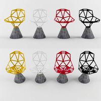
Стул One
...стул one
3ddd
one , magis
кресло magis s.p.a , one
3ddd
$1
Стул One
...стул one
3ddd
one , magis
кресло one chair (4star), magis s.p.a.
3d_export
$20

xbox one
...xbox one
3dexport
xbox one
3ddd
$1

xbox one
... консоль , джойстик
xbox one + kinect + gamepad
3ddd
free
One
...nstantin grcic
артикул ct-284 (cosmorelax.ru)
размер l36xw41xh82.5, sh 77cm
цвет черный, красный
материал алюминий
вес 2,5 кг