Thingiverse
PseudoBot Filament Extruder by unotre
by Thingiverse
Last crawled date: 3 years ago
Inspired by http://www.extrusionbot.com
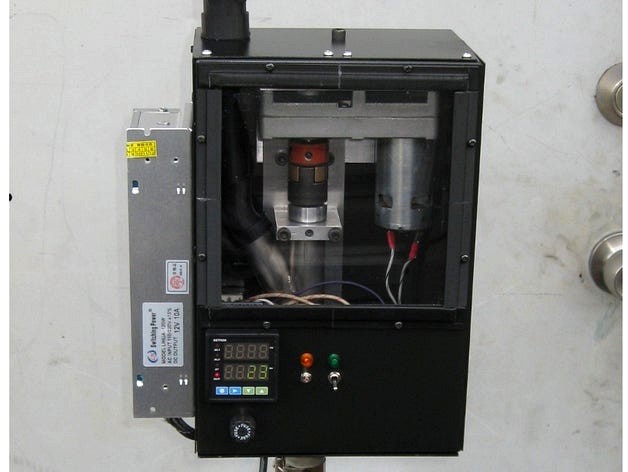
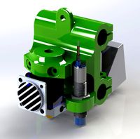
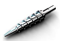
Auger barrel is 1" OD x .875" ID seamless 304 SS tubing and was single-point threaded on the bottom end. It, and the SS feed tube, were cupped with a 1" endmill @ 30 deg and welded together. The auger is a 7/8" "Jennings Pattern" screw bit, and its shank had to be trued and turned down on a lathe to 8mm to fit into an 8mm shaft collar and 8mm ball bearing. A thrust bearing stacked on top of the shat collar pushes against an aluminum plug that's been pinned to the auger barrel with a 5-40 screw. On the top end of the alu plug is a counter-bore to press fit the 8mm bearing into. On the bottom threaded portion of the barrel, an aluminum heat sink/hot-end with an internal 30 degree taper terminating to a 7/16-14 thread, screws on, and the brass extruder nozzle screws into the 7/16-14 thread. The heatsink is heated with a 1" 250w band heater. For the thermocouple, a 1/16" hole was drilled into the heatsink adjacent to the 7/16-14 thread and between where the band heater splits
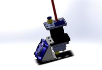
Motor is the "BetaMotor" featured on filastruder.com. It was fastened to 4" x 1/4" aluminum angle with one leg milled down to 3", and the angle fastened to a 1/4" x 2" aluminum bar. The betamotor came with a square drive shaft, so I replaced the shaft with a 1/2" rod turned down to 3/8" on the drive end to fit into a 3/8" Lovejoy equipped w/ bronze spider.
The power supply for the motor (externally mounted on the left side) was a ~$25 12vdc10A LED power supply off Amazon.
Housing dimensions: 6.5" width x 5" depth x 10" height.
I used a rotabroach to cut the 1" and 1.25" holes in what were to be the top and bottom before I bent it on a magnabend. All other holes, the PID, and window cut-outs were drilled or nipped after bending. After bending, the auger/motor brace assembly w/ spacers added was put into place, and the spacers were then traced around with a pencil to map where the housing mount holes should be. Six 1" pieces of 1/2"x1/8" angle were riveted to the rear housing to serve as attachment points for the front half of the housing.
Auger barrel is 1" OD x .875" ID seamless 304 SS tubing and was single-point threaded on the bottom end. It, and the SS feed tube, were cupped with a 1" endmill @ 30 deg and welded together. The auger is a 7/8" "Jennings Pattern" screw bit, and its shank had to be trued and turned down on a lathe to 8mm to fit into an 8mm shaft collar and 8mm ball bearing. A thrust bearing stacked on top of the shat collar pushes against an aluminum plug that's been pinned to the auger barrel with a 5-40 screw. On the top end of the alu plug is a counter-bore to press fit the 8mm bearing into. On the bottom threaded portion of the barrel, an aluminum heat sink/hot-end with an internal 30 degree taper terminating to a 7/16-14 thread, screws on, and the brass extruder nozzle screws into the 7/16-14 thread. The heatsink is heated with a 1" 250w band heater. For the thermocouple, a 1/16" hole was drilled into the heatsink adjacent to the 7/16-14 thread and between where the band heater splits
Motor is the "BetaMotor" featured on filastruder.com. It was fastened to 4" x 1/4" aluminum angle with one leg milled down to 3", and the angle fastened to a 1/4" x 2" aluminum bar. The betamotor came with a square drive shaft, so I replaced the shaft with a 1/2" rod turned down to 3/8" on the drive end to fit into a 3/8" Lovejoy equipped w/ bronze spider.
The power supply for the motor (externally mounted on the left side) was a ~$25 12vdc10A LED power supply off Amazon.
Housing dimensions: 6.5" width x 5" depth x 10" height.
I used a rotabroach to cut the 1" and 1.25" holes in what were to be the top and bottom before I bent it on a magnabend. All other holes, the PID, and window cut-outs were drilled or nipped after bending. After bending, the auger/motor brace assembly w/ spacers added was put into place, and the spacers were then traced around with a pencil to map where the housing mount holes should be. Six 1" pieces of 1/2"x1/8" angle were riveted to the rear housing to serve as attachment points for the front half of the housing.
Similar models
thingiverse
free

8mm bar end mirror adapter by wingnut1000
... 2mm in abs.
update: replace model for bottom piece. original had error that made it too thick causing stock bolt to be short.
thingiverse
free

Heatbed Threaded Rod Support "Z" Axis by iMakebyDesign
...bearing, 10mm rod use a 6900zz bearing ( or similar ). locate the collars 19 - 20mm from end...
grabcad
free

Flanged Bearing for 1.5" Shaft
...uot; bolts. 5-1/8" square cast iron housing with 5/16-24 set screws to secure onto shaft. zerk grease fitting with dust cap.
thingiverse
free
5mm to 8mm Z axis shaft coupler by mrice
...ible shaft couplers on z axis rods, for 5mm motor shafts and 8mm threaded rods. use two m3x10mm screws and nuts to tighten down.
cults
free
Bearing block for 8mm (or 5/16") shafts/round rails
...rails
cults
bearing block for 8mm (or 5/16") shafts/round rails
bearing block for 8mm (or 5/16") shafts/round rails
thingiverse
free

Aluminum extrusion acoustic panel bracket by realmakermods
...t; thickness.
screws are m3 screws, 3.4mm clearance holes in the print. 5.8mm head diameter for the countersunk front screw file.
grabcad
free

Truncated Pants
...bolt circle straddling center
line.
16 - 7/16" x 3/4" slotted holes on 15 1/4" bolt circle straddling center line.
grabcad
free

3/8" Ball End Hex Screwdriver
...er
grabcad
3/8" hex drive with ball end that allows for 25 deg access angle, 11-1/4" oal, fits 7/16-14 and 1/2-13 shcs
grabcad
free

8mm Shaft Coupler
...looking for assembly solutions with shafts in an easy and versatile way.
https://www.robocore.net/mechanic-item/8mm-shaft-coupler
thingiverse
free

V-Belt Pulley for Motor - 1 inch diameter, 0.5 inch shaft by circa1023
...
this is a 1" pulley for a motor with a notched 1/2" diameter drive shaft. the set screw is a 1/16" untapped hole.
Unotre
thingiverse
free

SLA Metallic Microlattice test by unotre
...sla metallic microlattice test by unotre
thingiverse
microtruss1 = imperial units
microtruss2 = metric units
thingiverse
free
Afinia UP! Extruder Cable Box by unotre
...anyone wanting to modify the extruder cable box on afinia / up! printers but can't because of the proprietary .up3 file type.
thingiverse
free

Afinia UP! Indicator Mount / Holder by unotre
... temp switch).
your indicator should have a 3/4" or 1" probe attached in order to take readings close to the nozzle.
thingiverse
free

10mm Keck by Bruta1ity
...10mm keck by bruta1ity thingiverse scaled down unotre#39;s 14mm keck clip to fit my 10mm...
thingiverse
free
14/20 Keck Clip - ST/NS Glassware Taper Joint Clip by unotre
... splitting.
24/40 keck clip: http://www.thingiverse.com/thing:274563
19/22 keck clip: http://www.thingiverse.com/thing:275257
thingiverse
free

Torsen LSD - Limited Slip Differential by unotre
... the base plate should be printed lengthwise up so it has the lowest amount of contact area with the platform to prevent curling.
thingiverse
free

Torsen LSD SCALED by pachek
...this a remix of the torsen lsd designed by "unotrequot;. main change is that it is scaled by half...
thingiverse
free

Schmidt Coupling - Offset Coupling by unotre
...ed from the middle to prevent warping.
http://www.youtube.com/watch?v=04gz8nc38fu
https://www.youtube.com/watch?v=g2du1s2ukhq
thingiverse
free
24/40 Keck Clip - ST/NS Glassware Taper Joint Clip by unotre
..., no raft.
--
14/20 keck clip: http://www.thingiverse.com/thing:274395
19/22 keck clip: http://www.thingiverse.com/thing:275257
Extruder
3ddd
$1
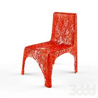
Extruded Chair
...extruded chair
3ddd
extruded , tom dixon
inspired by tom dixon extruded chair
turbosquid
$15
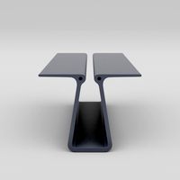
Extruded Table
... extruded table for download as blend, dae, fbx, obj, and stl on turbosquid: 3d models for games, architecture, videos. (1634137)
turbosquid
$2
3D Printer Extruder
...d
royalty free 3d model 3d printer extruder for download as on turbosquid: 3d models for games, architecture, videos. (1537359)
turbosquid
$1
Zombie extruded text
...oyalty free 3d model zombie extruded text for download as obj on turbosquid: 3d models for games, architecture, videos. (1322198)
turbosquid
$4
Extruder conical screw
...el extruder conical screw for download as sldpr, ige, and stl on turbosquid: 3d models for games, architecture, videos. (1524433)
turbosquid
$50
3d PRINTER - Extruder
... available on turbo squid, the world's leading provider of digital 3d models for visualization, films, television, and games.
turbosquid
$15
Extruded Table 2
...xtruded table 2 for download as blend, dae, fbx, obj, and stl on turbosquid: 3d models for games, architecture, videos. (1621846)
turbosquid
$10
Maya Extrude Tool
... available on turbo squid, the world's leading provider of digital 3d models for visualization, films, television, and games.
3d_export
$5

world earth extrude map
...world earth extrude map
3dexport
3ddd
$1
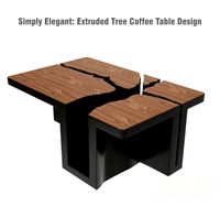
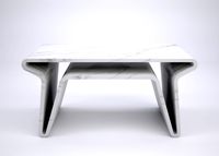
Simply Elegant Extruded Tree Coffee Table Design
...ble by link studios. the silhouette of a tree is visible at one angle, extruded from the surface to create the support structure.
Filament
3ddd
$1
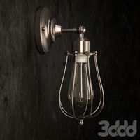
Filament Cage
...filament cage
3ddd
лофт , filament cage
модель бра, делалась по фото!
turbosquid
$3
FILAMENT COUNTER
...d
royalty free 3d model filament counter for download as stl on turbosquid: 3d models for games, architecture, videos. (1563049)
3d_export
$5

Filament lamp 3D Model
...filament lamp 3d model
3dexport
filament lamp 3d model kevin 54161 3dexport
3d_export
$5

Filament bulb candle 3D Model
...filament bulb candle 3d model
3dexport
filament bulb-candle
filament bulb candle 3d model kevin 54163 3dexport
3d_export
$5

Filament led light bulb
...filament led light bulb
3dexport
realistic 3d model of filament light bulb with v-ray materials.
3d_export
$5

Filament led light bulb
...filament led light bulb
3dexport
realistic 3d model of filament light bulb with v-ray materials.
3d_export
$5

Filament led light bulb
...filament led light bulb
3dexport
realistic 3d model of filament light bulb with v-ray materials.
3d_export
$5
Filament led light bulb
...filament led light bulb
3dexport
realistic 3d model of filament light bulb with v-ray materials.
3d_export
$5

Filament led light bulb
...filament led light bulb
3dexport
realistic 3d model of filament light bulb with v-ray materials.
3ddd
$1
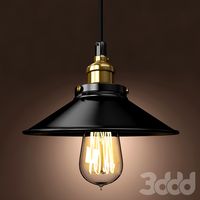
Factory filament metal shade
...factory filament metal shade
3ddd
restoration hardware
restoration hardware. 20th c. factory filament metal shade.