Thingiverse
Prusa "Slack Lack" Enclosure by GedKerezis
by Thingiverse
Last crawled date: 2 years, 10 months ago
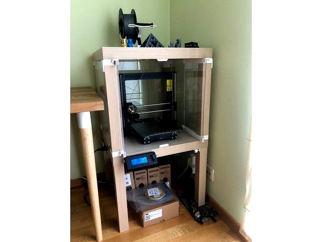
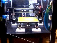
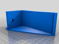
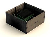
Dominik Cisar's Lack Enclosure is incredible and already contains so many great design considerations, but as a maker myself, I'm always looking to add something more. Knowing that I need to keep the enclosure doors open when printing with PLA, I wanted to find a design that could hide/slide/remove the doors so they wouldn't take up space in my room. I searched all over the internet until I found a perfect remix called the “Slack Lack”. The original designer nnorton00 incorporated these clever sliding-hinges that allow the doors to tuck back inside the enclosure keeping them neatly out of the way (video). He designed the “Slack Lack” to fit an Ender 3 with paving stone so the Plexiglass dimensions ended up being significantly taller than the ones called out in the original Lack enclosure. Unfortunately for me, I had already ordered Plexiglass for the original Lack enclosure, but decided I would remix nnorton00's design to fit! So if anyone else has the original Lack Plexiglass and wants to make an enclosure with fancy sliding doors, then this is the remix for you!
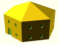
In the following instructions I use abbreviations to describe the location of the parts in the finished assembly. The abbreviations are defined as follows: TL → Top Left, TR → Top Right, BL → Bottom Left, BR → Bottom Right. I also made an exploded view drawing to help with assembly.
Build can also be found on PrusaPrinters
Purchase Parts:
QTY 12 - 20x6x2mm magnets (used to secure the doors from unwanted sliding and opening)
QTY 8 - 6x50mm wood screws (used to mount the corner pieces)
QTY 14 - 5x20mm wood screws (used to mount the table legs, catches, and door stop)
QTY 3 - 5x20mm wood screws (used to mount the PSU bracket)
QTY 1 - 3x10mm wood screw (used to secure the PSU in the bracket)
QTY 3 - 440x440mm thickness 3mm Plexiglass
QTY 2 - 220x440mm, thickness 3mm Plexiglass
Print Settings:
I used PrusaSlicer's recommended print settings for PETG at 0,2mm layer height
Added paint-on supports for corner_TL.stl & corner_TR.stl
Added brim and supports for the door rails (top_right_rail.stl & top_left_rail.stl & bottom_right_rail.stl & bottom_left_rail.stl)
Print 2x back_top_corner.stl 2x back_bottom_corner.stl 4x catch.stl
Assembly:
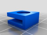
Press fit QTY 4 magnets into TL, TR, BL, BR corners (if they do not stay in use superglue)
Check magnet polarity in the corners then press fit QTY 4 magnets into the sliding hinges ensuring that the matching corner-hinge combination attracts
Use QTY 4 - 6x50mm screws to secure the top corners to the bottom-side of the upper table (use the pre-drilled holes in the lack table and the edges of the plastic part should align with the table)
Use QTY 8 - 5x20mm screws to secure the legs to the top corners (pre-dilled hole should face out)
Slide the QTY 3 big Plexiglass into the top corner pieces
Use QTY 4 - 6x50mm screws to secure the bottom corners to the legs (use the pre-drilled holes in the lack legs and the edges of the plastic part should align with the leg)
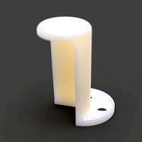
The locations of the 4x catch.stl vary at each corner so I created a “hole finder” part to help
Use a sticky note or some temporary sticker to identify the front side of the table (later we will install the door stop which will indicate the front)
Slide the hole finder over the front left corner until it aligns with the two perpendicular edges, then with a pen mark inside the circle labeled “FR L”
Slide the hole finder over the front right corner until it aligns with the two perpendicular edges, then with a pen mark inside the circle labeled “FR R”
Slide the hole finder over either of the back corners until it aligns with the two perpendicular edges, then with a pen mark inside the circle labeled “B”, repeat with the remaining corner
Use QTY 4 - 5x20mm screws to secure the catches to the top-side of the lower table
Place the upper table on top of the lower table making sure the side without the Plexiglass wall is aligned with the front indicating sticker on the lower table
Depending on if you want the door stop to be on the top or bottom, slide QTY 2 magnets into the TL & TR rail or the BL & BR rail
Use any PVA-based white glue (Elmer's school glue/crafting glue) and secure the TL rail and BL rail onto QTY 1 of the door Plexiglass, repeat for the right side
Immediately after securing the rails to the Plexiglass, slide the door subassembly through its respective corner pieces to ensure smooth movement
Let the door subassemblies dry for ~1 day
Put the sliding hinges into the hoops on their respective rails, the joints should feel tight so they don't flap around when sliding the doors in/out, use strips of paper to tighten if needed
Watch nnorton00's video to learn how to install and remove the doors
With the doors installed, check magnet polarity in the rails then slide QTY 2 magnets into the door stop ensuring that the doors are attracted to it
Close one of the doors and mark the location for the front face of the door stop then use QTY 2 - 5x20mm screws to secure the door stop onto the top-side of the lower table.
Finally, follow Prusa's Enclosure V2 guide for how to install the PSU externally
Below are links to the other parts that I used to complete my enclosure build:
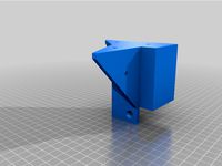
Angled heat bed cable cover
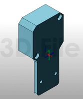
External PSU mount and replacement bracket (print file 11)
External LCD mount
Enclosure cable pass through (printed wider one to fit LCD cables)
Filament grommet
Spool holder
Steel sheet holder
If you have any questions please feel free to ask! I do not have time to add variations of the parts for different magnet/Plexiglass sizes so if you want to change them I can send a .zip file of my SolidWorks project.
In the following instructions I use abbreviations to describe the location of the parts in the finished assembly. The abbreviations are defined as follows: TL → Top Left, TR → Top Right, BL → Bottom Left, BR → Bottom Right. I also made an exploded view drawing to help with assembly.
Build can also be found on PrusaPrinters
Purchase Parts:
QTY 12 - 20x6x2mm magnets (used to secure the doors from unwanted sliding and opening)
QTY 8 - 6x50mm wood screws (used to mount the corner pieces)
QTY 14 - 5x20mm wood screws (used to mount the table legs, catches, and door stop)
QTY 3 - 5x20mm wood screws (used to mount the PSU bracket)
QTY 1 - 3x10mm wood screw (used to secure the PSU in the bracket)
QTY 3 - 440x440mm thickness 3mm Plexiglass
QTY 2 - 220x440mm, thickness 3mm Plexiglass
Print Settings:
I used PrusaSlicer's recommended print settings for PETG at 0,2mm layer height
Added paint-on supports for corner_TL.stl & corner_TR.stl
Added brim and supports for the door rails (top_right_rail.stl & top_left_rail.stl & bottom_right_rail.stl & bottom_left_rail.stl)
Print 2x back_top_corner.stl 2x back_bottom_corner.stl 4x catch.stl
Assembly:
Press fit QTY 4 magnets into TL, TR, BL, BR corners (if they do not stay in use superglue)
Check magnet polarity in the corners then press fit QTY 4 magnets into the sliding hinges ensuring that the matching corner-hinge combination attracts
Use QTY 4 - 6x50mm screws to secure the top corners to the bottom-side of the upper table (use the pre-drilled holes in the lack table and the edges of the plastic part should align with the table)
Use QTY 8 - 5x20mm screws to secure the legs to the top corners (pre-dilled hole should face out)
Slide the QTY 3 big Plexiglass into the top corner pieces
Use QTY 4 - 6x50mm screws to secure the bottom corners to the legs (use the pre-drilled holes in the lack legs and the edges of the plastic part should align with the leg)
The locations of the 4x catch.stl vary at each corner so I created a “hole finder” part to help
Use a sticky note or some temporary sticker to identify the front side of the table (later we will install the door stop which will indicate the front)
Slide the hole finder over the front left corner until it aligns with the two perpendicular edges, then with a pen mark inside the circle labeled “FR L”
Slide the hole finder over the front right corner until it aligns with the two perpendicular edges, then with a pen mark inside the circle labeled “FR R”
Slide the hole finder over either of the back corners until it aligns with the two perpendicular edges, then with a pen mark inside the circle labeled “B”, repeat with the remaining corner
Use QTY 4 - 5x20mm screws to secure the catches to the top-side of the lower table
Place the upper table on top of the lower table making sure the side without the Plexiglass wall is aligned with the front indicating sticker on the lower table
Depending on if you want the door stop to be on the top or bottom, slide QTY 2 magnets into the TL & TR rail or the BL & BR rail
Use any PVA-based white glue (Elmer's school glue/crafting glue) and secure the TL rail and BL rail onto QTY 1 of the door Plexiglass, repeat for the right side
Immediately after securing the rails to the Plexiglass, slide the door subassembly through its respective corner pieces to ensure smooth movement
Let the door subassemblies dry for ~1 day
Put the sliding hinges into the hoops on their respective rails, the joints should feel tight so they don't flap around when sliding the doors in/out, use strips of paper to tighten if needed
Watch nnorton00's video to learn how to install and remove the doors
With the doors installed, check magnet polarity in the rails then slide QTY 2 magnets into the door stop ensuring that the doors are attracted to it
Close one of the doors and mark the location for the front face of the door stop then use QTY 2 - 5x20mm screws to secure the door stop onto the top-side of the lower table.
Finally, follow Prusa's Enclosure V2 guide for how to install the PSU externally
Below are links to the other parts that I used to complete my enclosure build:
Angled heat bed cable cover
External PSU mount and replacement bracket (print file 11)
External LCD mount
Enclosure cable pass through (printed wider one to fit LCD cables)
Filament grommet
Spool holder
Steel sheet holder
If you have any questions please feel free to ask! I do not have time to add variations of the parts for different magnet/Plexiglass sizes so if you want to change them I can send a .zip file of my SolidWorks project.
Similar models
thingiverse
free

Lack enclosure for Wanhao i3Plus by TorgeirN
...and some hinges for the door. it is very similar to other enclosure designs here on thingiverse, but made...
thingiverse
free

Printer Enclosure Door Magnet Mount by esmsnt
...f the inner walls in the corner of the poly-carbonate and slipped the magnet in between, friction fit is plenty to keep it there.
thingiverse
free
IKEA LACK Ender 3 Enclosure by Olivarius
...ddle to attach it to the lack table, this adds rigidity.
i hope you guys like it, if you do make one please let me know.
thanks.
thingiverse
free

Prusa Lack Enclosure by johnsmith387
...some company, and the original designer of these parts.
each unit is attached with a 6×20 mm screw (or 3/4" #14 wood screw).
thingiverse
free

Flsun Kossel Plexiglass Enclosure by Xlemos
...el is hold with 6 10mm x 3mm magnets.
print: 3x corner back, 4x corner front, 1x corner front bottom r, 1x corner front bottom l.
thingiverse
free

Plexiglass Trim With Magnets For Lack Enclosure by dreidrei
...other gluing the trim together or to the plexiglass. unfortunately the top right corner was slightly exposed.
step file included.
thingiverse
free
Lack Table Enclosure Parts by Kasudamt
...ve/replace a wall. i added hinges for the door but they are sort of a half hinge so that the door is still removable if desired.
thingiverse
free
Plexiglass Magnet Adapter by SimplicityGuy
...enclosure (https://www.thingiverse.com/thing:1843235), since i cut the plexiglass to be too big and didn't want to re-cut it.
thingiverse
free

Lack enclosure side mounting PSU brackets V1 by bobthebuilder606
...rew in first and adjust the height as needed. once you have the height set tighten the top screw down then add the bottom screws.
thingiverse
free
Prusa Lack Enclosure Modified PSU Holder by cjsharp1
...hole to the side of the holder, and it provides a little more room for the wires to fit between the psu and the leg of the table.

Slack
turbosquid
$8

slack line hitch knot
...ine hitch knot for download as fbx, stl, 3ds, x, dae, and obj on turbosquid: 3d models for games, architecture, videos. (1667340)
archive3d
free

Rack 3D Model
...3d model archive3d rack for clothing rack pants rack slack n290114 - 3d model (*.gsm+*.3ds) for interior 3d...
3d_export
$35

Man1 3D Model
...people rigged t-pose detailed realistic standing casual clothing pants slack trousers jacket leather shirt guy young human character man1...
evermotion
$8

trousers 21 am102
...am102 evermotion key 21 trousers clothes textile am102 pants slack highly detailed model of trousers with all textures, shaders...
evermotion
$10

clothes 29 am102
...key 29 trousers clothes textile am102 jacket suit pants slack highly detailed models of clothes with all textures, shaders...
evermotion
$10
clothes 26 am102
...26 shirt trousers clothes textile am102 sweater pants blouse slack highly detailed model of clothes with all textures, shaders...
3d_ocean
$5
Zombie Pants
...chinos clothes dead denims game gasps jeans khakis pants slack walking walking dead wash wheezes zombie realistic zombie pants...
evermotion
$120
Archmodels vol. 102
...rug carpet textile skirt sweater jacket suit pants blouse slack coat cap beanie sandals sweatshirt archmodels vol. 102 includes...
3d_export
$5

hanging pants folded hanging pants jeans pants trousers denim fashion clothing garment modern fold t
...cotton pocket jean texture style pant casual black pants slack cotton hanging clothing woman men"s display clothes wall retail...
3d_export
$5

hanging pants folded hanging pants jeans pants trousers denim fashion clothing garment modern fold t
...cotton pocket jean texture style pant casual black pants slack cotton hanging clothing woman men"s display clothes wall retail...
Lack
3d_export
$5

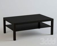
LACK LACK Coffee table white 90x55 cm IKEA
..., white, 90x55 cm ikea<br>https://www.ikea.com/ru/ru/p/lack-lakk-zhurnalnyy-stol-belyy-50449907/?ysclid=l8zshj49w6656165430
turbosquid
$4

Ikea Lack
... available on turbo squid, the world's leading provider of digital 3d models for visualization, films, television, and games.
3ddd
$1
IKEA Lack Coffee Table
... кофейный
ikea lack coffee tablehttp://www.ikea.com/gb/en/catalog/products/00104291
turbosquid
$5

IKEA Lack Table
...ack table for download as blend, blend, unitypackage, and fbx on turbosquid: 3d models for games, architecture, videos. (1623135)
turbosquid
$10

Ikea Lack Set
... available on turbo squid, the world's leading provider of digital 3d models for visualization, films, television, and games.
turbosquid
$3

IKEA Lack Library
... available on turbo squid, the world's leading provider of digital 3d models for visualization, films, television, and games.
turbosquid
$1

IKEA LACK TABLE
... available on turbo squid, the world's leading provider of digital 3d models for visualization, films, television, and games.
turbosquid
free

IKEA Lack Shelf
... available on turbo squid, the world's leading provider of digital 3d models for visualization, films, television, and games.
turbosquid
$9

Ikea Table 5 Lack
... available on turbo squid, the world's leading provider of digital 3d models for visualization, films, television, and games.
turbosquid
$5

IKEA Lack Side Table
... available on turbo squid, the world's leading provider of digital 3d models for visualization, films, television, and games.
Enclosure
3d_export
free
electrical enclosure
...l enclosure where electrical devices like (relays, contactors, busbars ) are kept in order to protect from hazardous environment.
turbosquid
$100

GPU Enclosure
...yalty free 3d model gpu enclosure for download as obj and stl on turbosquid: 3d models for games, architecture, videos. (1381061)
3d_export
$5
Electrical Enclosure
...ed. also has tower lights attaced on the top.<br>file format that are available:<br>.step<br>.obj<br>.stl
archive3d
free
Enclosure 3D Model
...closure 3d model
archive3d
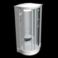
shower enclosure-acquarius- 3d model for interior 3d visualization.
archive3d
free
Enclosure 3D Model
...enclosure 3d model
archive3d
shower enclosure-omega- 3d model for interior 3d visualization.
archive3d
free
Enclosure 3D Model
...enclosure 3d model
archive3d
shower enclosure-vega - 3d model for interior 3d visualization.
archive3d
free
Enclosure 3D Model
...enclosure 3d model
archive3d
shower enclosure-zenith - 3d model for interior 3d visualization.
turbosquid
$20
shower enclosure
... available on turbo squid, the world's leading provider of digital 3d models for visualization, films, television, and games.
turbosquid
$14
Dumpster Enclosure
... available on turbo squid, the world's leading provider of digital 3d models for visualization, films, television, and games.
turbosquid
$25
3d printer enclosure
... model 3d printer enclosure for download as ipt, skp, and fbx on turbosquid: 3d models for games, architecture, videos. (1634310)
Prusa
turbosquid
$2
Frame Filament Guide Clip-On for Prusa Mk3
...rame filament guide clip-on for prusa mk3 for download as stl on turbosquid: 3d models for games, architecture, videos. (1634730)
3d_export
free
prusa i3 mk3s laser mount for opt lasers
...to learn more about the blue laser technology that conceived the cutting and engraving laser heads from opt lasers, please visit:
turbosquid
free
Prusa small printer adapter holder
...er for download as ipt, skp, dwg, dxf, fbx, ige, obj, and stl on turbosquid: 3d models for games, architecture, videos. (1642936)
3d_export
$30

geisha by jonathan adler
...** i did a 3d printing test in the prusa software, you can find it among the attached images.<br>exchange:<br>.blend...
thingiverse
free

Prusa without Prusa (rc2) by madless
...prusa without prusa (rc2) by madless
thingiverse
just the main part of prusa rc2 faceshield, without writing.
enjoy :)
thingiverse
free
Prusa by acejbc
...prusa by acejbc
thingiverse
prusa knob info
m3 8mm screw
thingiverse
free
Prusa house
...prusa house
thingiverse
how prusa house could look like...
thingiverse
free

Prusa Mk2 "Fake Prusa" LCD cover by anraf1001
...r by anraf1001
thingiverse
version of prusa's lcd cover with "fake prusa" instead of "original prusa"
thingiverse
free
Prusa stabilizator by gutiueugen
...prusa stabilizator by gutiueugen
thingiverse
prusa stabilizator
thingiverse
free
Keychain Prusa by rbarbalho
...keychain prusa by rbarbalho
thingiverse
keychain with text prusa.