Thingiverse
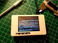
Prusa MK3S 3.5" PiTFT Mode by aharbick
by Thingiverse
Last crawled date: 3 years, 1 month ago
I started with this excellent design https://www.thingiverse.com/thing:3372513 and learned a few things and designed a couple of additional parts that were helpful.
Additional needed hardware:
Pi 4B (2GB is enough): https://www.adafruit.com/product/4292
PiTFT Plus 3.5": https://www.adafruit.com/product/2441
Pi Camera V2: https://www.adafruit.com/product/3099
Longer camera cable: https://www.adafruit.com/product/2143
MicroSD card: https://www.adafruit.com/product/2693
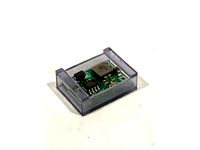
Buck converter: https://www.amazon.com/gp/product/B07N3QT628
Red/black cable: https://www.amazon.com/gp/product/B07D74RGVM
Eye connectors: https://www.amazon.com/gp/product/B01E4RAVI0
90-degree USB C cable: https://www.amazon.com/gp/product/B07VJNQT6F
Helpful documentation/examples I found:
Follow Octoprint installation: https://octoprint.org/download/
PiTFT instructions: https://learn.adafruit.com/adafruit-pitft-3-dot-5-touch-screen-for-raspberry-pi/easy-install-2
Not a Prusa but a nice example of wiring up a buck converter https://www.youtube.com/watch?v=OK7URi5LZhQ
Lessons / Assembly details:
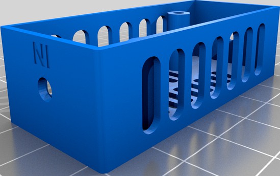
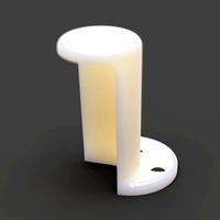
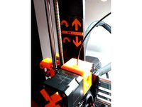
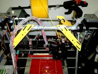
From the original design... the "clearance of 25mm" is CRUCIAL otherwise the screen mounts don't fit and the printer bed runs into the screen... I overlooked that multiple times. That is why I've included the "tpu_foot". They just pop into the frame.
In order for the PiTFT to fit into the case you have to snap the tables with circular mounts off of the unit. I used some needle-nose pliers and just bent them towards the back of the board and they snapped off easily.
When connecting to the EINSY board on the Prusa only the left 4 terminals come from the PSA. I originally connected to the heat-bed terminals and obviously got no power. Use a volt meter to find which terminals have power and be sure to connect to the correct red/black cables.
When cutting up your USB-C cable you may not have a black cable. Apparently this is a cost saving technique. There are typically some bare wires inside of the shield that are the black/negative wires.
Printing/assembly details:
Use TPU to print the "tpu" parts. I used 92A SainSmart (it's really nice and squishy): https://www.amazon.com/gp/product/B08L3NDG3H
Other parts I printed with PLA 0.2mm.
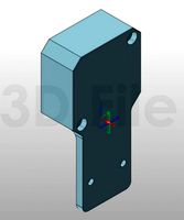
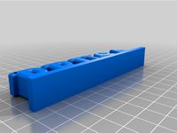
The buck converter above doesn't fit in the original case (yours might) which is why I've included the "tpu_buck_converter_holder". I didn't put holes in it because I wasn't sure how it would work with TPU/infill... I printed with 50% infill on this part and then just drilled holes. Because it's TPU they "close up" so you need a bigger bit than you think. Once you've drilled the holes push the buck converter holder into the frame on the bottom. Then use a M3x5mm hex-head screw and just work it through the buck converter corner holes and into the holes you drilled.
These wire strippers were awesome for stripping the wire, crimping the eye connector on, etc. https://www.amazon.com/gp/product/B000OQ21CA
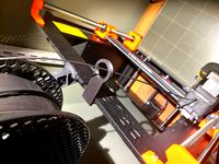
I used this camera mount: https://www.thingiverse.com/thing:4514535
Additional needed hardware:
Pi 4B (2GB is enough): https://www.adafruit.com/product/4292
PiTFT Plus 3.5": https://www.adafruit.com/product/2441
Pi Camera V2: https://www.adafruit.com/product/3099
Longer camera cable: https://www.adafruit.com/product/2143
MicroSD card: https://www.adafruit.com/product/2693
Buck converter: https://www.amazon.com/gp/product/B07N3QT628
Red/black cable: https://www.amazon.com/gp/product/B07D74RGVM
Eye connectors: https://www.amazon.com/gp/product/B01E4RAVI0
90-degree USB C cable: https://www.amazon.com/gp/product/B07VJNQT6F
Helpful documentation/examples I found:
Follow Octoprint installation: https://octoprint.org/download/
PiTFT instructions: https://learn.adafruit.com/adafruit-pitft-3-dot-5-touch-screen-for-raspberry-pi/easy-install-2
Not a Prusa but a nice example of wiring up a buck converter https://www.youtube.com/watch?v=OK7URi5LZhQ
Lessons / Assembly details:
From the original design... the "clearance of 25mm" is CRUCIAL otherwise the screen mounts don't fit and the printer bed runs into the screen... I overlooked that multiple times. That is why I've included the "tpu_foot". They just pop into the frame.
In order for the PiTFT to fit into the case you have to snap the tables with circular mounts off of the unit. I used some needle-nose pliers and just bent them towards the back of the board and they snapped off easily.
When connecting to the EINSY board on the Prusa only the left 4 terminals come from the PSA. I originally connected to the heat-bed terminals and obviously got no power. Use a volt meter to find which terminals have power and be sure to connect to the correct red/black cables.
When cutting up your USB-C cable you may not have a black cable. Apparently this is a cost saving technique. There are typically some bare wires inside of the shield that are the black/negative wires.
Printing/assembly details:
Use TPU to print the "tpu" parts. I used 92A SainSmart (it's really nice and squishy): https://www.amazon.com/gp/product/B08L3NDG3H
Other parts I printed with PLA 0.2mm.
The buck converter above doesn't fit in the original case (yours might) which is why I've included the "tpu_buck_converter_holder". I didn't put holes in it because I wasn't sure how it would work with TPU/infill... I printed with 50% infill on this part and then just drilled holes. Because it's TPU they "close up" so you need a bigger bit than you think. Once you've drilled the holes push the buck converter holder into the frame on the bottom. Then use a M3x5mm hex-head screw and just work it through the buck converter corner holes and into the holes you drilled.
These wire strippers were awesome for stripping the wire, crimping the eye connector on, etc. https://www.amazon.com/gp/product/B000OQ21CA
I used this camera mount: https://www.thingiverse.com/thing:4514535
Similar models
thingiverse
free

PiTFT Support for Raspberry Pi model B by sergeychernyshev
...del b:https://www.adafruit.com/products/1601
to be used with pitft enclosure by adafruit:https://www.adafruit.com/products/1892
grabcad
free

PiTFT PLUS 3.5" Touch Screen for Raspberry Pi by Adafruit
...raspberry pi by adafruit
grabcad
a perfectly-sized little display that plugs into your pi
https://www.adafruit.com/product/2441
thingiverse
free

Pi TFT Console for Old Adafruit 3.5" TFT by sausage_toes
...://www.adafruit.com/products/2441
and this is the adafruit 3.5" pitft version we have:https://www.adafruit.com/products/2097
thingiverse
free

CR-10 Integrated Octopi by goofdad
...video:http://youtu.be/oqyntqlazmu
i used #4 machine screws as i could not get 2.5mm screws long enough to go through the spacers.
thingiverse
free

Raspberry PI Charging Station (running repetier)
...ing ports:
https://www.amazon.com/gp/product/b07srzy9xh
the screen is shown running repetier, which i use to control my printers.
thingiverse
free

Adafruit PiTFT Plus 320x240 2.8" Bezel by gogodoit
...rotecting the top of your pitft.
it fits tight enough that it doesn't move around, and also secures the screen into position.
thingiverse
free

Ender 3 Touch Screen Enclosure
... to re-locate the touch screen
https://www.amazon.com/gp/product/b07gd2sw11/ref=ppx_yo_dt_b_asin_title_o04_s00?ie=utf8&psc=1
thingiverse
free
Eboot Buck Converter Holder by EXERGYOUTDOORS
...ppx_yo_dt_b_asin_title_o08_s00?ie=utf8&psc=1
i printed on a photon s using siraya tech "fast" resin in smoky black.
thingiverse
free
Raspberry Pi Retrogaming Case by Eguin
...for use in future projects, and if you have similar things already can be used in their place. in...
thingiverse
free
Case for Pi 2/B+ w/ Adafruit PiTFT by CrazyMonkeyBen
...uit.com/products/1601
the case includes access for all cables and ports, including routing the camera cable out any of 3 sides.
Aharbick
thingiverse
free

Prusa MK3 Tool Holder by aharbick
...is could collide with the original print and get jammed.
i chose to have one larger and deeper container space to hold all tools.
thingiverse
free

OpenScan Pi-edition Diffusor/Polarizer by aharbick
...or to compare it to the modified one. the 8th (last photo) image is an example of the incorrect way to put on the exterior film.
Pitft
thingiverse
free

PiTFT remix by MakersBox
...pitft remix by makersbox
thingiverse
added an opening for two of the gpio buttons.
thingiverse
free
PiTFT Support for Raspberry Pi model B by sergeychernyshev
...del b:https://www.adafruit.com/products/1601
to be used with pitft enclosure by adafruit:https://www.adafruit.com/products/1892
thingiverse
free

PiTFT/camera by cwaa
...mera by cwaa
thingiverse
i am experimenting with a pi 3 b and a 2.8 capacitive screen hooked to the pi camera in one enclosure.
thingiverse
free

Raspberry Pi Multilayer Case with PiTFT screen by tnever
... screwed together with #6 screws for a more solid feel and doesn't require a separate stand for a nice desktop viewing angle.
thingiverse
free

Adafruit PiTFT 2.8 for Raspberry by manelto
...adafruit pitft 2.8 for raspberry by manelto
thingiverse
adafruit pi tft definido para crear cajas a medida
thingiverse
free

PiTFT 2.2" displaytop by Ludwig100
... displaytop by ludwig100
thingiverse
this displaytop fits to raspberry pi 2 (or b+) case with 75mm/100mm vesa mount by 0110-m-p.
thingiverse
free

MP Mini 3.5 PiTFT Enclosure by BootsInShoes
...ct mini 3d printer. it uses the two front screws to hold it on. this is designed to have clearance for the mk8 aluminum extruder.
thingiverse
free

OctoPrint Raspberry Pi Rig 3.5" PiTFT Touch Display - Fits Pi 2/3 and PiTFT 2097 by abiv
... been added to the bottom case as well. lastly the opening for the power adapter has been enlarged to fit a wider array of plugs.
thingiverse
free

Adafruit PiTFT 2.8" board raiser by JayMc
...adafruit pitft 2.8" board raiser by jaymc
thingiverse
keeps the board flat while mounted on the pi
thingiverse
free
Raspberry Pi 3 case for PiTFT 2.8 with buttons by mikelduke
...s to the bottom.
adafruit pitft used in photos https://www.adafruit.com/product/1601
printed on a monoprice maker select mini v2
Mk3S
turbosquid
$50
cention mk3
...ty free 3d model cention mk3 for download as ma, obj, and fbx on turbosquid: 3d models for games, architecture, videos. (1454148)
turbosquid
$129
MK3 Tank
... available on turbo squid, the world's leading provider of digital 3d models for visualization, films, television, and games.
turbosquid
$100

Toyota Supra MK3
... available on turbo squid, the world's leading provider of digital 3d models for visualization, films, television, and games.
turbosquid
$44
cention mk3 low poly
...d model cention mk3 low poly for download as ma, obj, and fbx on turbosquid: 3d models for games, architecture, videos. (1454666)
turbosquid
$30
Challenger I Mk3 Falcon
... available on turbo squid, the world's leading provider of digital 3d models for visualization, films, television, and games.
turbosquid
$10

American Frag hand grenade MK3
...free 3d model american frag hand grenade mk3 for download as on turbosquid: 3d models for games, architecture, videos. (1393624)
turbosquid
$20
Mk3 US Navy Combat Knife
...ty free 3d model mk3 us navy combat knife for download as fbx on turbosquid: 3d models for games, architecture, videos. (1172791)
3d_export
$29

Ford Fiesta MK3 Modified 3D Model
...7 tumerfx mtumer mehmet t?mer 1993 1995 1996 wrc special modifed modifiye
ford fiesta mk3 modified 3d model mtumer 30698 3dexport
3d_export
$99

Toyota Supra Mk3 19861993 3D Model
...ort fast coupe japan 1986 1987 1988 1989 1990 1991 1992 1993 tuning turbo
toyota supra mk3 19861993 3d model squir 62530 3dexport
turbosquid
$5

Timothy Oulton Mars Chair MK3
...on mars chair mk3 for download as 3ds, max, obj, fbx, and dae on turbosquid: 3d models for games, architecture, videos. (1209782)
Mode
turbosquid
$29

Differential mode
...oyalty free 3d model differential 3d mode for download as iam on turbosquid: 3d models for games, architecture, videos. (1293829)
turbosquid
$45

Monk 3d mode
...rbosquid
royalty free 3d model monk 3d mode for download as on turbosquid: 3d models for games, architecture, videos. (1483647)
3d_ocean
$15

Naruto, Sage Mode
...ate with 3dsmax 2011. in max files, material/texture are standard material and mentalray material. preview rendered with 3dsma...
3ddd
free
Eichholtz La Mode
... лампа с тканевым абажуром, основа металлическая.http://www.eichholtz.com/lamp-table-la-mode-nickel-0085002626114.aspx
turbosquid
$45

Tyrannos mode 6_max
... available on turbo squid, the world's leading provider of digital 3d models for visualization, films, television, and games.
turbosquid
$15

Tyrannos mode 5_max
... available on turbo squid, the world's leading provider of digital 3d models for visualization, films, television, and games.
turbosquid
$15

Tyrannos mode 4_max
... available on turbo squid, the world's leading provider of digital 3d models for visualization, films, television, and games.
turbosquid
$15

Tyrannos mode 3_max
... available on turbo squid, the world's leading provider of digital 3d models for visualization, films, television, and games.
turbosquid
$15

Tyrannos mode 2_max
... available on turbo squid, the world's leading provider of digital 3d models for visualization, films, television, and games.
turbosquid
$15

Tyrannos mode 1_max
... available on turbo squid, the world's leading provider of digital 3d models for visualization, films, television, and games.
Prusa
turbosquid
$2
Frame Filament Guide Clip-On for Prusa Mk3
...rame filament guide clip-on for prusa mk3 for download as stl on turbosquid: 3d models for games, architecture, videos. (1634730)
3d_export
free
prusa i3 mk3s laser mount for opt lasers
...to learn more about the blue laser technology that conceived the cutting and engraving laser heads from opt lasers, please visit:
turbosquid
free
Prusa small printer adapter holder
...er for download as ipt, skp, dwg, dxf, fbx, ige, obj, and stl on turbosquid: 3d models for games, architecture, videos. (1642936)
3d_export
$30

geisha by jonathan adler
...** i did a 3d printing test in the prusa software, you can find it among the attached images.<br>exchange:<br>.blend...
thingiverse
free

Prusa without Prusa (rc2) by madless
...prusa without prusa (rc2) by madless
thingiverse
just the main part of prusa rc2 faceshield, without writing.
enjoy :)
thingiverse
free
Prusa by acejbc
...prusa by acejbc
thingiverse
prusa knob info
m3 8mm screw
thingiverse
free
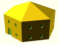
Prusa house
...prusa house
thingiverse
how prusa house could look like...
thingiverse
free

Prusa Mk2 "Fake Prusa" LCD cover by anraf1001
...r by anraf1001
thingiverse
version of prusa's lcd cover with "fake prusa" instead of "original prusa"
thingiverse
free
Prusa stabilizator by gutiueugen
...prusa stabilizator by gutiueugen
thingiverse
prusa stabilizator
thingiverse
free
Keychain Prusa by rbarbalho
...keychain prusa by rbarbalho
thingiverse
keychain with text prusa.
5
turbosquid
$6

Rock 5-5
...urbosquid
royalty free 3d model rock 5-5 for download as obj on turbosquid: 3d models for games, architecture, videos. (1639063)
3d_export
$5
hinge 5
...hinge 5
3dexport
hinge 5
turbosquid
$10
A-5
... available on turbo squid, the world's leading provider of digital 3d models for visualization, films, television, and games.
turbosquid
$2
A-5
... available on turbo squid, the world's leading provider of digital 3d models for visualization, films, television, and games.
turbosquid
$12

Calligraphic Digit 5 Number 5
...hic digit 5 number 5 for download as max, obj, fbx, and blend on turbosquid: 3d models for games, architecture, videos. (1389333)
3ddd
$1

5 роз
...5 роз
3ddd
5 роз в стеклянной вазе
design_connected
$11

iPhone 5
...iphone 5
designconnected
apple iphone 5 computer generated 3d model.
3ddd
$1
Lola 5
...lola 5
3ddd
miniforms
lola 5 miniforms 300*65*134
3ddd
$1
Nexus 5
...dd
nexus , phone , телефон
google nexus 5 phone
3d_ocean
$15
iPhone 5
...iphone 5
3docean
3d 4d apple cinema iphone model modeling phone screen texture
iphone 5 3d model and texture realistic iphone 5.
3
turbosquid
$10
Mountain Bike 3 -3 of 3
...model mountain bike 3 (#3 of 3) for download as fbx and blend on turbosquid: 3d models for games, architecture, videos. (1438752)
turbosquid
$6

Rock 3-3
...urbosquid
royalty free 3d model rock 3-3 for download as obj on turbosquid: 3d models for games, architecture, videos. (1628065)
turbosquid
$29
Books 150 pieces 3-3-3
...books 150 pieces 3-3-3 for download as max, obj, fbx, and stl on turbosquid: 3d models for games, architecture, videos. (1384033)
turbosquid
$3

Genesis 3 Clothing 3
... available on turbo squid, the world's leading provider of digital 3d models for visualization, films, television, and games.
3d_export
$5
hinge 3
...hinge 3
3dexport
hinge 3
3ddd
$1
Розетка 3
...розетка 3
3ddd
розетка
розетка 3
turbosquid
$50

is-3
... available on turbo squid, the world's leading provider of digital 3d models for visualization, films, television, and games.
turbosquid
$10
Mountain Bike 3 -2 of 3
...model mountain bike 3 (#2 of 3) for download as fbx and blend on turbosquid: 3d models for games, architecture, videos. (1438750)
turbosquid
$10
Mountain Bike 1 -3 of 3
...model mountain bike 1 (#3 of 3) for download as fbx and blend on turbosquid: 3d models for games, architecture, videos. (1438743)
3d_export
$5

3 CATS
...3 cats
3dexport
3 cats pen holder