Thingiverse
Prusa I3 MK3 - New filament sensor adapter in a separate housing by SIE-Maker
by Thingiverse
Last crawled date: 3 years, 1 month ago
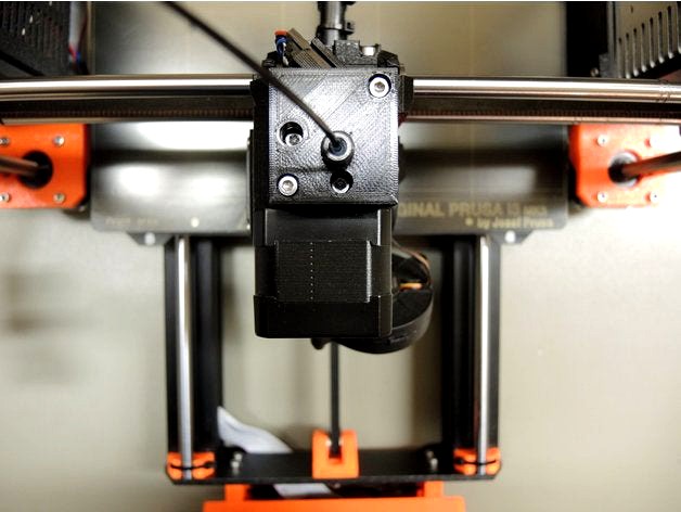
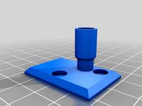
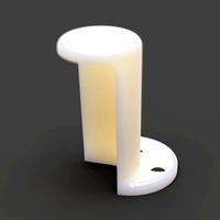
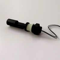
Prusa I3 MK3 - New filament sensor adapter in a separate housing.
Get rid of false-positiv alarms from the filament sensor!
09/06/19 News: There is a new variant for use with the Bondtech extruder https://www.thingiverse.com/thing:3681220
02/16/19 News: There is an upgrade for the MK3S-R4 extruder here:https://www.thingiverse.com/thing:3430687
10/02/18 Great News! V2 Upgrade with adjustable spring force!
With an additional M3x16mm screw on the left bottom side, it is now possible to fine tune the spring force for the ball bearing! This extension is especially useful for MMU owners.
Applies only to Part Top (A) and Part Bottom (B).
Recurring false alarms from the filament sensor of my Prusa I3 MK3 have urged me to look for a solution, Firmware 3.3.1, 3.4.0, now 3.4.1-RC1.
The cause of the false alarms are insufficient light reflections from the filament used.
Particularly shiny or transparent filaments provoke a too weak recognition with the optical motion sensor.
In order to avoid this circumstance, the filament movement is transmitted to the sensor via a small ball bearing in my solution.
The sensor thus sees only the movement of the ball bearing, the texture of the filament has become no matter.
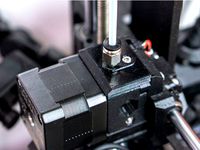
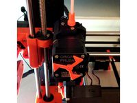
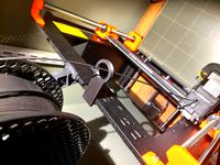
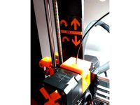
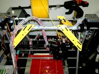
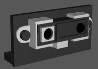
The adapter is exchanged with the existing filament cover on the extruder.
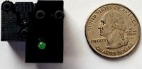
To remodel, the existing built-in MK3 filament sensor is removed and used in this new housing.
In addition, a ball bearing type MR63 (6x3x2.5mm, eg at Amazon), some PTFE tube and 2 screws M3x10mm are needed.
The previous connection cable of the sensor is used further and connected to the now 180 ° rotated sensor placed in the new housing.
The ball bearing is pushed onto the spring / axle fitting and inserted into the upper part of the housing.
With the flat side of the spring / axis facing to you, it snaps with some pressure in the top of the case.
The filament sensor is attached to the bottom part of the housing with the existing M3x10mm screw.
2 additional screws M3x10mm connect the two halves of the housing.
The upper part of the housing is available in 3 variants: With a thread to accommodate
some cm PTFE tubing and matching cover (regular 8.4mm outside dimension),
or with a Bowden (push-fit with 6mm thread or PRUSA style brass inlet) connection for eg an MMU extension.
The through hole for the PTFE tubing can be smoothed with a 4.0mm drill to make the tubing easier to place.
The PTFE tube should be lowered slightly at the ends, so that the filament slides in better.
It may be useful to roughen the surface on the outer radius of the ball bearing with, for example, sandpaper (600 ...) before installing it, depending on the type of bearing. This results in a better reflection for the sensor.
It is not necessary to make any changes to the firmware of the printer, I use currently V. 3.4.1-RC1 (German).
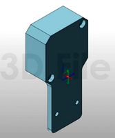
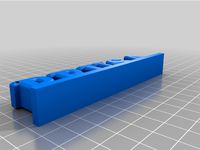
The adapter consists of the following components:
Housing top part in 3 variants,
Housing lower part,
Lid for the threaded inlet,
1 x spring / axle 32mm x 3mm.
1 x ball bearing MR63
a few cm of PTFE tube 4 / 2.5mm
5 x screw M3 x 10mm (3 x existing)
1 x screw M3 x 16mm, to adjust the spring force, don't use longer screws!
1 x Original Prusa Filament Sensor PCB (1 x existing)
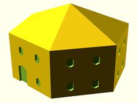
I print the components with PETG (http://www.dasfilament.de), 0.15mm layer height, 3 perimeter and 20% infill (Honeycomb).
Except for the upper part (eg fs-body_top_V2_A.stl), no supports are needed.
The top part has a few small overhangs and bridges, for me it worked without supports.
The printing should also work with PLA or ABS, but not testet yet.
Comments, questions and suggestions are always welcome.
I wish you happy printing
SIE-Maker
Get rid of false-positiv alarms from the filament sensor!
09/06/19 News: There is a new variant for use with the Bondtech extruder https://www.thingiverse.com/thing:3681220
02/16/19 News: There is an upgrade for the MK3S-R4 extruder here:https://www.thingiverse.com/thing:3430687
10/02/18 Great News! V2 Upgrade with adjustable spring force!
With an additional M3x16mm screw on the left bottom side, it is now possible to fine tune the spring force for the ball bearing! This extension is especially useful for MMU owners.
Applies only to Part Top (A) and Part Bottom (B).
Recurring false alarms from the filament sensor of my Prusa I3 MK3 have urged me to look for a solution, Firmware 3.3.1, 3.4.0, now 3.4.1-RC1.
The cause of the false alarms are insufficient light reflections from the filament used.
Particularly shiny or transparent filaments provoke a too weak recognition with the optical motion sensor.
In order to avoid this circumstance, the filament movement is transmitted to the sensor via a small ball bearing in my solution.
The sensor thus sees only the movement of the ball bearing, the texture of the filament has become no matter.
The adapter is exchanged with the existing filament cover on the extruder.
To remodel, the existing built-in MK3 filament sensor is removed and used in this new housing.
In addition, a ball bearing type MR63 (6x3x2.5mm, eg at Amazon), some PTFE tube and 2 screws M3x10mm are needed.
The previous connection cable of the sensor is used further and connected to the now 180 ° rotated sensor placed in the new housing.
The ball bearing is pushed onto the spring / axle fitting and inserted into the upper part of the housing.
With the flat side of the spring / axis facing to you, it snaps with some pressure in the top of the case.
The filament sensor is attached to the bottom part of the housing with the existing M3x10mm screw.
2 additional screws M3x10mm connect the two halves of the housing.
The upper part of the housing is available in 3 variants: With a thread to accommodate
some cm PTFE tubing and matching cover (regular 8.4mm outside dimension),
or with a Bowden (push-fit with 6mm thread or PRUSA style brass inlet) connection for eg an MMU extension.
The through hole for the PTFE tubing can be smoothed with a 4.0mm drill to make the tubing easier to place.
The PTFE tube should be lowered slightly at the ends, so that the filament slides in better.
It may be useful to roughen the surface on the outer radius of the ball bearing with, for example, sandpaper (600 ...) before installing it, depending on the type of bearing. This results in a better reflection for the sensor.
It is not necessary to make any changes to the firmware of the printer, I use currently V. 3.4.1-RC1 (German).
The adapter consists of the following components:
Housing top part in 3 variants,
Housing lower part,
Lid for the threaded inlet,
1 x spring / axle 32mm x 3mm.
1 x ball bearing MR63
a few cm of PTFE tube 4 / 2.5mm
5 x screw M3 x 10mm (3 x existing)
1 x screw M3 x 16mm, to adjust the spring force, don't use longer screws!
1 x Original Prusa Filament Sensor PCB (1 x existing)
I print the components with PETG (http://www.dasfilament.de), 0.15mm layer height, 3 perimeter and 20% infill (Honeycomb).
Except for the upper part (eg fs-body_top_V2_A.stl), no supports are needed.
The top part has a few small overhangs and bridges, for me it worked without supports.
The printing should also work with PLA or ABS, but not testet yet.
Comments, questions and suggestions are always welcome.
I wish you happy printing
SIE-Maker
Similar models
thingiverse
free
Prusa i3 MK3S Bowden Fitting Filament Sensor Cover by Yoonpyo
...k3s that you can screw in a pc4-m5/6/10 fitting. i use this to guide filament from the dry box to the extruder through ptfe tube.
thingiverse
free
Teflon Tube Prusa MK2.5/MK3 Filament Sensor Cover Upgrade by aitherios
...is is just a ptfe tube adaptor for the prusa mk2.5/mk3 filament sensor cover upgrade (https://www.thingiverse.com/thing:2748862)
thingiverse
free

prusa mk3 ptfe conversion by joorgawt
...prusa mk3 ptfe conversion by joorgawt
thingiverse
filament cover that takes a ptfe 1/4 x 28 quick connect for the prusa mk3
thingiverse
free
Hall Effect Filament Runout Sensor by Krpepe
...he tube around the bearings)
one for use with ptfe tube locks.
if you have any questions or suggestions please let me know.
kevin
thingiverse
free

MK3S Filament Sensor Cover Bowden Adapter (Tested with Mosaic Palette)
...tested with mosaic palette)
thingiverse
this is an edit of the prusa mk3s filament sensor cover to accept a palette bowden tube.
thingiverse
free

Filament sensor adapter with tacho speed encoder LM393 by lcortese
...g.
1 x magnet 6x10x2
build:
just print the piece, put the magnet before put the bearing, and insert the piece between the sensor.
thingiverse
free

MK3 Sensor Cover with threading by OliK
... a 2mm id 4mm od ptfe tube.
original stl from prusa github: https://github.com/prusa3d/original-prusa-i3/tree/mk3/printed-parts
thingiverse
free
PRUSA MK3 FILAMENT GUIDE FOR PALETTE+ by jaykav99
...ide to use the palette + with a prusa mk3, this part should replace your existing filament guide, yet still use the same screws.
thingiverse
free

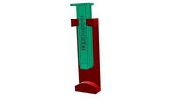
Prusa MK3S 44.3mm PTFE Tube Tool (X-Acto) by EngineerErrant
...gth for the prusa mk3s, using an x-acto #11 blade as the cutter. be sure to use a pair of pliers to insert the blade in the slot!
thingiverse
free

PolyBox PTFE adapter by adjuro
..., the adapter consists of a bottom part m8 screw with a hole inside connecting to the top part receiving the pneumatic connector.
Sie
turbosquid
$9

Chandra rugs SIE-32401
... available on turbo squid, the world's leading provider of digital 3d models for visualization, films, television, and games.
3d_export
$5

Flugzeuk
...bewertung meiner arbeiten ist mir wichtig, deswegen stelle ich sie kostenlos aus. -je suis un concepteur débutant et je...
3d_export
$5
Street
...bewertung meiner arbeiten ist mir wichtig, deswegen stelle ich sie kostenlos aus. -je suis un concepteur débutant et je...
3d_export
$5

Mimic
...bewertung meiner arbeiten ist mir wichtig, deswegen stelle ich sie kostenlos aus. -je suis un concepteur débutant et je...
3d_export
$5

The star wars fighter
...bewertung meiner arbeiten ist mir wichtig, deswegen stelle ich sie kostenlos aus. -je suis un concepteur débutant et je...
3d_export
$5

Sword in the cave
...bewertung meiner arbeiten ist mir wichtig, deswegen stelle ich sie kostenlos aus.<br>-je suis un concepteur débutant et je suis...
3dfindit
free

SIE
...sie
3dfind.it
catalog: festo
3dfindit
free

SIE
...sie
3dfind.it
catalog: festo
3dfindit
free
SIE
...sie
3dfind.it
catalog: festo
3dfindit
free

DGEA-..-SIE-M8
...dgea-..-sie-m8
3dfind.it
catalog: festo
Mk3
turbosquid
$50
cention mk3
...ty free 3d model cention mk3 for download as ma, obj, and fbx on turbosquid: 3d models for games, architecture, videos. (1454148)
turbosquid
$129
MK3 Tank
... available on turbo squid, the world's leading provider of digital 3d models for visualization, films, television, and games.
turbosquid
$100

Toyota Supra MK3
... available on turbo squid, the world's leading provider of digital 3d models for visualization, films, television, and games.
turbosquid
$44
cention mk3 low poly
...d model cention mk3 low poly for download as ma, obj, and fbx on turbosquid: 3d models for games, architecture, videos. (1454666)
turbosquid
$30

Challenger I Mk3 Falcon
... available on turbo squid, the world's leading provider of digital 3d models for visualization, films, television, and games.
turbosquid
$10
American Frag hand grenade MK3
...free 3d model american frag hand grenade mk3 for download as on turbosquid: 3d models for games, architecture, videos. (1393624)
turbosquid
$20
Mk3 US Navy Combat Knife
...ty free 3d model mk3 us navy combat knife for download as fbx on turbosquid: 3d models for games, architecture, videos. (1172791)
3d_export
$29

Ford Fiesta MK3 Modified 3D Model
...7 tumerfx mtumer mehmet t?mer 1993 1995 1996 wrc special modifed modifiye
ford fiesta mk3 modified 3d model mtumer 30698 3dexport
3d_export
$99

Toyota Supra Mk3 19861993 3D Model
...ort fast coupe japan 1986 1987 1988 1989 1990 1991 1992 1993 tuning turbo
toyota supra mk3 19861993 3d model squir 62530 3dexport
turbosquid
$5

Timothy Oulton Mars Chair MK3
...on mars chair mk3 for download as 3ds, max, obj, fbx, and dae on turbosquid: 3d models for games, architecture, videos. (1209782)
I3
3d_export
$10
suv i3
...suv i3
3dexport
suv i3 2013 series
3d_ocean
$89

BMW i3 2012
...y, in real units of measurement, qualitatively and maximally close to the original. model formats: - *.max (3ds max 2008 scanl...
cg_studio
$99

BMW i3 20143d model
...
cgstudio
.3ds .c4d .fbx .lwo .max .obj - bmw i3 2014 3d model, royalty free license available, instant download after purchase.
cg_studio
$99

BMW i3 20123d model
...tudio
.3ds .c4d .fbx .lwo .max .mb .obj - bmw i3 2012 3d model, royalty free license available, instant download after purchase.
cg_studio
$99

BMW i3 20143d model
...tudio
.3ds .c4d .fbx .lwo .max .mb .obj - bmw i3 2014 3d model, royalty free license available, instant download after purchase.
humster3d
$75

3D model of BMW i3 2014
...
buy a detailed 3d model of bmw i3 2014 in various file formats. all our 3d models were created maximally close to the original.
humster3d
$40

3D model of Kitchen Set I3
...uy a detailed 3d model of kitchen set i3 in various file formats. all our 3d models were created maximally close to the original.
3d_ocean
$30
Kitchen set i3
...ensils oven plates shelves sink table ware
kitchen set i3 include 3d models: cooker, oven, sink, cupboards, table, chair, plates.
3d_ocean
$89

BMW i3 2014
...y, in real units of measurement, qualitatively and maximally close to the original. model formats: - *.max (3ds max 2008 scanl...
cg_studio
$99

BMW i3 Concept 20113d model
...i3
.3ds .c4d .fbx .lwo .max .obj - bmw i3 concept 2011 3d model, royalty free license available, instant download after purchase.
Prusa
turbosquid
$2
Frame Filament Guide Clip-On for Prusa Mk3
...rame filament guide clip-on for prusa mk3 for download as stl on turbosquid: 3d models for games, architecture, videos. (1634730)
3d_export
free
prusa i3 mk3s laser mount for opt lasers
...to learn more about the blue laser technology that conceived the cutting and engraving laser heads from opt lasers, please visit:
turbosquid
free
Prusa small printer adapter holder
...er for download as ipt, skp, dwg, dxf, fbx, ige, obj, and stl on turbosquid: 3d models for games, architecture, videos. (1642936)
3d_export
$30

geisha by jonathan adler
...** i did a 3d printing test in the prusa software, you can find it among the attached images.<br>exchange:<br>.blend...
thingiverse
free

Prusa without Prusa (rc2) by madless
...prusa without prusa (rc2) by madless
thingiverse
just the main part of prusa rc2 faceshield, without writing.
enjoy :)
thingiverse
free
Prusa by acejbc
...prusa by acejbc
thingiverse
prusa knob info
m3 8mm screw
thingiverse
free
Prusa house
...prusa house
thingiverse
how prusa house could look like...
thingiverse
free

Prusa Mk2 "Fake Prusa" LCD cover by anraf1001
...r by anraf1001
thingiverse
version of prusa's lcd cover with "fake prusa" instead of "original prusa"
thingiverse
free
Prusa stabilizator by gutiueugen
...prusa stabilizator by gutiueugen
thingiverse
prusa stabilizator
thingiverse
free
Keychain Prusa by rbarbalho
...keychain prusa by rbarbalho
thingiverse
keychain with text prusa.
Sensor
3d_export
free

parking sensor
...parking sensor
3dexport
car parking sensor
turbosquid
$1
Sensor
... available on turbo squid, the world's leading provider of digital 3d models for visualization, films, television, and games.
3d_export
$5
Smoke sensor
...port
smoke sensor, can be an impressive element for your projects. easy to use, realistic image, low polygon, quality materials.
3d_export
$5
Air Quality Sensor v1
...air quality sensor v1
3dexport
air quality sensor v1
3d_export
$15
float sensor
...e up render. - all parts and materials are logically named. other formats ================= - collada (.dae) - autodesk fbx - obj
turbosquid
$26
Wind sensor C
...free 3d model wind sensor c for download as 3ds, obj, and fbx on turbosquid: 3d models for games, architecture, videos. (1328943)
turbosquid
$26
Wind sensor B
...free 3d model wind sensor b for download as 3ds, obj, and fbx on turbosquid: 3d models for games, architecture, videos. (1328168)
3d_export
$5
ultrasound sensor
...ivers convert ultrasound into electrical signals, and transceivers can both transmit and receive ultrasound. export in: -obj -fbx
3ddd
free
Вытяжка Shindo pallada sensor
... вытяжка
вытяжка shindo pallada sensor. в двух размерах - 600 и 900. текстуры в комплекте.
turbosquid
$52
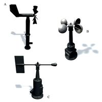
Wind sensor A B C
...
royalty free 3d model wind sensor a b c for download as fbx on turbosquid: 3d models for games, architecture, videos. (1408406)
Adapter
3d_export
$10
Adapter 3D Model
...adapter 3d model
3dexport
adapter
adapter 3d model mur 20260 3dexport
archive3d
free
Adapter socket 3D Model
...dapter socket adapter
adapter socket n090211 - 3d model (*.3ds) for interior 3d visualization.
turbosquid
$400

cell adaptation
...
royalty free 3d model cell adaptation for download as blend on turbosquid: 3d models for games, architecture, videos. (1701655)
archive3d
free
Adapter 3D Model
...ups pc equipment
adapter extron n180813 - 3d model (*.gsm+*.3ds) for interior 3d visualization.
turbosquid
$5

usb adapter
...royalty free 3d model usb adapter for download as ige and stl on turbosquid: 3d models for games, architecture, videos. (1582234)
turbosquid
$15
Power adapter
...free 3d model power adapter for download as max, obj, and fbx on turbosquid: 3d models for games, architecture, videos. (1510024)
turbosquid
$8
USB adapter
...e 3d model usb adapter for download as max, fbx, obj, and dwg on turbosquid: 3d models for games, architecture, videos. (1713542)
turbosquid
$30

adapter.3ds
... available on turbo squid, the world's leading provider of digital 3d models for visualization, films, television, and games.
turbosquid
$15

Nokia Adapter
... available on turbo squid, the world's leading provider of digital 3d models for visualization, films, television, and games.
turbosquid
$15
Universal adapter
... available on turbo squid, the world's leading provider of digital 3d models for visualization, films, television, and games.
Filament
3ddd
$1
Filament Cage
...filament cage
3ddd
лофт , filament cage
модель бра, делалась по фото!
turbosquid
$3
FILAMENT COUNTER
...d
royalty free 3d model filament counter for download as stl on turbosquid: 3d models for games, architecture, videos. (1563049)
3d_export
$5

Filament lamp 3D Model
...filament lamp 3d model
3dexport
filament lamp 3d model kevin 54161 3dexport
3d_export
$5

Filament bulb candle 3D Model
...filament bulb candle 3d model
3dexport
filament bulb-candle
filament bulb candle 3d model kevin 54163 3dexport
3d_export
$5

Filament led light bulb
...filament led light bulb
3dexport
realistic 3d model of filament light bulb with v-ray materials.
3d_export
$5

Filament led light bulb
...filament led light bulb
3dexport
realistic 3d model of filament light bulb with v-ray materials.
3d_export
$5

Filament led light bulb
...filament led light bulb
3dexport
realistic 3d model of filament light bulb with v-ray materials.
3d_export
$5
Filament led light bulb
...filament led light bulb
3dexport
realistic 3d model of filament light bulb with v-ray materials.
3d_export
$5

Filament led light bulb
...filament led light bulb
3dexport
realistic 3d model of filament light bulb with v-ray materials.
3ddd
$1
Factory filament metal shade
...factory filament metal shade
3ddd
restoration hardware
restoration hardware. 20th c. factory filament metal shade.
Separate
turbosquid
$20

Separator
...rbosquid
royalty free 3d model separator for download as max on turbosquid: 3d models for games, architecture, videos. (1309755)
3ddd
$1
separator
...separator
3ddd
showroom decorations :-)
turbosquid
$6
separator
...ree 3d model separator for download as max, obj, fbx, and 3ds on turbosquid: 3d models for games, architecture, videos. (1675368)
turbosquid
$19

Separator 01
...squid
royalty free 3d model separator 01 for download as max on turbosquid: 3d models for games, architecture, videos. (1334711)
turbosquid
$1
Separator 9
...y free 3d model separator 9 for download as max, obj, and fbx on turbosquid: 3d models for games, architecture, videos. (1455458)
turbosquid
$1
Separator 8
...y free 3d model separator 8 for download as max, obj, and fbx on turbosquid: 3d models for games, architecture, videos. (1455455)
turbosquid
$1

wooden separator
...e 3d model wooden separator for download as max, fbx, and obj on turbosquid: 3d models for games, architecture, videos. (1648793)
turbosquid
$1

Separator Colored
...odel separator colored for download as 3ds, max, obj, and fbx on turbosquid: 3d models for games, architecture, videos. (1408919)
turbosquid
$49
Separation Equipment
...on equipment for download as max, 3ds, dae, dwg, fbx, and obj on turbosquid: 3d models for games, architecture, videos. (1611535)
3d_export
$5

wooden separator
...can be an impressive element for your projects. realistic image, low polygon.<br>can make your work easier on your projects
New
turbosquid
$119

New New Beetle
... available on turbo squid, the world's leading provider of digital 3d models for visualization, films, television, and games.
3d_export
$5

New-feather
...new-feather
3dexport
new-feather
3d_export
$6

new style
...new style
3dexport
new style room
3ddd
free
New Items
...ew items
3ddd
new items , барный
барный стул от китайского производителя фирмы new items
3d_export
$6

Logo new
...logo new
3dexport
new american style logo
3d_export
$10

New jersey
...new jersey
3dexport
new jersey stp and stl format
design_connected
$20
New Deal
...new deal
designconnected
new deal computer generated 3d model.
3d_ocean
$15
New bed
... for this bed all this file format include in zip file 3ds,obj,max,zip file change material and re-size very easy very for render
3ddd
free

Sofa-New Classic
...sofa-new classic
3ddd
new classic
sofa,new classic
design_connected
$13
New Antiques
...new antiques
designconnected
cappellini new antiques computer generated 3d model. designed by wanders, marcel.
Maker
3d_ocean
$17
Coffee Maker
...coffee maker
3docean
breakfast coffee drip electric maker morning
detailed coffee maker and a plug.
3ddd
$1

coffee maker
...coffee maker
3ddd
кофемашина
coffee maker
3d_export
$10
chapati maker
...chapati maker
3dexport
it is a indian traditional chapati maker
archibase_planet
free
Coffee maker
...aker
archibase planet
percolator coffee-machine coffee maker
coffee maker - 3d model (*.gsm+*.3ds) for interior 3d visualization.
archibase_planet
free
Coffee maker
...aker
archibase planet
percolator coffee-machine coffee maker
coffee maker - 3d model (*.gsm+*.3ds) for interior 3d visualization.
archibase_planet
free

Coffee maker
...aker
archibase planet
percolator coffee-machine coffee maker
coffee maker - 3d model (*.gsm+*.3ds) for interior 3d visualization.
archibase_planet
free

Сoffee maker
...er
archibase planet
coffee maker percolator coffee-machine
сoffee maker n020112 - 3d model (*.3ds) for interior 3d visualization.
archibase_planet
free
Coffee maker
...aker
archibase planet
coffee maker percolator coffee-machine
coffee maker - 3d model (*.gsm+*.3ds) for interior 3d visualization.
3ddd
$1

Juice Maker
...juice maker
3ddd
соковыжималка
fully detailed kenwood juice maker
archibase_planet
free

Coffee maker
...hibase planet
coffee maker percolator coffee-machine
coffee maker n140611 - 3d model (*.gsm+*.3ds) for interior 3d visualization.
Housing
archibase_planet
free

House
...t
house residential house private house wooden house
house wooden n290815 - 3d model (*.gsm+*.3ds) for exterior 3d visualization.
archibase_planet
free

House
...use residential house private house wooden house
house wood stone n140815 - 3d model (*.gsm+*.3ds) for exterior 3d visualization.
archibase_planet
free

House
...ibase planet
house residential house building private house
house n050615 - 3d model (*.gsm+*.3ds) for exterior 3d visualization.
archibase_planet
free

House
...ibase planet
house residential house building private house
house n030615 - 3d model (*.gsm+*.3ds) for exterior 3d visualization.
archibase_planet
free

House
...ibase planet
house residential house building private house
house n230715 - 3d model (*.gsm+*.3ds) for exterior 3d visualization.
archibase_planet
free

House
...ibase planet
house residential house building private house
house n240615 - 3d model (*.gsm+*.3ds) for exterior 3d visualization.
archibase_planet
free

House
...ibase planet
house residential house building private house
house n290815 - 3d model (*.gsm+*.3ds) for exterior 3d visualization.
archibase_planet
free

House
...ibase planet
house residential house building private house
house n110915 - 3d model (*.gsm+*.3ds) for exterior 3d visualization.
archibase_planet
free

House
...ibase planet
house residential house building private house
house n120915 - 3d model (*.gsm+*.3ds) for exterior 3d visualization.
archibase_planet
free

House
...ibase planet
house residential house building private house
house n210915 - 3d model (*.gsm+*.3ds) for exterior 3d visualization.