GrabCAD

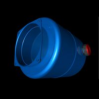
Project X Titan: Hydraulic Diagram PART #6
by GrabCAD
Last crawled date: 2 years ago
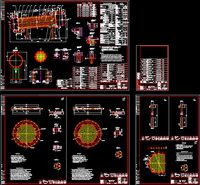
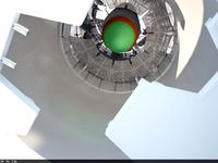
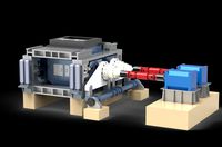
This is the Hydraulic Diagram of X Titan:
The first throttle valve in the Diagram regulates the flow of the hydraulic oil that goes to the hydraulic cylinders.
The flow dividing manifold is a hexagon that contains throttle valves, in order to synchronize the motion of the hydraulic cylinders.
Previous parts of Project X Titan:
https://grabcad.com/library/project-x-titan-5000kg-base-flange-with-stress-distributor-part-1-1
https://grabcad.com/library/project-x-titan-5000kg-base-flange-without-stress-distributor-part-2-1
https://grabcad.com/library/project-x-titan-5000kg-stress-distributor-part-3-1
https://grabcad.com/library/project-x-titan-5000kg-mounting-shaft-assembly-part-4-1
https://grabcad.com/library/project-x-titan-simulation-5000kg-mounting-shaft-assembly-on-base-flangepart-5-1
What is Project X Titan:
It is the fully calculated design of a 5000Kg Hydraulic Scrap Grip.
Purpose of Project X Titan:
I started to calculate and design a hydraulic grip for collection of scrap metal and I am going to upload it part by part and explain the calculations via simulation.
Please like and comment!!!
Similar models
grabcad
free

Project X Titan: How Hydraulics work PART #7
...ydraulic grip for collection of scrap metal and i am going to upload it part by part and explain the calculations via simulation.
grabcad
free

Project X Titan: 5000Kg Mounting Shaft Assembly PART #4
... of scrap metal and i am going to upload it part by part and explain the calculations via simulation.
please like and comment!!!
grabcad
free

Project X Titan: SIMULATION 5000Kg Mounting Shaft Assembly on Base FlangePART #5
... of scrap metal and i am going to upload it part by part and explain the calculations via simulation.
please like and comment!!!
grabcad
free

Project X Titan: 5000Kg Stress Distributor PART #3
... of scrap metal and i am going to upload it part by part and explain the calculations via simulation.
please like and comment!!!
grabcad
free

Project X Titan: 5000Kg Base Flange without Stress Distributor PART #2
...ment!!!
see here previous parts: https://grabcad.com/library/project-x-titan-5000kg-base-flange-with-stress-distributor-part-1-1
grabcad
free

Project X Titan: 5000Kg Base Flange with Stress Distributor PART #1
... of scrap metal and i am going to upload it part by part and explain the calculations via simulation.
please like and comment!!!
grabcad
free

M72 Project Katyusha- Exhaust Pipes
...assembly-1
https://grabcad.com/library/m72-motorcycle-drive-shaft-assembly-1
https://grabcad.com/library/m72-motorcycle-project-1
grabcad
free

M72 Project Katyusha- Headlamp Assembly
...://grabcad.com/library/m-72-collaboration-project-sidecar-military-version-1
https://grabcad.com/library/m72-motorcycle-project-1
grabcad
free

Double Effect Cylinder with hydraulic oil station
...inder-2)
oil pump station (thanks to mike https://grabcad.com/library/hydraulic-oil-station-2
4/3 valve
parker pipes and fittings
grabcad
free

CP Hydraulic Cylinder
...er
pallet jack:
http://grabcad.com/library/manual-pallet-stacker
scissor lift:
http://grabcad.com/library/scissor-lift--5/files
Diagram
design_connected
$18

Diagram Bench
...diagram bench
designconnected
nola industrier diagram bench computer generated 3d model. designed by lindencrona, clara.
turbosquid
$2

Curved Diagram Graph
... available on turbo squid, the world's leading provider of digital 3d models for visualization, films, television, and games.
3d_export
$12
33m3 tubular heat exchanger diagram
...33m3 tubular heat exchanger diagram
3dexport
33m3 tubular heat exchanger diagram
3d_export
$18

tang dynasty-tomb-eight diagrams-taoism
...tang dynasty-tomb-eight diagrams-taoism
3dexport
tang dynasty-tomb-eight diagrams-taoism<br>3ds max 2015
3d_export
$7
milling machine spindle drive diagram - milling gearbox
... n = 4500 rin / min; maximum power p = 7.5 kw. bt40 spindle, like welcome to download to learn. there are igs format files in it.
3d_export
$22
50 ton bridge crane mechanical and electrical diagram
...andled according to special requirements. 3. the running track of the crane shall comply with the provisions of gb10183 standard.
3d_ocean
$4

Graph
...graph 3docean arrow business chart diagram graph graphic infographic math mathematics office table 3d model...
3d_export
$35

Belaz 548
...made in the blender program based on photos and diagram. textures are archived with...
3d_export
$69
v-eleq electrical control simulation software
...simulation software has powerful functions, which can create schematic diagram and wiring diagram of electrical control circuit. secondary vocational...
3d_ocean
$8

Flipchart
...flipchart 3docean accesoires board businnes chart charts classroom diagram eraser flipchart flipover graphs infographic magnets marker office presentation...
Hydraulic
3d_ocean
$8
hydraulic tank
...hydraulic tank
3docean
hydraulic tank
hydraulic tank
3d_export
$7
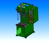
5t hydraulic press
...5t hydraulic press
3dexport
5t hydraulic press
3d_export
$6

e15 hydraulic station
...e15 hydraulic station
3dexport
e15 hydraulic station
3d_export
$45

hydraulic excavator
...excavator
3dexport
3d model excavator.blender 2.93. hight polygon. hydraulic excavator model with pbr textures. .obj .fbx .blend
turbosquid
$90

Hydraulic pump
...d
royalty free 3d model hydraulic pump for download as sldas on turbosquid: 3d models for games, architecture, videos. (1245128)
turbosquid
$1

Hydraulic Cylinder
...oyalty free 3d model hydraulic cylinder for download as blend on turbosquid: 3d models for games, architecture, videos. (1515778)
turbosquid
$5

Hydraulic Lift
...alty free 3d model hydraulic lift for download as obj and fbx on turbosquid: 3d models for games, architecture, videos. (1443188)
turbosquid
$20

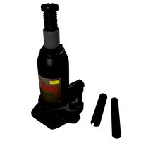
Hydraulic jack
...d model hydraulic jack for download as c4d, fbx, dae, and obj on turbosquid: 3d models for games, architecture, videos. (1699409)
turbosquid
$49

Platform Hydraulic
... available on turbo squid, the world's leading provider of digital 3d models for visualization, films, television, and games.
turbosquid
$39
Hydraulic Jack
... available on turbo squid, the world's leading provider of digital 3d models for visualization, films, television, and games.
Titan
design_connected
$18

Titan
...titan
designconnected
original btc titan computer generated 3d model.
3d_ocean
$25
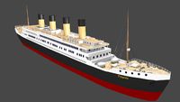
RMS Titanic
...rms titanic
3docean
ship steamer titanic
3d model of the rms titanic
turbosquid
$49
Titan
...quid
royalty free 3d model titan for download as obj and ztl on turbosquid: 3d models for games, architecture, videos. (1314276)
turbosquid
$8

Titan
...d
royalty free 3d model titan for download as , fbx, and obj on turbosquid: 3d models for games, architecture, videos. (1545505)
3d_export
$15

eren yeager titan from attack on titan
...eren yeager titan from attack on titan
3dexport
3d model of eren titan
3d_export
$5
titanic new
...titanic new
3dexport
titanic 3d model normal quality for animation
3d_export
$100
Titan 3D Model
...titan 3d model
3dexport
silo launcher rocket titan
titan 3d model acquarius 37854 3dexport
3d_ocean
$25

Titan
...nfs nfshs one ps ps1 psone rod speed sports stakes titan transport vehicle
quality exterior and low polygon interior concept car.
3ddd
$1

Titanic Lamp(table)
...titanic lamp(table)
3ddd
titanic lamp(table)
turbosquid
$10

Titan chair
...osquid
royalty free 3d model titan chair for download as max on turbosquid: 3d models for games, architecture, videos. (1301533)
6
3d_export
$18

tulip 6
...tulip 6
3dexport
tulip 6
3d_export
$5
hinge 6
...hinge 6
3dexport
hinge 6
3ddd
$1

MASIERO / FLASHWOOD STL 6 + 6
...6
3ddd
masiero
торшер flashwood stl 6 + 6 фабрики masiero
http://www.masierogroup.com/c87_697/it/flashwood%20stl%206%20+%206.ashx
turbosquid
$110

Atmos Cannon 2000 6*6
...yalty free 3d model atmos cannon 2000 6*6 for download as skp on turbosquid: 3d models for games, architecture, videos. (1528591)
turbosquid
$1

ae 6 6 electric locomotive
... free 3d model ae 6 6 electric locomotive for download as obj on turbosquid: 3d models for games, architecture, videos. (1707537)
turbosquid
$39

A-6
... available on turbo squid, the world's leading provider of digital 3d models for visualization, films, television, and games.
3ddd
$1
6 ковров
...6 ковров
3ddd
ковры , ковер
6 ковров
turbosquid
$12

Calligraphic Digit 6 Number 6
...hic digit 6 number 6 for download as max, obj, fbx, and blend on turbosquid: 3d models for games, architecture, videos. (1389336)
turbosquid
$19

Case For Phone 6 Girl 6
... available on turbo squid, the world's leading provider of digital 3d models for visualization, films, television, and games.
turbosquid
$35

Iphone 6 & 6 Plus All
... available on turbo squid, the world's leading provider of digital 3d models for visualization, films, television, and games.
Project
3d_export
$7
project
...project
3dexport
project
3d_export
$20
Project
...project
3dexport
design_connected
$16

Project Chair
...project chair
designconnected
rex kralj project chair computer generated 3d model. designed by žitnik, marjan.
3ddd
$1

lectric Project
...настроены. сетка очень плотная.
доступно только для группы "profi"
про группу "profi" можно прочитать в чаво
3d_ocean
$19

Soon project
...kup. made in 3ds max 2013 1- 3dsmax with vray render included material and light 2- obj file 3- fbx file hope you like it plea...
turbosquid
$49

Joint | Project
...squid
royalty free 3d model joint | project for download as on turbosquid: 3d models for games, architecture, videos. (1297983)
turbosquid
$11

house project
...bosquid
royalty free 3d model house project for download as on turbosquid: 3d models for games, architecture, videos. (1672482)
turbosquid
$450
University project
...
royalty free 3d model university project for download as rvt on turbosquid: 3d models for games, architecture, videos. (1463354)
turbosquid
$30
smart projecter
...lty free 3d model smart projecter for download as max and obj on turbosquid: 3d models for games, architecture, videos. (1236214)
3d_export
$5
project drawing
...project drawing
3dexport
project drawing and 3d model<br>format jpg sldprt dwg<br>by 3d make
Part
3d_export
$5

Parts
...parts
3dexport
parts
3d_export
$5

Part
...part
3dexport
part
3d_export
$5

Part
...part
3dexport
machine part
3d_export
$65

Part
...part
3dexport
simple rendering of the scene file
3d_export
$65

Part
...part
3dexport
simple rendering of the scene file
3d_export
$30

fan part
...fan part
3dexport
this is a part of fan of pedastal
3d_export
$10
machine parts
...machine parts
3dexport
3d part modeling work ,contact for 3d work
turbosquid
$59

Mechanical Part
...id
royalty free 3d model mechanical part for download as c4d on turbosquid: 3d models for games, architecture, videos. (1410833)
turbosquid
$17
Road parts
...bosquid
royalty free 3d model road parts for download as 3ds on turbosquid: 3d models for games, architecture, videos. (1192967)
turbosquid
$9

Cutter Parts
...squid
royalty free 3d model cutter parts for download as stl on turbosquid: 3d models for games, architecture, videos. (1220010)