Thingiverse
Project: Prusa i4 Single Z-axis motor Modification by ZahirSaleh
by Thingiverse
Last crawled date: 3 years, 1 month ago
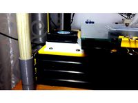
Project: Prusa i4 Single Z-axis motor Modification
Why:
100% synchronization of the two z- axes screws
No loss in horizontal calibration of the z-axis even when one z-axis screw turned by hand accidentally.
Free one z-axis driver for expansions such as a second extruder.
Get a spare stepper motor may be?
Use the spare stepper (and freed driver) for extra extruder??? (will upload this soon)
Steps:
1) Download and Print all the stl files attached.
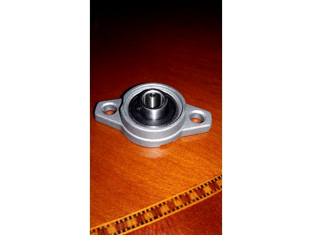
2) Remove the bearing from the original holding block by tapping it off gently with a blunt object. Link:https://www.aliexpress.com/item/Free-shipping-10pcs-lot-8mm-diameter-zinc-alloy-bearing-housing-KFL08-FL08-K08-flange-bearing-with/32363611626.html?spm=2114.01010208.3.2.UmD2Mk&ws_ab_test=searchweb0_0,searchweb201602_5_10065_10068_10136_10137_10138_10060_10062_10141_10056_10055_10054_10059_10099_10103_10102_10096_10148_10052_10053_10050_10107_10142_10051_10143_10084_10083_10080_10082_10081_10110_10111_10112_10113_10114_130_10037_10032_10078_10079_10077_10073_10070_10123_10124,searchweb201603_4,afswitch_1,ppcSwitch_5,single_sort_0_default&btsid=2204374a-198b-4e82-af4e-a0d7348ef356&algo_expid=f5950bc5-8388-4842-bfec-157112b24ff1-0&algo_pvid=f5950bc5-8388-4842-bfec-157112b24ff1
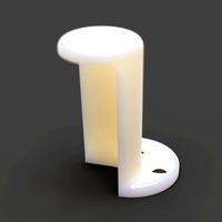
3) Fit the bearing in the bottom bearing holder printed from the stl.
4) Open and remove one z axis motor and disconnect it from the motherboard, this also frees the driver for other use.
5) Now replace the motor with the bottom bearing holder assembled in the steps above.
6) Use the gab screws to secure the z-axis screw to the bearing
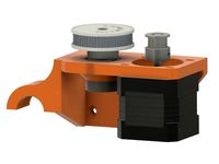
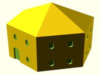
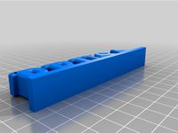
7) Print two sets of the pulley and their covers and fit together
8) Drive your z-axis to the top manually with your hand,
9) Fit the two pulleys and secure in place with two screws (pulleys with holes for screw and nut) pulleys are tight fit and will require some force to be fit.
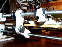
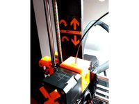
10) Print and fit the two top bearing holders and fit the bearings in to them.
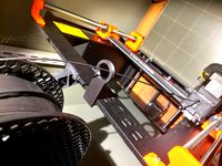
11) Fit these holders on top of the installed pulleys (see pictures for clarity)
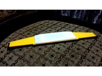
12) With the z-axis now at top most (probably touching the installed pulleys) measure a length of timing belt to fit tightly and then reduce the length by about 3 teeth. The belt can be got from here Link:https://www.aliexpress.com/item/POWGE-GT2-timing-belt-width-6mm-Rubber-2GT-6mm-used-in-linear-drive-Small-Backlash-2GT/2039635559.html?spm=2114.13010608.0.0.TyqFC7
13) Now splice the belt to form a ring as per this procedure Link: https://www.youtube.com/watch?v=lT8eHz4tWyc
Notice that I did not use the kit i the video and I used standard leather glue, worked well. However, the procedure in the video produces a much cleaner result. Try it. You may also search for other splicing videos on Youtube. Its free, learn ;o)
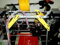
14) Once the spliced belt cures lower the z axis down manually and fit the belt.
15) Drive the axis up manually again. Since the belt was reduced a bit (by about 3 teeth), the movement of the z-axis upward now provides full tension to the belt.
16) Tighten the Z-axis top bearing holders in place on the top rail to permanently secure the top bearing holders and tension the belt.
Modifying the Merlin Firmware:
17) Load your current firm ware in your favorite arduino IDE.
18) Open the file CONFIGURATION_ADV.h
19) look for the line below and comment it out (i.e. add // slashes before it as below)
20) //#define Z_DUAL_STEPPER_DRIVERS //Zahir - changed to use this driver for extruder 2
21) You may add custom comments as above to remind you in the future why you commented out the line.
22) It is done. Enjoy!
Why:
100% synchronization of the two z- axes screws
No loss in horizontal calibration of the z-axis even when one z-axis screw turned by hand accidentally.
Free one z-axis driver for expansions such as a second extruder.
Get a spare stepper motor may be?
Use the spare stepper (and freed driver) for extra extruder??? (will upload this soon)
Steps:
1) Download and Print all the stl files attached.
2) Remove the bearing from the original holding block by tapping it off gently with a blunt object. Link:https://www.aliexpress.com/item/Free-shipping-10pcs-lot-8mm-diameter-zinc-alloy-bearing-housing-KFL08-FL08-K08-flange-bearing-with/32363611626.html?spm=2114.01010208.3.2.UmD2Mk&ws_ab_test=searchweb0_0,searchweb201602_5_10065_10068_10136_10137_10138_10060_10062_10141_10056_10055_10054_10059_10099_10103_10102_10096_10148_10052_10053_10050_10107_10142_10051_10143_10084_10083_10080_10082_10081_10110_10111_10112_10113_10114_130_10037_10032_10078_10079_10077_10073_10070_10123_10124,searchweb201603_4,afswitch_1,ppcSwitch_5,single_sort_0_default&btsid=2204374a-198b-4e82-af4e-a0d7348ef356&algo_expid=f5950bc5-8388-4842-bfec-157112b24ff1-0&algo_pvid=f5950bc5-8388-4842-bfec-157112b24ff1
3) Fit the bearing in the bottom bearing holder printed from the stl.
4) Open and remove one z axis motor and disconnect it from the motherboard, this also frees the driver for other use.
5) Now replace the motor with the bottom bearing holder assembled in the steps above.
6) Use the gab screws to secure the z-axis screw to the bearing
7) Print two sets of the pulley and their covers and fit together
8) Drive your z-axis to the top manually with your hand,
9) Fit the two pulleys and secure in place with two screws (pulleys with holes for screw and nut) pulleys are tight fit and will require some force to be fit.
10) Print and fit the two top bearing holders and fit the bearings in to them.
11) Fit these holders on top of the installed pulleys (see pictures for clarity)
12) With the z-axis now at top most (probably touching the installed pulleys) measure a length of timing belt to fit tightly and then reduce the length by about 3 teeth. The belt can be got from here Link:https://www.aliexpress.com/item/POWGE-GT2-timing-belt-width-6mm-Rubber-2GT-6mm-used-in-linear-drive-Small-Backlash-2GT/2039635559.html?spm=2114.13010608.0.0.TyqFC7
13) Now splice the belt to form a ring as per this procedure Link: https://www.youtube.com/watch?v=lT8eHz4tWyc
Notice that I did not use the kit i the video and I used standard leather glue, worked well. However, the procedure in the video produces a much cleaner result. Try it. You may also search for other splicing videos on Youtube. Its free, learn ;o)
14) Once the spliced belt cures lower the z axis down manually and fit the belt.
15) Drive the axis up manually again. Since the belt was reduced a bit (by about 3 teeth), the movement of the z-axis upward now provides full tension to the belt.
16) Tighten the Z-axis top bearing holders in place on the top rail to permanently secure the top bearing holders and tension the belt.
Modifying the Merlin Firmware:
17) Load your current firm ware in your favorite arduino IDE.
18) Open the file CONFIGURATION_ADV.h
19) look for the line below and comment it out (i.e. add // slashes before it as below)
20) //#define Z_DUAL_STEPPER_DRIVERS //Zahir - changed to use this driver for extruder 2
21) You may add custom comments as above to remind you in the future why you commented out the line.
22) It is done. Enjoy!
Similar models
grabcad
free

Geared motor drive
...ng, journal bearing, driver and driven pulleys connected by a belt drive. the base is a support to the motor and journal bearing.
thingiverse
free
Piper 2 Sub 500mm Z belt drive by catspider
...ings
1 motor coupler
2 washers to act as spacers between the pulley and bearing and motor coupler and bearing.
1 160mm gt2 belt.
thingiverse
free

Anet A8 single motor Z axis drive by osadchy
...he original 400 to 800)
hope i included everything here. if you find anything missing, please comment and i'll answer/update.
thingiverse
free

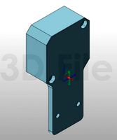
Prusa i4 Z Axis bearing mount by briangilbert
...27mm with and additional screw hole for the vertical 20x20.
both of these brackets are designed to be used with flanged bearings.
thingiverse
free

Anet A8 Z-Axis rework by smallindine
...ginal, this plate replaces that support.
the top z screw holder is based on this thing: https://www.thingiverse.com/thing:1858435
thingiverse
free

Hypercube 300 Single Z-Axis Motor Mount by salfter
...lleys, a 5-mm-bore gt2 pulley, a couple of 3-mm-bore gt2 smooth idlers, a 3-mm-bore toothed idler, and a 1220mm closed-loop belt.
thingiverse
free

Dual GT2 Belt Driven Z Axis for Hypercube by n9jcv
...or placement of pulleys (i just printed plastic washers not critical).
again i am 100% happy with the performance of the z now.
thingiverse
free

16_to_80 belt extruder by papa5468
...uder is a 5mm x 30mm screw and three nuts with blue thread lock . the belt is a 2gt-6 closed loop rubber length 200mm, width 6mm.
thingiverse
free
Y bearing bracket by Alekseev_D
...lastic pulley to another carrier (axle bearing to move down a bit.)
pros: a bearing 608, an increase in movement along the z axis
thingiverse
free

Belt Tensioner by chercus
...belt tensioner by chercus
thingiverse
z-axis belt tensioner for x5s for use with 1170mm belt and two 60t pulleys
Zahirsaleh
thingiverse
free

Prusa i4 Chassis fan holder by ZahirSaleh
...prusa i4 chassis fan holder by zahirsaleh
thingiverse
use for mounting a fan on prusa i4 base.
thingiverse
free
Prusa i4 LCD Screen Cover by ZahirSaleh
... and fits snugly! no screws required, just place and snap in to place. covers both openings, for the lcd and for the knob. enjoy!
thingiverse
free

Prusa i4 Bed leveling "Easy Knob” by ZahirSaleh
...rd skirt/brim is printing. print these knobs in abs as they need to withstand say up to 110deg cen of bed heat without deforming.
thingiverse
free

From Prusa i4 to Prusa Z by ZahirSaleh
...ying so that i send you a complete package containing all the necessary modification pieces and firmware in a flash, write to me.
thingiverse
free
Prusa i4 Cooling system modification by ZahirSaleh
...ll need to remove the fan connector plastic using a pin (figure it out) and return it back once the wires pass through the base.
I4
3d_export
$69

bmw-i4
...vertisements or games corona render and materials all textures include in *.rar files lighting setup is not included in the file!
3ddd
$1

i4 Mariani Oyster
... oyster
кресло. i4 mariani, модель oyster.http://www.i4mariani.it/ing/home.html
3ddd
$1

кресло i4 Mariani blob
...кресло i4 mariani blob
3ddd
i4 mariani , blob
кресло i4 mariani blob
3ddd
$1

i4 Mariani Apollo
...i4 mariani apollo
3ddd
i4 mariani
включен файл для 3ds max 2012.
3ddd
$1
i4 MARIANI / manta
...i4 mariani / manta
3ddd
i4 mariani
итальянское кожаное кресло в двух цветовых решениях.
3ddd
$1
i4 Marinari - Slide
...modern design sideboard from i4 marinari. i couldn't find any dimensions of the product, so i designed it to my needs.
enjoy.
3d_export
$69

bmw-i4 m50
...vertisements or games corona render and materials all textures include in *.rar files lighting setup is not included in the file!
3ddd
$1

i4 Mariani SISSI Chair
...i4 mariani sissi chair
3ddd
i4 mariani
3ds max 2010.v-ray 2.40.03.file formats fbx,obj.i4 mariani sissi chair
3ddd
$1

i4 Mariani SISSI Chair
...i4 mariani sissi chair
3ddd
i4 mariani
3ds max 2010.v-ray 2.40.03.file formats fbx,obj,3ds.i4 mariani sissi chair
cg_studio
$25
i4 mariani Sofa Kate3d model
...a kate furniture
.fbx .obj .max - i4 mariani sofa kate 3d model, royalty free license available, instant download after purchase.
Modification
turbosquid
$12
AKMS (AK47 modification)
... available on turbo squid, the world's leading provider of digital 3d models for visualization, films, television, and games.
turbosquid
$79
BusTransForm - Modif Bus Thailand
...d model bustransform - modif bus thailand for download as obj on turbosquid: 3d models for games, architecture, videos. (1383303)
3d_export
$25

mitsubishi evo 9 modification
...mitsubishi evo 9 modification
3dexport
evo 9 has been modified with a nice and elegant look.
3d_ocean
$25

Dart Vader (modificated helm)
...niforms, as well as anatomical model of the character itself. the model is divided into groups for further editing. primarily ...
turbosquid
$15

FN SCAR-H modification low-poly game ready
...fication low-poly game ready for download as ma, obj, and fbx on turbosquid: 3d models for games, architecture, videos. (1386384)
3d_export
$5

sphere light
...sphere light
3dexport
the socket and light are modifables
3d_export
$5

Fabulous chest
...chest 3dexport fabulous chest for your game or further modification ...
3d_export
free

cold coffee
...cold coffee 3dexport cold coffee can. any required modification will be done at...
3d_ocean
$12

Cartoon Dump or Sand Truck
...already rig low poly modifier still in stack for modification unwrap uvw for material and colour...
3d_ocean
$12

Cartoon Cement Mixer Truck
...already rig low poly modifier still in stack for modification unwrap uvw for material and colour...
Prusa
turbosquid
$2
Frame Filament Guide Clip-On for Prusa Mk3
...rame filament guide clip-on for prusa mk3 for download as stl on turbosquid: 3d models for games, architecture, videos. (1634730)
3d_export
free
prusa i3 mk3s laser mount for opt lasers
...to learn more about the blue laser technology that conceived the cutting and engraving laser heads from opt lasers, please visit:
turbosquid
free
Prusa small printer adapter holder
...er for download as ipt, skp, dwg, dxf, fbx, ige, obj, and stl on turbosquid: 3d models for games, architecture, videos. (1642936)
3d_export
$30

geisha by jonathan adler
...** i did a 3d printing test in the prusa software, you can find it among the attached images.<br>exchange:<br>.blend...
thingiverse
free

Prusa without Prusa (rc2) by madless
...prusa without prusa (rc2) by madless
thingiverse
just the main part of prusa rc2 faceshield, without writing.
enjoy :)
thingiverse
free
Prusa by acejbc
...prusa by acejbc
thingiverse
prusa knob info
m3 8mm screw
thingiverse
free
Prusa house
...prusa house
thingiverse
how prusa house could look like...
thingiverse
free

Prusa Mk2 "Fake Prusa" LCD cover by anraf1001
...r by anraf1001
thingiverse
version of prusa's lcd cover with "fake prusa" instead of "original prusa"
thingiverse
free
Prusa stabilizator by gutiueugen
...prusa stabilizator by gutiueugen
thingiverse
prusa stabilizator
thingiverse
free
Keychain Prusa by rbarbalho
...keychain prusa by rbarbalho
thingiverse
keychain with text prusa.
Axis
3ddd
$1

Мария Axis
...
3ddd
кухня , классическая , axis
модель кухни.
3d_export
$22
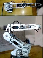
Axis robot 6-axis robotic arm
...ing parts drawings, standard parts purchased parts list, can be produced directly according to the drawings, welcome to download!
3ddd
free

Versatile Axis
...ddd
nexus , плитка
http://bvtileandstone.com/ceramic-porcelain/versatile-axis/
3d_export
$19
robot 2 axis
...robot 2 axis
3dexport
robot 2 axis
turbosquid
$40
Axis R5F
... available on turbo squid, the world's leading provider of digital 3d models for visualization, films, television, and games.
turbosquid
$40
Axis S5F
... available on turbo squid, the world's leading provider of digital 3d models for visualization, films, television, and games.
turbosquid
$30
Axis Athlon
... available on turbo squid, the world's leading provider of digital 3d models for visualization, films, television, and games.
turbosquid
$10

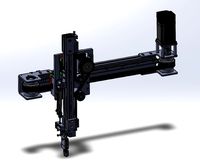
Linear Axis
... available on turbo squid, the world's leading provider of digital 3d models for visualization, films, television, and games.
3d_export
$15

drawing axis
...drawing axis
3dexport
simple rendering of the scene file
3ddd
$1

versatile axis ARC
...versatile axis arc
3ddd
versatile , плитка
versatile axis arc red dot design award
Z
3d_export
$5
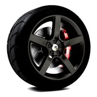
nissan z
...nissan z
3dexport
nissan z
3ddd
$1

Vase Z
...vase z
3ddd
vase z
3ddd
$1
полотенцесушить Z
...полотенцесушить z
3ddd
полотенцесушитель
полотенцесушить z
design_connected
free
Z-Chair
...z-chair
designconnected
free 3d model of z-chair designed by karman, aleksei.
design_connected
$11

Z Lamp
...z lamp
designconnected
phillips z lamp computer generated 3d model. designed by kalff, louis.
3d_export
$5
Dragon balls z
...dragon balls z
3dexport
dragon ball z
turbosquid
$20

Fighter Z
...
turbosquid
royalty free 3d model fighter z for download as on turbosquid: 3d models for games, architecture, videos. (1292563)
turbosquid
$9

Pen Z
...pen z
turbosquid
free 3d model pen z for download as obj on turbosquid: 3d models for games, architecture, videos. (1686775)
turbosquid
free
z chair
...z chair
turbosquid
free 3d model z chair for download as max on turbosquid: 3d models for games, architecture, videos. (1410230)
turbosquid
$5

Letter Z
...urbosquid
royalty free 3d model letter z for download as max on turbosquid: 3d models for games, architecture, videos. (1408540)
Motor
archibase_planet
free
Motor
...base planet
motor motor engine engine electric motor
motor wagner n250213 - 3d model (*.gsm+*.3ds) for interior 3d visualization.
archibase_planet
free
Motor
...motor
archibase planet
motor motor engine engine
motor n151112 - 3d model (*.gsm+*.3ds) for interior 3d visualization.
archibase_planet
free
Motor
...motor
archibase planet
motor motor engine engine
motor n150615 - 3d model (*.gsm+*.3ds+*.max) for interior 3d visualization.
turbosquid
$15
Motor
...otor
turbosquid
royalty free 3d model motor for download as on turbosquid: 3d models for games, architecture, videos. (1639404)
3d_ocean
$5
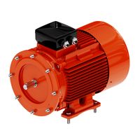
Electric motor
...electric motor
3docean
car electric engine industry motor phase train vehicle
an electric motor enjoy!
3d_ocean
$18
Electric Motor
...electric motor
3docean
electric motor engine machine mover parts
3d model electric motor for hoist crane
turbosquid
$29

Motor
... available on turbo squid, the world's leading provider of digital 3d models for visualization, films, television, and games.
turbosquid
$5
Motor
... available on turbo squid, the world's leading provider of digital 3d models for visualization, films, television, and games.
3d_export
$5
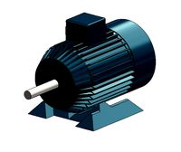
electric motor
...electric motor
3dexport
electric motor use for industrial purposes
3d_export
$5

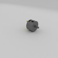
servo motor
...tor
3dexport
it's a simple part of servo motor 0.75kw for used in machines assembly to show specified motor in own project.
Single
3d_export
$5

single sofa single chair
...single sofa single chair
3dexport
single sofa single chair 3d model
3d_export
$5

single sofa single chair
...single sofa single chair
3dexport
single sofa single chair 3d model
3d_export
$5

single fastener
...single fastener
3dexport
single fastener
3ddd
$1
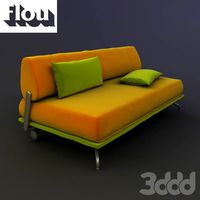
Single FLOU
... sofa , трансформер
диван-трансформер single от итальянского производителя flou
3ddd
$1
bed single
...bed single
3ddd
постельное белье
bed single 190cm*90cm
3ddd
$1

Single Flou
...single flou
3ddd
качественная моделька дивана-трансформера single flou.
3d_ocean
$9
Single sofa
...le sofa
3docean
modern sofa single sofa sofa white sofa.comfortable sofa
single sofa,sofa,modern sofa,white sofa.comfortable sofa
3d_export
free

Single Knife
...single knife
3dexport
a single knife, presumably it was used as one of the throwing knives.
3d_export
free

couch - single
...couch - single
3dexport
low poly single couch with .psd file for personal customization
3d_ocean
$5
Single Sofa
...single sofa
3docean
single sofa made by fabric , wood frame & ss leg
Project
3d_export
$7
project
...project
3dexport
project
3d_export
$20
Project
...project
3dexport
design_connected
$16

Project Chair
...project chair
designconnected
rex kralj project chair computer generated 3d model. designed by žitnik, marjan.
3ddd
$1

lectric Project
...настроены. сетка очень плотная.
доступно только для группы "profi"
про группу "profi" можно прочитать в чаво
3d_ocean
$19

Soon project
...kup. made in 3ds max 2013 1- 3dsmax with vray render included material and light 2- obj file 3- fbx file hope you like it plea...
turbosquid
$49
Joint | Project
...squid
royalty free 3d model joint | project for download as on turbosquid: 3d models for games, architecture, videos. (1297983)
turbosquid
$11

house project
...bosquid
royalty free 3d model house project for download as on turbosquid: 3d models for games, architecture, videos. (1672482)
turbosquid
$450
University project
...
royalty free 3d model university project for download as rvt on turbosquid: 3d models for games, architecture, videos. (1463354)
turbosquid
$30

smart projecter
...lty free 3d model smart projecter for download as max and obj on turbosquid: 3d models for games, architecture, videos. (1236214)
3d_export
$5
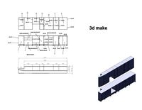
project drawing
...project drawing
3dexport
project drawing and 3d model<br>format jpg sldprt dwg<br>by 3d make