Thingiverse
Power Supply, Raspberry Pi, Relay Module, Fan Case by anhtien
by Thingiverse
Last crawled date: 3 years ago
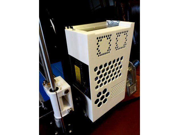
It's a long name but it has multiple uses: cooling down the AC/DC power supply, switching on/off the AC/DC power supply remotely. It is also a Raspberry Pi / Relay Module case.
You can refer to the included connection diagram to see how things are connected inside this case.
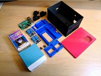
Hardware:
Raspberry Pi with Octoprint preloaded and ready to be accessed from a Web Browser. If not, search online to see how to set it up.
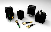
A relay module, one channel is good for this purpose but I have 2 channel module installed because I will want to remotely turning on/off other devices (light, music, or anything that will connect to my “future” power bar). With one channel relay module, everything could be turned on/off together with the 3D printer. However, controlling other devices separately might be more practical such as leaving music on and keep the 3D printer off to cool it down after so many hours of usage. The price is about the same for 2 or 1 channel relay module.
A terminal strip (optional but I recommend it for ease of connectivity and power distribution). Please use the electrical ring connectors at all connections if you can, don't be cheap on this because one loose wire can cause a very damaging spark.
Two 40mm fan, 12vdc type of course.
Also need 3 x M3 screws and 2 nuts on top right, 2 screws and 2 nuts on the bottom right (or #6 3/8” machine screws worked too)
Use wood screws (such as #6 3/8”) to fasten terminal strip to the frame. Remove existing M3 screw from the power supply (top left) and replace with longer M3 screw (spare from the Anet A8).
The design could fit different type of Raspberry Pi and/or Relay Module, if you can not snap the board(s) in you could use tie-wrap through the honeycomb holes, double-sided tape or crazy glue to secure the Raspberry and Relay Module to the frame.
Follow the attached wiring diagram to connect the components together, make sure you orient the Raspberry Pi to have the network cable toward the back or else the network cable might get caught with the X-axis / Z-axis bars & rod. Also connect the fans with label pointing outside to suck the hot air out of the power supply and not blowing dust into it.
Software:
Octopi comes with GPIO already pre-installed, use SSH to login using pi username. To check if it’s available enter command:
gpio readall
If it comes back with information then you are good to go. If not, check wiringpi.com to see how to install.
Wiring Diagram:
In order for the octopi to control the relay, the “live” wire from main power should go to the “live” port #1 on the AC/DC power supply. The neutral line from main power goes to COM port on the relay module. Connect a new neutral line from NO (Normally Open) port on the relay module to the power supply Neutral port #2. Connect the ground straight from main power to the AC/DC power supply ground port #3. A side note about my AC/DC 12vdc power supply, I think the Anet A8 comes with incorrect internal wiring and I “had” to use my neutral line as “COM” line, it should really be the “hot/live” wire to be used as COM line. Well, since I don’t have another 12vdc power supply I can’t verify if All Anet A8 are like that or not. Anyway, the point is to have the Hot wire from main power to the relay’s COM port, then Normally Open (NO) port goes to AC/DC Hot wire. I just show what works for me, you might have to switch live and neutral wires if it does not work for you.
The Raspberry Pi uses the WiringPi connection scheme so check it out and use the proper GPIO pin. To demonstrate the pinout scheme, if you have the same Raspberry Pi Rev B as mine, then the 5vdc is the first pin on the outer row, ground is the third pin, and GPIO 1 is on the 6th pin. Those are NOT the actual pin number, those are for locating where they are on the board. The actual pin for 5vdc is header pin #2, ground is header pin #6, and GPIO is header pin #12. In fact the “gpio readall” command shows the pinout for your board, dont' use the BCM pinout.
Once logged in, edit the file .bashrc and add the following two lines:
alias a8on='gpio mode 1 out;gpio write 1 0'
alias a8off='gpio write 1 1;gpio mode 1 in'
Save and exit, then enter command “source .bashrc” to activate it. If you do your wiring properly, you should be able to enter command “a8on” and see the unit goes up, “a8off” to see it turned off.
Print settings:
I used Repetier to print, needed to move object 7mm on X-axis to the right to center it. Maybe it’s my Repetier setup that was incorrect.
Slicer configuration:
Print settings:
Layer high 0.2mm, Infill 30%, Speed 37mms, Do generate Support Material.
Filament settings: PLA 1.75mm, depending on your filament I set mine to 215 deg for extruder, 65 deg for hot bed.
Update 1: Adding version 3 with stronger and thicker wall (4mm instead of 2mm) and the thin version with higher retaining tabs for the relay module (v2a)
You can refer to the included connection diagram to see how things are connected inside this case.
Hardware:
Raspberry Pi with Octoprint preloaded and ready to be accessed from a Web Browser. If not, search online to see how to set it up.
A relay module, one channel is good for this purpose but I have 2 channel module installed because I will want to remotely turning on/off other devices (light, music, or anything that will connect to my “future” power bar). With one channel relay module, everything could be turned on/off together with the 3D printer. However, controlling other devices separately might be more practical such as leaving music on and keep the 3D printer off to cool it down after so many hours of usage. The price is about the same for 2 or 1 channel relay module.
A terminal strip (optional but I recommend it for ease of connectivity and power distribution). Please use the electrical ring connectors at all connections if you can, don't be cheap on this because one loose wire can cause a very damaging spark.
Two 40mm fan, 12vdc type of course.
Also need 3 x M3 screws and 2 nuts on top right, 2 screws and 2 nuts on the bottom right (or #6 3/8” machine screws worked too)
Use wood screws (such as #6 3/8”) to fasten terminal strip to the frame. Remove existing M3 screw from the power supply (top left) and replace with longer M3 screw (spare from the Anet A8).
The design could fit different type of Raspberry Pi and/or Relay Module, if you can not snap the board(s) in you could use tie-wrap through the honeycomb holes, double-sided tape or crazy glue to secure the Raspberry and Relay Module to the frame.
Follow the attached wiring diagram to connect the components together, make sure you orient the Raspberry Pi to have the network cable toward the back or else the network cable might get caught with the X-axis / Z-axis bars & rod. Also connect the fans with label pointing outside to suck the hot air out of the power supply and not blowing dust into it.
Software:
Octopi comes with GPIO already pre-installed, use SSH to login using pi username. To check if it’s available enter command:
gpio readall
If it comes back with information then you are good to go. If not, check wiringpi.com to see how to install.
Wiring Diagram:
In order for the octopi to control the relay, the “live” wire from main power should go to the “live” port #1 on the AC/DC power supply. The neutral line from main power goes to COM port on the relay module. Connect a new neutral line from NO (Normally Open) port on the relay module to the power supply Neutral port #2. Connect the ground straight from main power to the AC/DC power supply ground port #3. A side note about my AC/DC 12vdc power supply, I think the Anet A8 comes with incorrect internal wiring and I “had” to use my neutral line as “COM” line, it should really be the “hot/live” wire to be used as COM line. Well, since I don’t have another 12vdc power supply I can’t verify if All Anet A8 are like that or not. Anyway, the point is to have the Hot wire from main power to the relay’s COM port, then Normally Open (NO) port goes to AC/DC Hot wire. I just show what works for me, you might have to switch live and neutral wires if it does not work for you.
The Raspberry Pi uses the WiringPi connection scheme so check it out and use the proper GPIO pin. To demonstrate the pinout scheme, if you have the same Raspberry Pi Rev B as mine, then the 5vdc is the first pin on the outer row, ground is the third pin, and GPIO 1 is on the 6th pin. Those are NOT the actual pin number, those are for locating where they are on the board. The actual pin for 5vdc is header pin #2, ground is header pin #6, and GPIO is header pin #12. In fact the “gpio readall” command shows the pinout for your board, dont' use the BCM pinout.
Once logged in, edit the file .bashrc and add the following two lines:
alias a8on='gpio mode 1 out;gpio write 1 0'
alias a8off='gpio write 1 1;gpio mode 1 in'
Save and exit, then enter command “source .bashrc” to activate it. If you do your wiring properly, you should be able to enter command “a8on” and see the unit goes up, “a8off” to see it turned off.
Print settings:
I used Repetier to print, needed to move object 7mm on X-axis to the right to center it. Maybe it’s my Repetier setup that was incorrect.
Slicer configuration:
Print settings:
Layer high 0.2mm, Infill 30%, Speed 37mms, Do generate Support Material.
Filament settings: PLA 1.75mm, depending on your filament I set mine to 215 deg for extruder, 65 deg for hot bed.
Update 1: Adding version 3 with stronger and thicker wall (4mm instead of 2mm) and the thin version with higher retaining tabs for the relay module (v2a)
Similar models
grabcad
free

Bracket for Raspberry Pi 3 with LM2596 DC-DC step down converter module
...lm2596 dc-dc step down converter module. the lm2596 module is used to supply power for raspberry from switching mode power supply
thingiverse
free

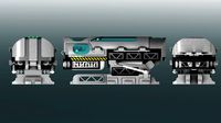
Anet A8 PSU cover with switch, relays, fan and OctoPrint
...additional details) one power switch (note: there are two similar versions of this switch, one with countersink screw heads...
thingiverse
free
OctoPrint Dual instances control box by Sp4wN
...fit in the box, or you can buy a similar one:https://www.aliexpress.com/item/ugreen-usb-2-0-type-a-male-to-b-male-printer-cable-sync-data-charger-cable/32416310263.html dupont wires:https://www.aliexpress.com/item/wavgat-dupont-line-120pcs-20cm-male-to-male-male-to-female-and-female-to-female-jumper/32501238474.html usb hub i have used is...
thingiverse
free

Raspberry Pi GPIO Power Blocker for Prusa by Shwalamazula
...spberry-pi-zero-w-preparation-and-installation_2180
power pins are blocked as well. this is for externally-powered raspberry pis.
thingiverse
free

Zixtec LM2596 DC to DC Converter, Power Supply Step Down Module
...px_yo_dt_b_asin_title_o01_s00?ie=utf8&psc=1
i will just use a dab of hot glue to secure the box to the bottom of the printer.
thingiverse
free

Versatile Power Supply Cover/Enclosure
... the power supply into the case (the wires will be squeezed into the remaining area).
secure with m3 screws on the back and side.
thingiverse
free

Anet A8 Power Supply Cover incl. fused C-14 power socket, 2 channel Relais and RS-15-5 5v Power supply by caesar_1111
...)
as always i included the freecad model.
caesar
ps: be careful when clipping in the rs-15-5 since the clips as somehow fragile.
thingiverse
free

Raspberry Power Supply by Joeend11
...is: 5v 3a dc/dc converter with usb port, 7-24 input voltage kis3r33s step-down module. sellers may be found by any search engine.
thingiverse
free
Relaybox for Raspberry Pi/Arduino by Dslp
...o 2.1 mm dc sockets are attached to the side and the required power supply units can be connected. i also used m3 thread inserts.
thingiverse
free

Relay Control OctoPrint Wanhao i3 by Jeffeb3
...print can keep on doing whatever it was doing before calling that script, wihtout waiting for the sleep or the command to finish.
Anhtien
thingiverse
free

Tabletop 40mm Fan by anhtien
...y anhtien
thingiverse
this simple 40mm fan frame design comes with 2 flavors, nothing fancy. just clip it to the 12vdc adapter.
thingiverse
free
Android / iPhone stand by anhtien
...t a generic smart phone stand, the slot's width is 19mm. print with 50mms speed and 30% infill, support generation required.
thingiverse
free
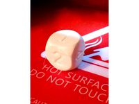
Calibration Dice by anhtien
...e roman numerals version.
i printed it using the repetier default setup (60mms speed, 20% infill), 200deg extruder 50deg hot bed.
thingiverse
free
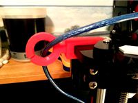
Spaceship Filament / Cable Guide by anhtien
...nt to be another filament guide but i made it large enough to be used as my usb cable guide. it kinda looks like a spaceship :-)
thingiverse
free

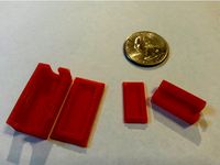
Screw Washers / Spacers by anhtien
...u just print the sizes you need.
add a brim of 5mm when printing if required
update1: added v1 with more clearance between copies
thingiverse
free

Big mouth Funnels by anhtien
...to the flask. one is 33mm wide, the other 43mm wide.
they were designed thin to save on filament.
update 1: added a 50mm funnel.
thingiverse
free
Teeny Tiny Boxes by anhtien
... for tight fit, once snapped in you might need a knife or flat screw driver to take those off. they certainly won't fly away.
thingiverse
free

Rod Support for the Spool Holder by anhtien
...erse.com/thing:2512609). this is probably more useful for the long rod holding many spools which might bend due to heavy weight.
thingiverse
free

360w 12vdc Power Supply Cover by anhtien
...upply. the screw holes are for m4 screws but i have #6-32 3/8 screws and nuts and they fit too (5 screws and 2 nuts are needed).
thingiverse
free
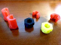
T8 threaded rod spacers by anhtien
...s good to snap in the middle of the rod, also comes with the extra long version. the full nut version is for the end of the rod.
Relay
turbosquid
$50
Relay Spaceship
... model relay spaceship for download as skp, 3ds, dae, and obj on turbosquid: 3d models for games, architecture, videos. (1655800)
3ddd
$1

Scavolini / Grand Relais
...scavolini / grand relais
3ddd
scavolini
scavolini модель grand relais дизайн gianni pareschi
3ddd
$1
Сантехника Globo Relais
... унитаз , зеркало
сантехника globo relais
умывальник,зеркало,унитаз.
3d_export
$8
relay automatic assembly line
...relay automatic assembly line
3dexport
relay automatic assembly line
3ddd
free

Унитаз и биде Relais
... биде , унитаз
унитаз art.re001 bi и биде art.re009 bi
turbosquid
free

Relay 8 pin
... available on turbo squid, the world's leading provider of digital 3d models for visualization, films, television, and games.
cg_studio
$110
Power relay station3d model
...el
cgstudio
.3ds .fbx .max .obj - power relay station 3d model, royalty free license available, instant download after purchase.
3ddd
$1

Стол обеденный -Scavolini- Grand Relais
...s
3ddd
обеденный , scavolini
обеденный стол scavolini - grand relais, в трёх расцветках.
3d_export
$10
relay jd1912 12v 40a with connector
...lowing bodies: 1. relay jd1912 12v 40a - 1 piece; 2. connector housing - 1 piece; 3. terminal with a part of the wire - 4 pieces.
3ddd
free

Globo Relais furnitures
... , раковина
раковина с консолью st070.ne
зеркалоsp070.bi
стакан re0381x
мыльница re0391x
Raspberry
3d_export
free

raspberry
...raspberry
3dexport
3d model of a raspberry. i tried to make it realistic.
turbosquid
$27

Raspberries
...y free 3d model raspberries for download as max, obj, and stl on turbosquid: 3d models for games, architecture, videos. (1354176)
turbosquid
$14

Raspberries
...y free 3d model raspberries for download as max, obj, and fbx on turbosquid: 3d models for games, architecture, videos. (1364663)
3d_export
$5

raspberry pi
...raspberry pi
3dexport
carcasa para la raspberry pi
turbosquid
$99

Raspberry
... available on turbo squid, the world's leading provider of digital 3d models for visualization, films, television, and games.
turbosquid
$10

raspberries
... available on turbo squid, the world's leading provider of digital 3d models for visualization, films, television, and games.
archive3d
free

Raspberries 3D Model
...raspberries 3d model archive3d raspberries raspberry raspberries n300911 - 3d model (*.3ds) for interior 3d...
3d_export
$5

raspberry fruit
...raspberry fruit
3dexport
3d_export
$5

raspberry
...y different sizes. their color ranges from light burgundy to pink. there are formats: obj, 3ds, blend, dae, fbx, mtl.<br>:)
evermotion
$12

raspberries 23 am130
...evermotion raspberries 23 am130 evermotion key 23 food fruit raspberry fruits am130 raspberries highly detailed 3d model of raspberries...
Pi
design_connected
$11

Pi
...pi
designconnected
ligne roset pi chairs computer generated 3d model. designed by thibault desombre.
3d_export
$5
raspberry pi
...raspberry pi
3dexport
carcasa para la raspberry pi
turbosquid
$18

pied
... available on turbo squid, the world's leading provider of digital 3d models for visualization, films, television, and games.
3ddd
$1

Emme pi light
...emme pi light
3ddd
emme pi light
люста emme pi light
3ddd
$1

Emme pi light
...emme pi light
3ddd
emme pi light
бра классическое emme pi light
3ddd
$1

Emme Pi Light
...emme pi light
3ddd
emme pi light
3ddd
$1

Emme Pi Light
...emme pi light
3ddd
emme pi light
design_connected
$16

Pi-Air
...pi-air
designconnected
living divani pi-air lounge chairs computer generated 3d model. designed by harry & camila.
3d_ocean
$15

Manneken Pis
...picting a naked little boy urinating into a fountain’s basin. (wikipedia) the model was sculpted in blender 2.70a rendered wit...
3ddd
$1

Emme pi light
...emme pi light
3ddd
emme pi light
люстра классическая фирма: emme pi light
артикул: 3595/5/cot/12/wh
Supply
turbosquid
$1

supplies
... available on turbo squid, the world's leading provider of digital 3d models for visualization, films, television, and games.
3d_export
$5

black supply
...black supply
3dexport
black supply size: 57.9 x 29.2 x 34 sm
turbosquid
$20

Office Supplies
...lty free 3d model office supplies for download as max and obj on turbosquid: 3d models for games, architecture, videos. (1273636)
3d_export
free

office supplies
...office supplies
3dexport
turbosquid
$8

Supply Drop
...e 3d model supply drop for download as fbx, obj, dae, and stl on turbosquid: 3d models for games, architecture, videos. (1663721)
turbosquid
$75

Supply Helicopter
... available on turbo squid, the world's leading provider of digital 3d models for visualization, films, television, and games.
turbosquid
$65
Supply Ship
... available on turbo squid, the world's leading provider of digital 3d models for visualization, films, television, and games.
turbosquid
$29

Village Supplies
... available on turbo squid, the world's leading provider of digital 3d models for visualization, films, television, and games.
turbosquid
$19

Power Supply
... available on turbo squid, the world's leading provider of digital 3d models for visualization, films, television, and games.
turbosquid
$5

school supplies
... available on turbo squid, the world's leading provider of digital 3d models for visualization, films, television, and games.
Module
turbosquid
$4

Module
...
turbosquid
royalty free 3d model module for download as max on turbosquid: 3d models for games, architecture, videos. (1259603)
3d_export
free

Martian module
...martian module
3dexport
martian module objects 18 textures are missing
design_connected
$39
Kennedee Moduls
...kennedee moduls
designconnected
kennedee moduls computer generated 3d model. designed by massaud, jean-marie.
design_connected
$39

Sayonara Moduls
...sayonara moduls
designconnected
bbb emmebonacina sayonara moduls computer generated 3d model. designed by decursu, giorgio.
design_connected
$27

Togo Moduls
...togo moduls
designconnected
ligne roset togo moduls computer generated 3d model. designed by ducaroy, michel.
design_connected
$34
Nuvola Moduls
...nuvola moduls
designconnected
bonaldo nuvola moduls 2-seater computer generated 3d model. designed by giuseppe viganò.
3d_export
free
Hibernation module
...hibernation module
3dexport
design_connected
$27

Sabi moduls
...sabi moduls
designconnected
paola lenti sabi moduls 2-seater computer generated 3d model. designed by francesco rota.
3d_export
$50

pls concrete module
...pls concrete module
3dexport
pls concrete module<br>pls with concrete mobile mixer module m5
turbosquid
free
Hibernation module
...squid
free 3d model hibernation module for download as blend on turbosquid: 3d models for games, architecture, videos. (1667696)
Fan
3d_export
$5

fan
...fan
3dexport
fan 3d model, table fan, fan, electric fan, ventilator
archibase_planet
free

Fan
...fan
archibase planet
fan large fan
fan out n260707 - 3d model for interior 3d visualization.
archibase_planet
free

Fan
...fan
archibase planet
fan ceiling fan ventilator
fan stealth n300615 - 3d model (*.gsm+*.3ds) for interior 3d visualization.
3d_export
$15

fan
...fan
3dexport
is an ancient fan
3ddd
$1
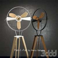
Fan-C-Fan by marco gallegos
...n-c-fan by marco gallegos
3ddd
вентилятор , marco gallegos
fan-c-fan by marco gallegos
3d_export
$10

fan
...fan
3dexport
a detailed fan designed for home or space blowing is now available for only 19.99!
turbosquid
$1

Fan
...fan
turbosquid
free 3d model fan for download as on turbosquid: 3d models for games, architecture, videos. (1427865)
turbosquid
$14

Fan
...fan
turbosquid
royalty free 3d model fan for download as on turbosquid: 3d models for games, architecture, videos. (1415642)
3ddd
$1

Светильник Fan
...светильник fan
3ddd
fan , italamp
светильник fan, производитель italamp
turbosquid
$25

Fan
...fan
turbosquid
royalty free 3d model fan for download as c4d on turbosquid: 3d models for games, architecture, videos. (1483246)
Power
turbosquid
$100

power
...ower
turbosquid
royalty free 3d model power for download as on turbosquid: 3d models for games, architecture, videos. (1421990)
3d_export
$5

Power
...power
3dexport
3d_export
$5

power outlets
...power outlets
3dexport
power outlets
3ddd
$1

lion power
...lion power
3ddd
лев , статуя
lion power gold sculpture
3ddd
$1

Sea Power
...
компас , море , часы
часы с компасом sea power
3ddd
free

Meridiani / Power
...power
3ddd
meridiani , круглый
стол power производитель meridiani, диаметр 120,высота 67
3d_export
$5

Power Surge
...power surge
3dexport
the power surge is a all mesh carnival ride to lower in game part count and lag
turbosquid
$8
Airport Ground Power Unit (AXA Power )
... available on turbo squid, the world's leading provider of digital 3d models for visualization, films, television, and games.
turbosquid
$50

Power Houser
...rbosquid
royalty free 3d model power houser for download as on turbosquid: 3d models for games, architecture, videos. (1333800)
3d_export
$5

power outlet
...power outlet
3dexport
power outlet<br>format file maya 2018, 3d max 2017, obj, fbx
Case
3d_export
$1

case
...case
3dexport
case
archibase_planet
free

Case
...case
archibase planet
showcase show-case glass case
glass-case + cakes - 3d model for interior 3d visualization.
archibase_planet
free

Case
...case
archibase planet
showcase show-case glass case
glass-case for chips - 3d model for interior 3d visualization.
archibase_planet
free
Case
...case
archibase planet
case shelving drawer
case - 3d model for interior 3d visualization.
archibase_planet
free

Case
...case
archibase planet
case rack locker
case - 3d model for interior 3d visualization.
archibase_planet
free
Case
...case
archibase planet
case drawer kitchen furniture
case - 3d model for interior 3d visualization.
archibase_planet
free
Case
...case
archibase planet
case cupboard shelving
glass case - 3d model for interior 3d visualization.
archibase_planet
free

Case
...case
archibase planet
case handbag suitcase
case - 3d model (*.gsm+*.3ds) for interior 3d visualization.
archibase_planet
free

Case
...case
archibase planet
case suitcase
case 5 - 3d model (*.gsm+*.3ds) for interior 3d visualization.
archibase_planet
free
Case
...case
archibase planet
locker case dresser
case - 3d model (*.gsm+*.3ds) for interior 3d visualization.