Thingiverse

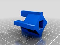
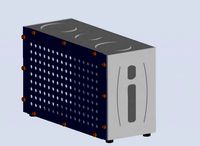
Power Supply Cover by yellowcarboy
by Thingiverse
Last crawled date: 3 years, 1 month ago
Summary
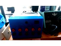
Yet another power supply cover but with a place holder for solid state relay and XT60 connectors.
The original folger 2020 3D printer design has the supplied the power supply (S-260-12) hard wired to the power plug and whenever plugged in the extruder fan would be on. Also the power supply fan was running for no good reason. There is nothing wrong with this solution, I just like to make things more complicated. My goal was to only have the power supply only on during the print and cool down and controlled by the orange Pi (same as the raspberry Pi). The ramps / arduino is powered by the USB connector which allows you to remotely turn on and off the power supply via a 5V dc output. The output activates the solid state relay allowing 120VAC (could be 220VAC) to reach the power supply.
Parts
IEC Power connector. Most common and cost effective ebay and amazon. Link
Solid State relay (25A). Yes 25A is over kill but these are the cheapest solid state relays. Also works with only 3 VDC input if required. Link
XT60 connectors. These connectors should handle 60 Amps but my max load is about 15 A.
Power supply (S-260-12) Size (51 X 114 X 240) Provided from folger 2020 printer kit.
Wiring
If you are not comfortable handling the wiring of 120- 220 VAC then please do not do this project.
Ramps
On my ramps board, the header to control the relay is near the main power connectors. See picture. I connected the ps-on to the negative terminal of the relay and the Vcc connector to the positive terminal on the relay. The ps-on is grounded when on, as it was intended for an ATX power supply I believe.
Power Connector
Follow the picture for the suggested power connect connection on the back. Lastly, instead of connecting the brown wire to the power supply, connect it to the AC side of the replay and add a pigtail from the relay to the power supply.
Slicer Modifications
I had to modify the slicer start and end gcodes to turn the power on and off. I also added a cool down temperature to delay the turn of the power supply to allow the fans to cool the motors and extruder. Note I had to add the M19, M104, M109 codes as the slicer progam would put them before the power on (M80) code.
Start gcodeM80 ; turn on power supply
M190 S[first_layer_bed_temperature]
M104 S[first_layer_temperature]
G28 ; home all axes
G1 Z5 F5000 ; lift nozzle
M109; wait for temperature to reach
End gcodeM106 255 ; turn fan back on
M104 S0 ; turn off temperature
G28 X0 ; home X axis
M84 ; disable motors
M140 S20
M109 S100; wait for temperature to reach 100C
M140 S0; turn off temperature
M107 ; fans off
M81 ; turn off power supply
Firmware
The firmware must support the swtiching of the power switch. I am using Marlin firmware and had to add the below to the configuration.h and download to the arduino.#define POWER_SUPPLY 1
Print took Approx. 2h
Similar models
thingiverse
free

Printrbot Simple extruder fan mount by cfmccormick
...d connection to simulate a thermistor, and adding some gcode to the slicer (m140 s60 to turn on the fan, m140 s0 to turn it off).
grabcad
free

DELIXI Solid State Relais CDG1-1DD/220VDC 25A
...delixi solid state relais cdg1-1dd/220vdc 25a
grabcad
delixi solid state relais cdg1-1dd/220vdc 25a
thingiverse
free

Box Switch auto ShutDown by P69Greco
...olute positioning
m107 ;turn the fan off; -- end of end gcode --
g4 s120; attendi 2 minuti
g1 x0 y210 f2000; turn off print
thingiverse
free

anycubic i3 auto turn off switch (pericles) by ikaros1978
...dont want to drill the printer then pass the wire outside the printer around it and you can just use a power strip to turn it off
thingiverse
free

Temp tower PLA, PETG, ABS
...1.20} m104 s260 m109 s260 {endif}
{if layer_z==71.20} m104 s265 m109 s265 {endif}
{if layer_z==81.20} m104 s270 m109 s270 {endif}
thingiverse
free

24V Power Supply Case for HyperCube by bitty
...v for my heat bed and had to design a new power supply case.
it has two xt60 power sockets to connect the mosfet and ramps board.
thingiverse
free

ATX PSU XT60 conversion set
...e you need out of the supply.
i tested it with this connector: https://www.tme.eu/pl/en/details/xt60-m/dc-power-connectors/amass/
thingiverse
free

Auto Power Off Voxelab Aquila by Swarti
...
m84
you need:
1x threaded rod m4
4x nuts m4
1x washer m4
2x screws for the aluminum extrusion
2x nuts for the aluminum extrusion
thingiverse
free

Power Supply Carriage by 5trange0ne
... by 5trange0ne
thingiverse
a simple design to attach your power supply and solid state relay to the underside of your mendelmax.
thingiverse
free

Ender 3 Auto power off switcher by someoneinthe
...x axis back to allow switch to be manually power on by hand <--- change the x value depending on your printer, do tests before
Yellowcarboy
thingiverse
free

Orange Pi Lite 2020 Bracket by yellowcarboy
...acket by yellowcarboy
thingiverse
a simple bracket to mount the orange pi lite to a extruded aluminum 2020 rail.
used m3 bolts
thingiverse
free
Desktop ATX lab power supply by yellowcarboy
...d atx power supply.
features:
dc power (+12, +5, +3.3, -5, -12)
on/off power switch
power led
size 120.5mm x 86mm
print time ~2h
thingiverse
free
Pontiac G6 2006 seat handle fix by yellowcarboy
...
you will need to cut off the top of the bracket using a rotary tool.
i did not glue mine but you may need if not a tight fit.
thingiverse
free

4Moms Rockaroo mobile adapter by yellowcarboy
...rt near the clip, so you will need to cut the clips free with a knife.
like all my designs, use common sense and use at own risk.
Supply
turbosquid
$1

supplies
... available on turbo squid, the world's leading provider of digital 3d models for visualization, films, television, and games.
3d_export
$5

black supply
...black supply
3dexport
black supply size: 57.9 x 29.2 x 34 sm
turbosquid
$20

Office Supplies
...lty free 3d model office supplies for download as max and obj on turbosquid: 3d models for games, architecture, videos. (1273636)
3d_export
free

office supplies
...office supplies
3dexport
turbosquid
$8

Supply Drop
...e 3d model supply drop for download as fbx, obj, dae, and stl on turbosquid: 3d models for games, architecture, videos. (1663721)
turbosquid
$75

Supply Helicopter
... available on turbo squid, the world's leading provider of digital 3d models for visualization, films, television, and games.
turbosquid
$65
Supply Ship
... available on turbo squid, the world's leading provider of digital 3d models for visualization, films, television, and games.
turbosquid
$29

Village Supplies
... available on turbo squid, the world's leading provider of digital 3d models for visualization, films, television, and games.
turbosquid
$19

Power Supply
... available on turbo squid, the world's leading provider of digital 3d models for visualization, films, television, and games.
turbosquid
$5

school supplies
... available on turbo squid, the world's leading provider of digital 3d models for visualization, films, television, and games.
Cover
archibase_planet
free

Cover
...cover
archibase planet
cover place setting
cover n170807 - 3d model for interior 3d visualization.
3ddd
$1
cover
...cover
3ddd
ковер , круглый
cover decor
archibase_planet
free

Cover
...cover
archibase planet
cover place setting setting
servis-cafe1930 - 3d model for interior 3d visualization.
turbosquid
free
Coverings
...rings
turbosquid
free 3d model coverings for download as dwg on turbosquid: 3d models for games, architecture, videos. (1279391)
3d_export
$5

plug cover
...plug cover
3dexport
plug cover
turbosquid
$25

Covers
... available on turbo squid, the world's leading provider of digital 3d models for visualization, films, television, and games.
3d_export
$10

manhole cover
...manhole cover
3dexport
manhole cover gost, stl, step
turbosquid
$5

Street Gas Cover Manhole Cover
... available on turbo squid, the world's leading provider of digital 3d models for visualization, films, television, and games.
3ddd
free

Bed cover
...bed cover
3ddd
постельное белье
very useful bed cover
3d_export
$5
cpu cover
...cpu cover
3dexport
cpu cover, cpu box, sheet metal container
Power
turbosquid
$100
power
...ower
turbosquid
royalty free 3d model power for download as on turbosquid: 3d models for games, architecture, videos. (1421990)
3d_export
$5

Power
...power
3dexport
3d_export
$5
power outlets
...power outlets
3dexport
power outlets
3ddd
$1

lion power
...lion power
3ddd
лев , статуя
lion power gold sculpture
3ddd
$1

Sea Power
...
компас , море , часы
часы с компасом sea power
3ddd
free
Meridiani / Power
...power
3ddd
meridiani , круглый
стол power производитель meridiani, диаметр 120,высота 67
3d_export
$5

Power Surge
...power surge
3dexport
the power surge is a all mesh carnival ride to lower in game part count and lag
turbosquid
$8
Airport Ground Power Unit (AXA Power )
... available on turbo squid, the world's leading provider of digital 3d models for visualization, films, television, and games.
turbosquid
$50

Power Houser
...rbosquid
royalty free 3d model power houser for download as on turbosquid: 3d models for games, architecture, videos. (1333800)
3d_export
$5

power outlet
...power outlet
3dexport
power outlet<br>format file maya 2018, 3d max 2017, obj, fbx