Thingiverse
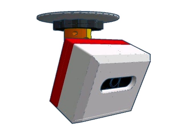
PiSec MKIII - Compact Edition by stmorgan
by Thingiverse
Last crawled date: 3 years ago
Wonder when people will get tired of me changing my designs.
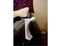
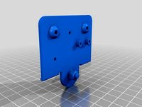
Printed out the body of MKII, and while the PiPlate, CamPlate and everything fit together fine with the POE adapter, pi, and camera installed, it was a little on the large side for my liking. So here's a compact edition. Went a different direction this time on the mount too.
Features:
► SMALLER.
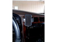
► Hidden network/power cable (POE)
► Looks better IMO.
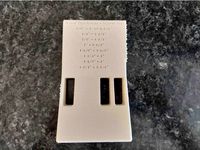
► Front begging for a logo.
► Entire body held together with four screws.
► Heat set inserts used in front case for durability.
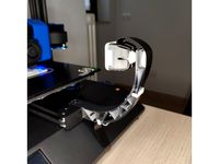
► Full 360° rotation and full 90° tilt. Able to look anywhere in a hemisphere.
► Only 9 11 printed parts for camera and mount.
► Built in light dam to cut reflective glare, accepts 20mm ODx1mm Section O-ring.
► Accepts 3mm acrylic lens in front case, has oval O-Ring groove that should accept a 65mm ODx2mm Section O-ring.
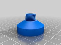
You'll need 4x 3mm screws that measure 72-73mm from tip to underside of head to hold the body together, and 2x 3mm nuts and screws for the ball clamp. You'll also need network cable crimping ability as the holes aren't big enough for an RJ-45 to pass through. The holes in the mounting ring will need drilling to your liking. The pockets for the heat sets are 5mm diameter as this seems to be best with my printer in PLA. There's a small .2mm staging pocket to help hold the insert steady while heating. A 73mm screw will just barely protrude below the insert, a 72mm should be just about flush with the bottom of it. There's 2mm or so of freebore below the insert to account for screw length. There should be about 8mm clear between the LEDs and the USB ports of the Pi to allow for some small heatsinks, these do get warm on my Makerfocus IR cam.
3/14/18:
► Added a jig to cut long 3mm screws down to proper length, simply insert and cut the end off flush with the jig using a hacksaw.
► Forgot to add the clips that hold the Pi onto the PiPlate. Make that 11 printed parts, but they're pretty inconsequential to print.
► Added a mounting ring with holes premade to fit a 4" round electrical box. (3-12" centers for 6-32 oval head machine screws.)
3/15/18:
► The POE splitter: https://www.ebay.com/itm/Active-PoE-Splitter-Power-Over-Ethernet-48V-to-5V-2-4A-Micro-USB-4-Raspberry-QH/292334777337?ssPageName=STRK%3AMEBIDX%3AIT&_trksid=p2057872.m2749.l2649
► The camera: http://a.co/5qq4F5M
► Screws I ordered, 80mm, need cutting down: https://www.ebay.com/itm/20X-M3-3-80mm-Round-Pan-Head-Phillips-Screws-304-Stainless-Steel-Machine-Screws/302237442873?hash=item465ec16339:m:mx6WLDv_UA4tFt-UxBnZHrQ
► Corrected O-Ring size. The proper size should be a 65mm OD x 2mm Section, not 1mm.
► Printed out the CamPlate and PiPlate, the two fit together fine, will assemble Pi and cam onto them this morning while the Front case half is printing and post pics.
3/16/18:
► Thinned the walls of the RearCase to 2mm, they were a little on the thick side. It matches the front now.
► Got distracted playing Minecraft while the front printed, don't have pics today. Everything seems to fit ok for now though.
► Looks like I had both O-rings wrong. The 65mm is 2mm section, the 20mm is 1mm section....
► I split the screw jig so it can be clamped (Lightly of course) in a vise and squeeze down to hold the screw.
► Rotated Clamp2 to what I think is the best orientation for printing. Supports in the ball socket would make it rougher than it should be.
3/17/18:
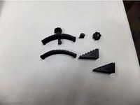
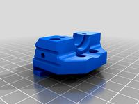
► Printed out Ball and Clamp1. These parts fit together beautifully with each other when pritned with 0.16mm layer height. Problems I ran into were the ball needed a raft under the supports since the whole thing basically sits on top of a support grid. The grid didn't have the surface area to stick down. The raft stuck to the feet a bit tight, that's my slicer settings though I imagine. Running a .2mm gap, I'll bump it to .28 or so. After seperation the feet seem a bit too large anyway. The clamp had 10mm hex pockets installed instead of 5.8mm that I've already determined to be a nice size for my 3mm nuts. I have no idea why I did that or how it got by me. Both of these parts printed fantastic as oriented. The ball needs a support grid and raft, but really it's only a few inches square, it's not that much plastic. The clamp printed standing vertically with supports over 50*, was one tiny little place that got a support pillar, and the inside of the holes, all came out fine except for my screwup with the pocket size.
► Uploaded corrected Ball and Clamp1 files. Shrunk the nut pockets in the clamp to a more reasonable size. Shrunk the diameter of the feet on the ball mount so they'll fit easier into the rear of the case.
3/20/18:
► Printed out nut, had to file ID to get a good fit onto Clamp1, increased bore size .3mm in STL, tight fit not needed here.
► Added 23mm screw jig for clamp screws. Regular 25mm would probably work fine too.
► Added Ball_TR file, intended for when you want to use 3mm threaded rod and nuts. This one has raised bosses for nuts, since the pockets on the normal version wouldn't allow them to be tightened.
► Added ScrewJig_TR file, used to trim threaded rod if you want to go this way. It should screw in until it bottoms out in the front case then assemble over rods and using Ball_TR it should be just enough protruding to use acorn nuts.
3/21/18:
► Modified Mounting rings, both versions have been changed to give 0.3mm more clearance around the boss on the bottom of the clamp. Was a little too tight to turn easily when I printed it out.
3/23/18:
► Modified MountRing-4RoundBox. Holes were too small, I was thinking normal mounting plate screws that are 6-32 but these are screws that go into the box itself, #8 or 4mm, so I made the holes 4.6mm with an 8mm large diameter on countersink. They should match most #8 or 4mm flat head screws well enough.
Printed out the body of MKII, and while the PiPlate, CamPlate and everything fit together fine with the POE adapter, pi, and camera installed, it was a little on the large side for my liking. So here's a compact edition. Went a different direction this time on the mount too.
Features:
► SMALLER.
► Hidden network/power cable (POE)
► Looks better IMO.
► Front begging for a logo.
► Entire body held together with four screws.
► Heat set inserts used in front case for durability.
► Full 360° rotation and full 90° tilt. Able to look anywhere in a hemisphere.
► Only 9 11 printed parts for camera and mount.
► Built in light dam to cut reflective glare, accepts 20mm ODx1mm Section O-ring.
► Accepts 3mm acrylic lens in front case, has oval O-Ring groove that should accept a 65mm ODx2mm Section O-ring.
You'll need 4x 3mm screws that measure 72-73mm from tip to underside of head to hold the body together, and 2x 3mm nuts and screws for the ball clamp. You'll also need network cable crimping ability as the holes aren't big enough for an RJ-45 to pass through. The holes in the mounting ring will need drilling to your liking. The pockets for the heat sets are 5mm diameter as this seems to be best with my printer in PLA. There's a small .2mm staging pocket to help hold the insert steady while heating. A 73mm screw will just barely protrude below the insert, a 72mm should be just about flush with the bottom of it. There's 2mm or so of freebore below the insert to account for screw length. There should be about 8mm clear between the LEDs and the USB ports of the Pi to allow for some small heatsinks, these do get warm on my Makerfocus IR cam.
3/14/18:
► Added a jig to cut long 3mm screws down to proper length, simply insert and cut the end off flush with the jig using a hacksaw.
► Forgot to add the clips that hold the Pi onto the PiPlate. Make that 11 printed parts, but they're pretty inconsequential to print.
► Added a mounting ring with holes premade to fit a 4" round electrical box. (3-12" centers for 6-32 oval head machine screws.)
3/15/18:
► The POE splitter: https://www.ebay.com/itm/Active-PoE-Splitter-Power-Over-Ethernet-48V-to-5V-2-4A-Micro-USB-4-Raspberry-QH/292334777337?ssPageName=STRK%3AMEBIDX%3AIT&_trksid=p2057872.m2749.l2649
► The camera: http://a.co/5qq4F5M
► Screws I ordered, 80mm, need cutting down: https://www.ebay.com/itm/20X-M3-3-80mm-Round-Pan-Head-Phillips-Screws-304-Stainless-Steel-Machine-Screws/302237442873?hash=item465ec16339:m:mx6WLDv_UA4tFt-UxBnZHrQ
► Corrected O-Ring size. The proper size should be a 65mm OD x 2mm Section, not 1mm.
► Printed out the CamPlate and PiPlate, the two fit together fine, will assemble Pi and cam onto them this morning while the Front case half is printing and post pics.
3/16/18:
► Thinned the walls of the RearCase to 2mm, they were a little on the thick side. It matches the front now.
► Got distracted playing Minecraft while the front printed, don't have pics today. Everything seems to fit ok for now though.
► Looks like I had both O-rings wrong. The 65mm is 2mm section, the 20mm is 1mm section....
► I split the screw jig so it can be clamped (Lightly of course) in a vise and squeeze down to hold the screw.
► Rotated Clamp2 to what I think is the best orientation for printing. Supports in the ball socket would make it rougher than it should be.
3/17/18:
► Printed out Ball and Clamp1. These parts fit together beautifully with each other when pritned with 0.16mm layer height. Problems I ran into were the ball needed a raft under the supports since the whole thing basically sits on top of a support grid. The grid didn't have the surface area to stick down. The raft stuck to the feet a bit tight, that's my slicer settings though I imagine. Running a .2mm gap, I'll bump it to .28 or so. After seperation the feet seem a bit too large anyway. The clamp had 10mm hex pockets installed instead of 5.8mm that I've already determined to be a nice size for my 3mm nuts. I have no idea why I did that or how it got by me. Both of these parts printed fantastic as oriented. The ball needs a support grid and raft, but really it's only a few inches square, it's not that much plastic. The clamp printed standing vertically with supports over 50*, was one tiny little place that got a support pillar, and the inside of the holes, all came out fine except for my screwup with the pocket size.
► Uploaded corrected Ball and Clamp1 files. Shrunk the nut pockets in the clamp to a more reasonable size. Shrunk the diameter of the feet on the ball mount so they'll fit easier into the rear of the case.
3/20/18:
► Printed out nut, had to file ID to get a good fit onto Clamp1, increased bore size .3mm in STL, tight fit not needed here.
► Added 23mm screw jig for clamp screws. Regular 25mm would probably work fine too.
► Added Ball_TR file, intended for when you want to use 3mm threaded rod and nuts. This one has raised bosses for nuts, since the pockets on the normal version wouldn't allow them to be tightened.
► Added ScrewJig_TR file, used to trim threaded rod if you want to go this way. It should screw in until it bottoms out in the front case then assemble over rods and using Ball_TR it should be just enough protruding to use acorn nuts.
3/21/18:
► Modified Mounting rings, both versions have been changed to give 0.3mm more clearance around the boss on the bottom of the clamp. Was a little too tight to turn easily when I printed it out.
3/23/18:
► Modified MountRing-4RoundBox. Holes were too small, I was thinking normal mounting plate screws that are 6-32 but these are screws that go into the box itself, #8 or 4mm, so I made the holes 4.6mm with an 8mm large diameter on countersink. They should match most #8 or 4mm flat head screws well enough.
Similar models
thingiverse
free
Raspberry Pi Camera front mount for Artillery Genius (ball nut) by pierm8
...commend printing the screw with x and y scaled 96% to fit the ball nut.
i used larryvand's clips for ribbon cable management.
thingiverse
free

Dremel Nut by Klave
... scaled 101% in the radial directions to make the fit slightly looser but 100% threaded on fine
lay it on its front face to print
grabcad
free

Ball Bearing Nut for TR8-2-D2 Screw
...i don't feel a backlash with it.
mf104zz ball bearing 3pcs.
pan head screw m4x12 3pcs.
hexagon nut m4 3pcs.
mounting holes m3
thingiverse
free

PiSec Cam MKII by stmorgan
...f camera.
3-12: added trimring-fixed, trimring_sealed-fixed. shrunk diameter of shoulder to 100.5mm to ease assembly/disassembly.
thingiverse
free
Pocket Hole Jig with guide lines by drumanick
...
clamp down pieces of wood to be connected, choose screw size based on wood thickness shown on top of jig.
screw wood together!
thingiverse
free
3rd Gen Toyota 4Runner Clock Bezel Phone Mount by dylan77
...sloppiest of machines, you'll probably be doing some post processing like cleaning the holes up a bit. scale x10 or 1000%...
3dwarehouse
free

Platform for Kreg Pocket Hole K4 Jig
...the jig. with this setup long boards can be squared up and clamped more securely in the jig for drilling. (drawn with sketchup 8)
thingiverse
free

M3 & M4 Test Calibration Part by iamjonlawrence
...arance hole, a tight clearance hole (with some resistance due to sag), and finally threaded directly into the part in third hole.
thingiverse
free
3/8 Inch (M6) Tripod Mount Phone Clamp Mount with 17.1mm Ball End by LumpyPrince
...ne and press fit a nut to mount it!
print at 100% infill for max stability around the ball joint.
fusion360 design file included!
thingiverse
free
Clamping system for MPCNC or similar by pavel569
...n reaching 7mm i pause and insert steel nut and continue printing.
nut 2 has hole through for inserting steel nut after printing.
Stmorgan
thingiverse
free
Garden hose to 1/4NPT adapter by stmorgan
...garden hose to 1/4npt adapter by stmorgan
thingiverse
need to back flush the block on the tractor. this should do it.
thingiverse
free

Honda Keychain Solid Back by stmorgan
...chain solid back by stmorgan
thingiverse
wanted a bit sturdier keychain so i filled in the hollow version with a 2mm thick back.
thingiverse
free

Flat top cap for desiccant box by stmorgan
...a slick lid to make everything easier to print by flipping it over and having it flat on the glass, so i chopped the letters off.
thingiverse
free

Big Black Bowden Bulkhead by stmorgan
...nt to print the regular nuts with a raft. i ran into problems with the overhang where it began building threads close to the bed.
thingiverse
free

Height Micrometer by stmorgan
...001"? just move one notch, loosen bit and lightly push it up from the underside until it contacts micrometer. retighten jig.
thingiverse
free

Blade disposal box for Stanley single edge razors by stmorgan
... stanley single edge razors by stmorgan
thingiverse
just a little box to keep your dull blades from poking out of the trash bag.
thingiverse
free
E3DNonVolcanoMount-enlarged nut pockets by stmorgan
...this and the 3mm nuts slip in much easier. i've however since swapped to a microswiss because i didn't like losing the y.
thingiverse
free
CR-10 Carriage minus wheels - TinkerCAD friendly by stmorgan
...ke this more tinkercad friendly. just slabbed them off. threads and standoffs are still there, x and z dimensions still the same.
thingiverse
free

CR-10 Pen holder by stmorgan
...ear the reduced diameter where the cap snaps on and trimmed the outside edge so it doesn't hang over the original x carriage.
thingiverse
free

Pi Camera mount by stmorgan
...al old pla, print the top standing vertically with supports, resist the urge to lay it flat, the hooks will break at layer lines.
Mkiii
3d_export
free

Austin-Healey 3000 MkIII
...austin-healey 3000 mkiii
3dexport
1965 austin-healey 3000 mkiii
3d_export
$49

1965 AustinHealey 3000 MkIII 3D Model
...tinhealey 3000 mkiii 3d model
3dexport
1965 austin-healey 3000 mkiii
1965 austinhealey 3000 mkiii 3d model dimary3 72450 3dexport
3d_export
$169
Churchill MKIII Kingforce 3D Model
... commonwealth gun weapon army us great britian england mki mkii mkiii
churchill mkiii kingforce 3d model panaristi 64276 3dexport
3d_export
$20

austin-healey 3000 mkiii
...s.<br>car textures:png - 2k resolution other available formats: obj, 3ds, fbx, stl, max. polycount: 38632 poly / 39975 tris
3d_export
$20

austin-healey 3000 mkiii
...s.<br>car textures:png - 2k resolution other available formats: obj, 3ds, fbx, stl, max. polycount: 38632 poly / 39975 tris
cg_studio
$109

Aston Martin DB MKIII (1957-1959)3d model
...io
.obj .max .fbx - aston martin db mkiii (1957-1959) 3d model, royalty free license available, instant download after purchase.
3d_export
$149

M4 Sherman MKIII Early Production 3D Model
...zer ww2
m4 sherman mkiii early production 3d model download .c4d .max .obj .fbx .ma .lwo .3ds .3dm .stl panaristi 109506 3dexport
3d_export
$191
MartinBakerMk10 3D Model
...mkix harrier jet aircraft escape parachute cockpit military modern mkiii martinbakermk10 3d model mkiii 19586...
3d_export
$160

Nieuport 11 3D Model
...great war aircraft french biplane le-rhone bebe lafayette escadrille mkiii nieuport 11 3d model mkiii 19569...
3d_export
$190

Sherman M4A1 tank 3D Model
...american armor armour tracked d-day british wwii ww2 m4 mkiii sherman m4a1 tank 3d model mkiii 19566...
Compact
3d_export
$5

compact freezer
...compact freezer
3dexport
the compact freezer is product about refrigeration machine
3d_ocean
$8
Compact Cassette
...
80s album analog audio cartridge cassette compact digital electronics lp mp3 music play record sound tape vinyl
compact cassette
design_connected
$20
Eames Compact
...eames compact
designconnected
herman miller eames compact computer generated 3d model. designed by eames, charles.
3d_ocean
$2

Compact Disc
...compact disc
3docean
album audio cd compact disc dvd laser disc movie music
a cd
3d_export
$10

land compacter
...land compacter
3dexport
turbosquid
$1
Compact knife
...quid
royalty free 3d model compact knife for download as obj on turbosquid: 3d models for games, architecture, videos. (1557900)
3d_export
$12
compact rotary broach
...compact rotary broach
3dexport
compact tool for drilling hexagonal holes in lathes!
turbosquid
free

Lada Compact
... 3d model lada compact for download as max, max, max, and fbx on turbosquid: 3d models for games, architecture, videos. (1623122)
turbosquid
$59

Compact Truck
... available on turbo squid, the world's leading provider of digital 3d models for visualization, films, television, and games.
turbosquid
$50
Compact kitchen
... available on turbo squid, the world's leading provider of digital 3d models for visualization, films, television, and games.
Edition
turbosquid
$33
Natuzzi Editions
... available on turbo squid, the world's leading provider of digital 3d models for visualization, films, television, and games.
turbosquid
$29
Guitar_MJ-Edition
... available on turbo squid, the world's leading provider of digital 3d models for visualization, films, television, and games.
turbosquid
$20
Editable Fountain
... available on turbo squid, the world's leading provider of digital 3d models for visualization, films, television, and games.
3ddd
$1

Kueco Edition Palais
...kueco edition palais
3ddd
keuco
зеркальный шкаф kueco edition palais
design_connected
$16

369 Classic Edition
...369 classic edition
designconnected
walter knoll 369 classic edition computer generated 3d model.
3ddd
$1
Martz Edition
...martz edition
3ddd
martzedition
http://www.martzedition.com/a-500-3
3ddd
$1
Martz Edition
...martz edition
3ddd
martzedition
http://www.martzedition.com/b-400-3
design_connected
$25
Chester - Limited Edition
...nnected
established & sons chester - limited edition computer generated 3d model. designed by future systems, amanda levete.
3ddd
$1

KROKEN LIMITED EDITION
...d
rochebobois
autumn/winter collections 2012 rochebobois paris
kroken limited edition armchairhttp://m.roche-bobois.com
3ddd
$1
stilwerk limited edition
...stilwerk limited edition
3ddd
3000х1200х750