Thingiverse
PiClop 3D Scanner by bruckj
by Thingiverse
Last crawled date: 3 years ago
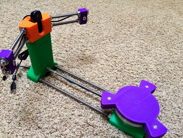
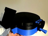
This is a modification of bqLabs CiClop 3D Scanner. I have changed it to accommodate a Raspberry Pi in place of the Arduino. I have not completed the electrical circuit or software.
Sketchup files are included.
Laser Mount
relocated the nut so that it inserts from inside of the laser mounting hole this provides more material around the nut and makes it easier to remove if needed
use an M3 bolt and nut
Turn Table Base
removed the M8 nut traps, the original design did not allow for easy adjustment of the M8 bolt lengths, I have changed the design so that you can adjust this easier, I did recess the nuts on one side - you will need a socket for these
added clips that bolt (25mm M5 hex bolts and nuts) in place to hold the bearing, these have nut traps on the underside acccessed from where the motor mounts
removed foot locators
removed all the extra supports (they are not needed for printing), the only supports are for the motor shaft and bolts and the bearing mount bolts, these are easily cleaned with a drillbit and knife
Table Plate
had to increase some of the dimensions slightly to accomodate the bearing better (probably due to my printer capabilities)
increased the volume around the shaft coupling socket, I found that the original design was prone to layer separation when the part was twisted
I removed the supports for the bearing clips and print them on their side (no supports needed)
there are supports in the bolt holes that will need to be cleaned out with a drillbit
use three button head M6 25mm bolts and nuts to mount
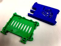
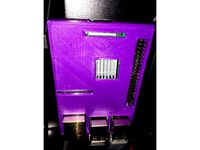
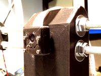
Case
modified to fit a Raspberry Pi
the case is split into two pieces so that they can be printed on smaller beds
the pieces are bolted together, use two M5 20mm hex bolts and nuts to attach the top to the base (there are nut traps accessed from the inside of the top housing)
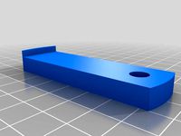
the Raspberry Pi is held in place with two printed spring clips
I removed all the extra supports from the original, print the case pieces face down, no addition supports should be needed
the lid should be printed on end, I use an extra wide brim to give support against bed motion
four 12mm M3 bolts and nuts to mount the cover, the nuts slide into a but trap in the main housing (be sure to clear the holes of supports first using a drillbit)
Shaft Coupling
used the original as-is
Sketchup files are included.
Laser Mount
relocated the nut so that it inserts from inside of the laser mounting hole this provides more material around the nut and makes it easier to remove if needed
use an M3 bolt and nut
Turn Table Base
removed the M8 nut traps, the original design did not allow for easy adjustment of the M8 bolt lengths, I have changed the design so that you can adjust this easier, I did recess the nuts on one side - you will need a socket for these
added clips that bolt (25mm M5 hex bolts and nuts) in place to hold the bearing, these have nut traps on the underside acccessed from where the motor mounts
removed foot locators
removed all the extra supports (they are not needed for printing), the only supports are for the motor shaft and bolts and the bearing mount bolts, these are easily cleaned with a drillbit and knife
Table Plate
had to increase some of the dimensions slightly to accomodate the bearing better (probably due to my printer capabilities)
increased the volume around the shaft coupling socket, I found that the original design was prone to layer separation when the part was twisted
I removed the supports for the bearing clips and print them on their side (no supports needed)
there are supports in the bolt holes that will need to be cleaned out with a drillbit
use three button head M6 25mm bolts and nuts to mount
Case
modified to fit a Raspberry Pi
the case is split into two pieces so that they can be printed on smaller beds
the pieces are bolted together, use two M5 20mm hex bolts and nuts to attach the top to the base (there are nut traps accessed from the inside of the top housing)
the Raspberry Pi is held in place with two printed spring clips
I removed all the extra supports from the original, print the case pieces face down, no addition supports should be needed
the lid should be printed on end, I use an extra wide brim to give support against bed motion
four 12mm M3 bolts and nuts to mount the cover, the nuts slide into a but trap in the main housing (be sure to clear the holes of supports first using a drillbit)
Shaft Coupling
used the original as-is
Similar models
thingiverse
free

LulzBot Taz 6 Raspberry Pi Mounting Clip by case2001
...gned for the lid of the canakit case to be in place. i mounted mine above the extruder on control box side. no supports needed.
thingiverse
free

TV Hook for Raspberry PI Case by Mr_Alicates
... tv using an (up to) m6 bolt.
you will also need the appropiate bolt for your tv hole and a few nuts to lock everything in place.
thingiverse
free

Raspberry Pi Mount for Anet A6 by wenzej
... since i dont know what kind of raspberry case you are using or how it is mounted you will have to drill your own holes for that.
thingiverse
free

Raspberry Pi Ethernet Mount by wihami
...port of the pi. the rod used to attach the mounting pieces was 5/16" aluminum rod and the bolt at the top is an m3 x 10 mm.
thingiverse
free

Frame for Raspberry Pi by builtbybogus
...ottom. you can do that, too.
attention: this case works only with the raspberry pi b (the one with holes in the pcb). have fun!
thingiverse
free

Raspberry Pi Case Bolted by kasey
... "raspberry pi case" thingiverse.com/thing:30572 designed by redpeppr.
i have added support for four m3 bolts with nut.
thingiverse
free

Raspberry Pi B+ Mount Plate by Ecogeeco
...ertical. i may add clips later.
i printed this at 50% infill to make the screw holes tough enough to not crack when tightened.
thingiverse
free
OctoPi Case V-Slot Mount by aaronroma
...t, print two of the m3 t-nuts. you will then need 2 m3 nuts to press fit into the t-nuts. you will also need 2 m3 x 6mm bolts.
thingiverse
free

Raspberry Pi Zero W / Makerbot Replicator 2/2X Corner Camera Case by tmclucas
...longer bolt and nut.
m3 bolt and nut
for case back print bolt hole side down for back piece. remove hole support after printing.
thingiverse
free
Wanhao i3 Clip on Raspberry Pi Octoprint Case with heat sink hole by mkanoap
...ith the raspberry pi.
print this instead of the "body2.stl" piece along with the lower body and clip from the original.
Piclop
thingiverse
free

Diffuser for PiClop Light by FaanP
...ghts here: http://www.thingiverse.com/thing:799671
you can find the piclop scanner here:http://www.thingiverse.com/thing:754003
thingiverse
free
PiClop small addons by benignogobbo
...i was asked to add their stls, so here they are...
the disk holder is itself a remake of http://www.thingiverse.com/thing:806059
thingiverse
free
Piclop camera holder by owens
...with m2-20 screws and adjusted to aim it at the turntable.
the license is set to cc-by-nc in keeping with vger's original.
thingiverse
free

Piclop Camera Bezel by cd0156
...nly different part.
i printed this square side down with the eye looking up. i used support touching buildplate only with 15deg..
thingiverse
free

Spotlights for PiClop Scanner by FaanP
... still need to do proper test but thus far it seems fine.
update: diffusers for lights: http://www.thingiverse.com/thing:810178
thingiverse
free

Raised smaller scanner plate base for Ciclop / Piclop by ephestione
...y most printers, with less plastic, and has recessed slots for m6 nuts, plus a small hole in the center to help with calibration.
thingiverse
free

PiClop Laser Scanner by FaanP
...the piclop now available: http://www.thingiverse.com/thing:799671
diffusers for lights: http://www.thingiverse.com/thing:810178
thingiverse
free

Piclop fixed laser holder by iwant3d
...ify the values in freelss but they work pretty well and reliably.
this is also symmetrical so the one part works on both sides.
thingiverse
free

PiClop Laser Scanner with IR cam & adjustable lens by GabrieleDaghetta
...a 10mm light and rigid foam board panel.
more info on https://store.open-electronics.org/index.php?_route_=electronics_3d_scanner
thingiverse
free
Piclop camera and laser mounts by owens
...sign now because a few people have asked for the parts, but if you print them now be aware that they may not be fully functional.
Bruckj
thingiverse
free

Bandsaw Throat Plate by bruckj
...this is a throat plate for my 12” delta model 28-190 bandsaw.
the sketchup file is included and i used slic3r to generate g-code.
thingiverse
free

Bandsaw Fence by bruckj
...he bandsaw table. the levers rock open to release the clamp.
the sketchup file is included.
slic3r was used to generate g-code.
thingiverse
free

NUC under desk mount by bruckj
...l nuc under a desk. uses #6 screws. dimensioned to leave the feet on the nuc and compress them slightly for a snug, secure fit.
thingiverse
free
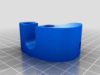
Filament Guide by bruckj
...ome longer ones.
i am using slic3r to generate g-code.
sketchup files are included.
2016-01-23 update: cleaned up sketchup file.
thingiverse
free

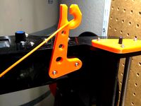
Nerf Grappling Hook by bruckj
...03-10
updated the stl to remove the supports as i think it was messing up g-code generation
recommend you use a raft for printing
thingiverse
free
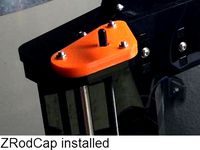
Z Rod Caps by bruckj
...s recesses for the zrod and z-axis screw bearings and insets for the mounting nuts.
2016-01-23 update: cleaned up sketchup file.
thingiverse
free

G3D Cable Bracket by bruckj
...3d.) an optional four cable solution is also provided along with the sketchup file
2016-01-23 update: cleaned up sketchup file.
thingiverse
free

Bandsaw Miter Gage by bruckj
.../-22.5°, and 0°.
i am using slic3r to generate g-code.
sketchup files are included.
2016-01-24 update: cleaned up sketchup file.
thingiverse
free
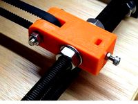
Y-Axis Tensioner by bruckj
...ws the embedded nut to be pushed out (removed)
an inset for the bearing bolt nut
2016-01-24 update: cleaned up sketchup file.
thingiverse
free

Spur keychain 1:1.75 by bruckj
...picture) these were designed as a tight fit for my printer and slic3r - adjustment may be needed.
the sketchup file is included.
Scanner
archibase_planet
free

Scanner
...chibase planet
scanner pc equipment image scanner
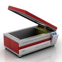
scanner cyrel 2000 eclf - 3d model (*.gsm+*.3ds) for interior 3d visualization.
archibase_planet
free
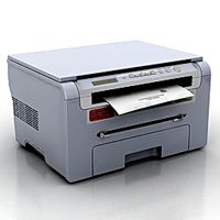
Scanner
...scanner
archibase planet
scanner pc equipment
scanner samsung scx-4200 n030211 - 3d model (*.3ds) for interior 3d visualization.
3d_ocean
$6
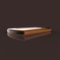
Scanner
...
3d models computer electronics peripheral / part
scanner computer 3d models. 3d model of computer scanner to use in your scenes.
archibase_planet
free
Scanner
...scanner
archibase planet
scanner
scaner - 3d model (*.gsm+*.3ds) for interior 3d visualization.
turbosquid
$6

scanner
...id
royalty free 3d model scanner for download as max and obj on turbosquid: 3d models for games, architecture, videos. (1518492)
3d_export
$40
3d scanner
...3d scanner
3dexport
3d scanner please rate
3d_export
$10

scanner bot
...scanner bot
3dexport
cool scanner bot who scans for fixing things...
archive3d
free
Scanner 3D Model
...scanner
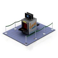
scanner objects airport n240616 - 3d model (*.gsm+*.3ds) for interior 3d visualization.
3d_ocean
$6
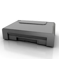
Scanner Computer
...r electronics peripheral / part printer
3d model of computer scanner to use in your scenes. scanner computer peripheral 3d models
archive3d
free
Scanner 3D Model
...t image scanner
scanner cyrel 2000 eclf - 3d model (*.gsm+*.3ds) for interior 3d visualization.