GrabCAD
Peristaltic Pump
by GrabCAD
Last crawled date: 1 year, 11 months ago
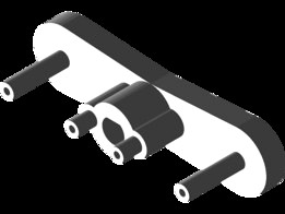
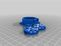
Peristaltic Pumps move liquid by pushing rollers along a segment of silicone or rubber tubing, which propels liquid through the tube. This peristaltic pump is meant to be 3D printed. All of the files named "Peristaltic Pump Part..." can be printed.
Parts that need to be obtained separately are: a silicone tube (ID: 4mm OD: 6mm), an electric motor (Standard Spur Gear Motors on ServoCity), four 3 cm M5 bolts, four M5 nuts, four bearings with an outer diameter of 1.3 cm and an inner diameter of 0.4 cm.
To assemble, take "Peristaltic Pump Part 1" and put two bearings on both of the axles furthest from the center. There should be two bearings per axle. Next, take "Peristaltic Pump Part 2" and affix it to the top of "Peristaltic Pump Part 1," right on top of the bearings. "Peristaltic Pump Part 2" has a small indentation at its center; when attaching to "Peristaltic Pump Part 1," make sure it's facing "Peristaltic Pump Part 1." Next, take the electric motor and set it into the large cylindrical cavity on the back of "Peristaltic Pump Part 3." Make sure that the electric motor's axle fits through the small hole on "Peristaltic Pump Part 3" and that the electric motor fits flush against the back of "Peristaltic Pump Part 3." Next, fit the silicone tubing in a U shape inside of the front side of "Peristaltic Pump Part 3" so that the two ends of the silicone tube fit through the two trenches on the front side of "Peristaltic Pump Part 3." If you're unsure how to fit the silicone tube in the pump, take a look at the Peristaltic Pump.step file; it has the tube included. Once the tube is in, fit the Peristaltic Pump Parts 1 and 2 assembly onto the axle of the electric motor. Make sure that "Peristaltic Pump Part 1" (which has a hole in its center) is the side that fits directly onto the electric motors axle. Also, make sure that the bearings are making complete contact with the silicone tube. Next, fit "Peristaltic Pump Part 4" over the silicone tube and two trenches on "Peristaltic Pump Part 4." Next, fit two M5 bolts through the two tops of "Peristaltic Pump Part 3" and fit two M5 nuts into the corresponding nut insets on the bottom of "Peristaltic Pump Part 3." Finally, fasten the M5 bolts into the nuts, firmly securing the "Peristaltic Pump Part 3" onto "Peristaltic Pump Part 4." The peristaltic pump is now functional.
Optionally, you can cut a 7.5 cm by 82 cm piece of 0.15 cm polycarbonate or acrylic to affix on top of the case as a lid. I haven't made a cutting or drilling guide for the lid yet. To assemble, remove the M5 bolts and fit all four M5 bolts into the top to the lid, through "Peristaltic Pump Part 3," and secure with bolts on the back of "Peristaltic Pump Part 3." Now your peristaltic pump has a cool clear lid and some cool looking metal bolts. nice.
Similar models
thingiverse
free

Peristaltic pump by nicoruy
...4" thread, 1" length screww and nuts (bearings fixture)
1x 1/4" thread, 1.5" length screw and nut (main axis)
thingiverse
free

NEMA-17 Peristaltic Pump by CopabX
...s
two m3x12mm screws
four 8mm od, 3mm id bearings
one nema-17 stepper motor (at least 4 kg/cm)
2mm od, 1mm id soft silicon tubing
thingiverse
free

Generic Peristaltic Pump by sergek
...ngs
2pcs 8x22x7mm bearings
8mm shaft (i've used aluminium tube)
4pcs 20mm m4 screws with nuts
4pcs 45mm m3 screws with nuts
thingiverse
free

Yet another peristaltic dosing pump by ppet36
...e of diameter 4/6 mm (int/ext); servo has enough torgue to handle it.
pump in action: https://www.youtube.com/watch?v=piet5409c1g
thingiverse
free

Peristaltic pump for NEMA17 motor by Lorenzo1995
...mple peristaltic pump for nema 17 stepper motor
needed parts:
2 m3x20 screw
3 ball bearing 686zz
silicon pipe id 2/3mm od 5/6mm
grabcad
free

NEMA-17 peristaltic pump low volume tube 4x2
...altic pump
properties:
- bearing: 623zz (id 3mm, od 10mm, thinkess: 4mm)
- silicone tube (id 2mm, od 4mm)
- m3 countersunk bolts
thingiverse
free

NEMA-17 Peristaltic Pump V2 by CopabX
...e.com/products/copabx/nema-17-peristaltic-pump-kit/
build instructionshttp://www.instructables.com/id/nema-17-peristaltic-pump/
thingiverse
free
Peristaltic pump for 5V DC stepper motor, small volume
...7mm. diameter-inner=4.58mm, height= 4.95mm)
1 stator
1 rotor(2 parts)
1 cover
4mm silicone tube with 3mm hole inside, any length.
thingiverse
free

Micro Peristaltic Pump by neoaikon
...the best choice.
included is also a 2.25" version for use with 1/4" tubing. this version is suitable for .4mm nozzles.
thingiverse
free

Nema17 peristaltic pump by Cristian2281
...mp and pin. rollers to be printed if not using mr105zz bearings.
this is still a work in progress and should be treated as such.
Peristaltic
thingiverse
free

Peristaltic pump by Daniele_Dondi
...peristaltic pump by daniele_dondi
thingiverse
precise peristaltic pump
thingiverse
free

Peristaltic pump by MarcoKl
...ng resolution is not mandatory.
you should put a rubbery tape inside the frame where the tube is placed to take care of the tube.
thingiverse
free

Peristaltic Pump With IKEA Motor (4 - 4.5l/min!) by PattysLab
...of startup current!! (3-6a startup)
instructions:
watch the videos to understand how you make this to avoid unessisary questions.
thingiverse
free

Hand Sanitizer Dispenser by dnkorte
...by dnkorte thingiverse hand sanitizer (or soap) dispenser uses peristaltic pump to dispense fluid when adafruit vcnl optical proximity...
thingiverse
free

RC Fuel peristaltic pump by mceze
...ping for the pump case
3 pcs m2.5 x 10mm and matching nylon nuts for the pump rotor
3 pcs m3x 6mm for holding the motor in place
thingiverse
free

Kamoer heavy duty peristaltic pump by Beefrox
...i'll design a proper mount and stand offs for the board.
the tabs on the back case are designed to fit an m4 threaded insert.
thingiverse
free

Enclosure for Honlite dosing pump by inventmarine
...is also a hole for a 12v dc jack. https://www.ebay.com.au/itm/peristalticdosing-pump-deliver-500ml-min-450ml-min-pharmed-tygon-tube-dc12v-24v/162276139921?sspagename=strk%3amebidx%3ait&_trksid=p2057872.m2749.l2649 ...
thingiverse
free

Peristaltic pump by JKUgalde
...ingiverse
instructions at my github https://github.com/jkugalde/3d-printed-peristaltic-pump
tested with glycerine.
for a nema17.
thingiverse
free

Peristaltic Pump Cover Adapter by 2JZ_Tacupra
...ikcnneruaak9realw_wcb:g:s&s_kwcid=al!2966!3!264955916363!!!g!630077959432!&gucid=n:n:ps:paid:ggl:csm-2295:q87mp9:20500731
thingiverse
free

Peristaltic Pump Dual Hose Retainer by 2JZ_Tacupra
...peristaltic pump dual hose retainer by 2jz_tacupra
thingiverse
hose retainer for dual hose peristaltic pump
Pump
3d_export
$8

S revit 1 3D Model
...s revit 1 3d model 3dexport boot women girl pump shoe leater heel tassel brown baked white high detail...
3d_export
$8

Mesh boot 3non rigged 3D Model
...boot 3non rigged 3d model 3dexport boot women girl pump shoe leater heel tassel brown baked white high detail...
3d_ocean
$25

GardenHouse2
...garden house home house ivy low poly old water pump place single house small apartment spathiphyllum low poly garden...
3d_ocean
$19

Oil Pump (Pumpjack)
...od choice for arhitecture vizualisations, video games and etc. possible in: c4d r11, c4d r15, max 2010, dae 1.4, fbx 6, 3ds, obj.
3d_export
$20
Gas Pump Gilmore 3D Model
... antique pipe meter fuel 3d
gas pump gilmore 3d model download .c4d .max .obj .fbx .ma .lwo .3ds .3dm .stl joshim 106934 3dexport
3d_export
$99

Remington Model 870 3D Model
...model 3dexport remington model 870 combat shotgun shot gun pump semi automatic us american weapon army remington model 870...
3d_export
$20
Gas Pump Musgo 3D Model
... gulf antique pipe meter fuel
gas pump musgo 3d model download .c4d .max .obj .fbx .ma .lwo .3ds .3dm .stl joshim 106937 3dexport
3ddd
$1

Декоративный набор Decor
..., фоторамка , рама , prisma , туфли , pump , коробка , стена , молдинг декоративный...
3ddd
$1
Pottery Barn
...barn http://www.potterybarn.com/products/holden-glass-metal-bath-accessories/?cm_src=autocatrel toothbrush holder: 3.5" diameter, 4.5" high soap pump 3.5" diameter, 6.75" high small canister: 4.5" diameter, 4.5"...
archive3d
free
Pump 3D Model
... model
archive3d
pump water pump
pump 1 - 3d model (*.gsm+*.3ds) for interior 3d visualization.