Thingiverse
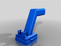
Parkside X20V battery adapter - Mini Power Supply
by Thingiverse
Last crawled date: 4 years, 2 months ago
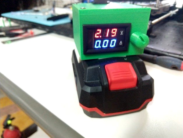
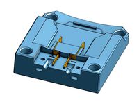
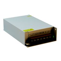
Starting from nullusr's design, I used the original battery rail piece, and created a mini power supply using a DC-DC buck converter (LM2596) and a Voltmeter-Ampmeter display (YB27VA ), fitting everything inside a relatively small box. The output comes from 2 banana plug sockets on the back, and it can be switched on/off with a pushbutton on the top.
I also added a fitting potentiometer knob :)
Connections:
+20V from battery to DC-DC IN+ and YB27VA supply+ (the thin red wire)
0V from battery to DC-DC IN- and YB27VA supply- (the thin black wire)
DCDC OUT+ to YB27VA PW+ (thick red wire) and one leg of the pushbutton
DCDC OUT- to YB27VA COM (thick black wire)
YB27VA IN+ (Thick yellow wire) to black banana plug socket
The remaining leg of the pushbutton to the red banana plug socket
I removed the original 10kOhms trimmer in the switching DC-DC converter, and put a sturdier potentiometer I had spare, which could fit in the power supply box. I had to also add spacers and a block to keep it in place, since it did not have a nut to block it. Depending on the potentiometer you have, you might just need a washer and a nut to keep it in place.
with a 10kOhms potentiometer, output voltage range is 1.2-19.8V with a fully charged battery. Buck converter is rated up to 3Amps so it should be fine. The only downside is that, with these electronics, it is not possible to limit the output current.
BOM:
4x M4x16 bolts + 4x M4 nuts to fix rail and box together (or 3x M4x16 + 1x M4x20 if the potentiometer block is mounted)
4x M3x10 bolts (to screw the lid to the box)
1x YB27VA display ( https://www.amazon.com/BenchTech-BT-YB27VA-2-color-Voltmeter-Red-Blue/dp/B00ML6VVUE )
1x LM2596 DC-DC converter (https://www.amazon.com/LM2596-Converter-3-0-40V-1-5-35V-Supply/dp/B01GJ0SC2C )
1x 10kOhms potentiometer (like this one: https://www.amazon.com/Uxcell-a15011600ux0235-Linear-Rotary-Potentiometer/dp/B01DKCUVMQ/ref=sr_1_4?keywords=10k+potentiometer&qid=1572095546&sr=8-4 )
2x banana plugs (red and black)
2x banana plug sockets (e.g. like this: ( https://www.amazon.com/Hilitchi-Binding-Terminals-Banana-Arduino/dp/B07PFMD1N2 )
1x self locking pushbutton switch to enable disable the output sockets
some female fastons for the pushbutton
some red and black awg14 (or similar) wires. I used about 30 cm each.
some awg 22 wire for the 3 pins of the potentiometer (about 7-8 cm each)
some soldering skills :)
EDIT: added original adapter battery rail
Print Settings
Printer:
Anet A8
Supports:
Not required
Resolution:
0.2
0.32 for the lid
Infill:
20
Similar models
thingiverse
free

Yet another HP DPS 600B Terminal by fakeputz
...giverse
hp dps 600pb terminal
fits for:
4x 4mm terminal banana plug socket
1x mini digital voltmeter
1x trimmer potentiometer
thingiverse
free

LM2596 Power Supply by Blender1971
...onnector 2.1/5.5mm.
left set of banana sockets is connected to input and right set of sockets is connected to power supply output
thingiverse
free

PowerLAB, Another ATX power supply for Lab
...g detailled
add commercial reference for parts
add option for voltmeter on 3.3v, 5v and 12v
add fuse for dc converter protection.
thingiverse
free
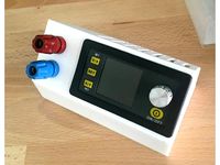
DSP5005 power supply case by Mattes34
...the dps5005 power supply.
1x hirschmann banana socket black
1x hirschmann banana socket red
1x dc jack 5.5x2.5mm with a 11mm hole
thingiverse
free

DROK LM2596 Analog DC-DC converter by malaiwah
... to 24v to 12v to 5v adjustable 5-40v to 1.25-37v step down variable volt power supply stabilizers car battery red led voltmeter)
thingiverse
free
Variable power supply by Giammy_hsq_99
...ring in the back cover, there is a housing for two plastic clamps which have the task of keeping the wires firm in case of draft.
thingiverse
free
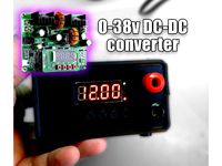
D3806 DC-DC Buck Boost Converter 38v - Power Supply - Box by paul0
...able
female socket
3d printing
1x front panel
1x back panel
1x top
1x bottom
4x foot
4x button
note: you need to glue the buttons
thingiverse
free

Case for RD DPS5005 DC-DC step down module (laboratory mini power supply) by Egorich
...l4a57bw
4) banana plugs couple terminal: https://www.amazon.com/highrock-terminal-binding-amplifier-copper/dp/b00d6aicr4
5) wires
thingiverse
free

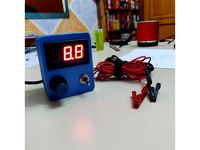
Banana plug expansion box by manchagnu
...azon.com/dgzzi-regular-terminal-amplifier-connectors/dp/b07pxknssc
voltmeter/ammeter:https://www.amazon.com/gp/product/b06xr2xknt
grabcad
free

LM2596 DCDC Converter
...is sort of item commonly found on amazon.
https://www.amazon.com/adjustable-converter-1-5-35v-efficiency-regulator/dp/b07c2qf1t1
X20V
thingiverse
free

adattatore parkside x20V a powerbank by SamueleLg
...sfruttare le batterie parkside x20v team come un powerbank utilizzando un comunissimo adattatore da accendi sigari per auto a usb
thingiverse
free
Parkside X20V Arbeitslicht by kay_1971
...es arbeitslichtes, ausgelegt für
https://www.wish.com/product/5df9c24ba0f3b408d6cb620c
und einen standard kippschalter (28*12mm)
thingiverse
free

Parkside PABH adapter x20v team by diegomax
...parkside pabh adapter x20v team by diegomax
thingiverse
adapter for parkside pbah 18 li a1
thingiverse
free

Dual parkside x20v battery adapter by JernejL
...es.
make your own 4ah battery, or even crazyer: combine 2 4ah batteries into one 8ah battery.
posted with permission from glol.
thingiverse
free

Lidl Parkside X20V Team Powerbank USB Adapter by Knuspel
...board
stackable design so that each part is easy to print. the screws are directly screwed into the material. do not overtighten.
thingiverse
free

Parkside x20v battery adapter for 12v lighter socket by GLoL
... 12v !!!
one piece print !!
the drawing was optimize to be printed upwards,no supports needed
(thingverse cant generate previews)
thingiverse
free
Lidl Parkside X20V adapter by misil
...e na kontaktech.
https://cad.onshape.com/documents/d55b391241c770a5e72bf94a/w/43fd5f1289571e1c07fb2d0d/e/631db234c99c9881fcc640d6
thingiverse
free

Parkside X20V to Parkside PDSSA 18 A1 Fixed by Alex2244
... print i need to sanding a lot on the 18v battery part. other than that, the model is very good and a big thanks to andrzejdevil!
thingiverse
free

Parkside X20V Team Charger Wall Mount by jaaanik
...the recommended orientation of the elements when printing.
walls thickness 1.6 mm (4 shells). layer height 0.2 mm. infill 25-30%.
thingiverse
free

Lidl Parkside X20V Team Battery Adapter by Knuspel
... m2 screws (~8mm length) to mount the top plate onto the bottom plate. i used hot glue to hold the cable shoes in place properly.
Parkside
thingiverse
free

PARKSIDE ACCU
...parkside accu
thingiverse
parkside accu
thingiverse
free

Parkside hammer grip
...parkside hammer grip
thingiverse
parkside hammer grip
thingiverse
free
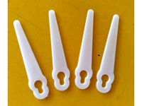
Parkside blade by cecnet
...parkside blade by cecnet
thingiverse
parkside blade.
abs
thingiverse
free

Parkside 12 A1
...parkside 12 a1
thingiverse
parkside 12vhalterung, park 12 a1
thingiverse
free

Parkside 20V mount
...parkside 20v mount
thingiverse
parkside 20v mount, for paralell to wall mount
thingiverse
free

Parkside to SN50T6 by dejx
...parkside to sn50t6 by dejx
thingiverse
parkside vacuum hose to sn50t6 dust cyclone separator adapter
thingiverse
free

Battery PARKSIDE
...battery parkside
thingiverse
housing for lion accu.
thingiverse
free

Parkside organizer separator by hugo_sa
...parkside organizer separator by hugo_sa
thingiverse
separator for parkside organizer.
thingiverse
free

Parkside PFBS12A1 Halter by JMDesigns
...parkside pfbs12a1 halter by jmdesigns
thingiverse
parkside pfbs12a1 halter
thingiverse
free

Parkside multitool wrench by lucibrandus
...parkside multitool wrench by lucibrandus
thingiverse
parkside multitool wrench
Supply
turbosquid
$1

supplies
... available on turbo squid, the world's leading provider of digital 3d models for visualization, films, television, and games.
3d_export
$5

black supply
...black supply
3dexport
black supply size: 57.9 x 29.2 x 34 sm
turbosquid
$20

Office Supplies
...lty free 3d model office supplies for download as max and obj on turbosquid: 3d models for games, architecture, videos. (1273636)
3d_export
free

office supplies
...office supplies
3dexport
turbosquid
$8

Supply Drop
...e 3d model supply drop for download as fbx, obj, dae, and stl on turbosquid: 3d models for games, architecture, videos. (1663721)
turbosquid
$75

Supply Helicopter
... available on turbo squid, the world's leading provider of digital 3d models for visualization, films, television, and games.
turbosquid
$65
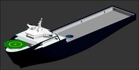
Supply Ship
... available on turbo squid, the world's leading provider of digital 3d models for visualization, films, television, and games.
turbosquid
$29

Village Supplies
... available on turbo squid, the world's leading provider of digital 3d models for visualization, films, television, and games.
turbosquid
$19

Power Supply
... available on turbo squid, the world's leading provider of digital 3d models for visualization, films, television, and games.
turbosquid
$5

school supplies
... available on turbo squid, the world's leading provider of digital 3d models for visualization, films, television, and games.
Battery
3d_ocean
$2
Battery
...battery
3docean
battery electronic
a high quality battery .
3d_export
free

battery
...battery
3dexport
battery
3d_ocean
$5
Battery
...battery
3docean
battery electronics
a classic 6 v battery, high poly with materials
3d_ocean
$3
Batteries
...batteries 3docean aa aaa batteries battery d electronics energy materials power subdivision uv unwrapped aa,...
3d_export
$19
Lead-acid battery storage battery lithium battery
...ttery storage battery lithium battery
3dexport
1.lead-acid battery storage battery lithium battery 2.files include 3dmax obj fbx
3d_ocean
$7
Battery Model
...battery model
3docean
big battery car battery vehicle battery
car battery, big battery, vehicle battery.
3ddd
free
battery energier
...battery energier
3ddd
battery energier , батарейка
battery energier
turbosquid
free
battery
...battery
turbosquid
free 3d model battery for download as obj on turbosquid: 3d models for games, architecture, videos. (1151676)
3d_ocean
$1
Battery Model
...lack minus plus white yellow
this is battery model is about 1000 triangles. turntable preview is smoothed version of the battery.
3d_export
$10
battery 18650
...battery 18650
3dexport
battery 18650
Mini
turbosquid
$10
Mini Mini Luceplan
...
royalty free 3d model mini mini luceplan for download as max on turbosquid: 3d models for games, architecture, videos. (1227359)
3d_ocean
$39

Mini Cooper
...mini cooper
3docean
cabrioler cooper mini
mini cooper cabrioler
3d_export
$30

Mini lathe
...mini lathe
3dexport
mini lathe
3d_export
$5

mini mouse
...mini mouse
3dexport
mini mouse
3d_export
$5

mini house
...mini house
3dexport
mini house
3d_export
free

Mini Mecha
...mini mecha
3dexport
concept of mini mecha
3d_ocean
$20
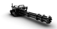
Mini Gun
...mini gun
3docean
gatling gun gun machine gun mini gun weapon
model of a mini gatling gun.
3ddd
free
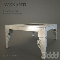
Herve mini
... кофейный , herve
http://www.mobiliavenanti.it/ru/products/hervè-mini
3d_export
$5
mini wall
...mini wall
3dexport
mini wall for living room
3d_export
$5

mini bank
...mini bank
3dexport
mini bank 3d model
Adapter
3d_export
$10
Adapter 3D Model
...adapter 3d model
3dexport
adapter
adapter 3d model mur 20260 3dexport
archive3d
free
Adapter socket 3D Model
...dapter socket adapter
adapter socket n090211 - 3d model (*.3ds) for interior 3d visualization.
turbosquid
$400

cell adaptation
...
royalty free 3d model cell adaptation for download as blend on turbosquid: 3d models for games, architecture, videos. (1701655)
archive3d
free
Adapter 3D Model
...ups pc equipment
adapter extron n180813 - 3d model (*.gsm+*.3ds) for interior 3d visualization.
turbosquid
$5

usb adapter
...royalty free 3d model usb adapter for download as ige and stl on turbosquid: 3d models for games, architecture, videos. (1582234)
turbosquid
$15
Power adapter
...free 3d model power adapter for download as max, obj, and fbx on turbosquid: 3d models for games, architecture, videos. (1510024)
turbosquid
$8
USB adapter
...e 3d model usb adapter for download as max, fbx, obj, and dwg on turbosquid: 3d models for games, architecture, videos. (1713542)
turbosquid
$30
adapter.3ds
... available on turbo squid, the world's leading provider of digital 3d models for visualization, films, television, and games.
turbosquid
$15
Nokia Adapter
... available on turbo squid, the world's leading provider of digital 3d models for visualization, films, television, and games.
turbosquid
$15
Universal adapter
... available on turbo squid, the world's leading provider of digital 3d models for visualization, films, television, and games.
Power
turbosquid
$100
power
...ower
turbosquid
royalty free 3d model power for download as on turbosquid: 3d models for games, architecture, videos. (1421990)
3d_export
$5

Power
...power
3dexport
3d_export
$5
power outlets
...power outlets
3dexport
power outlets
3ddd
$1
lion power
...lion power
3ddd
лев , статуя
lion power gold sculpture
3ddd
$1
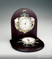
Sea Power
...
компас , море , часы
часы с компасом sea power
3ddd
free

Meridiani / Power
...power
3ddd
meridiani , круглый
стол power производитель meridiani, диаметр 120,высота 67
3d_export
$5

Power Surge
...power surge
3dexport
the power surge is a all mesh carnival ride to lower in game part count and lag
turbosquid
$8
Airport Ground Power Unit (AXA Power )
... available on turbo squid, the world's leading provider of digital 3d models for visualization, films, television, and games.
turbosquid
$50

Power Houser
...rbosquid
royalty free 3d model power houser for download as on turbosquid: 3d models for games, architecture, videos. (1333800)
3d_export
$5

power outlet
...power outlet
3dexport
power outlet<br>format file maya 2018, 3d max 2017, obj, fbx