Thingiverse
Parametric Processor (CPU) Delidding Tool by spikespaz
by Thingiverse
Last crawled date: 4 years, 2 months ago
About
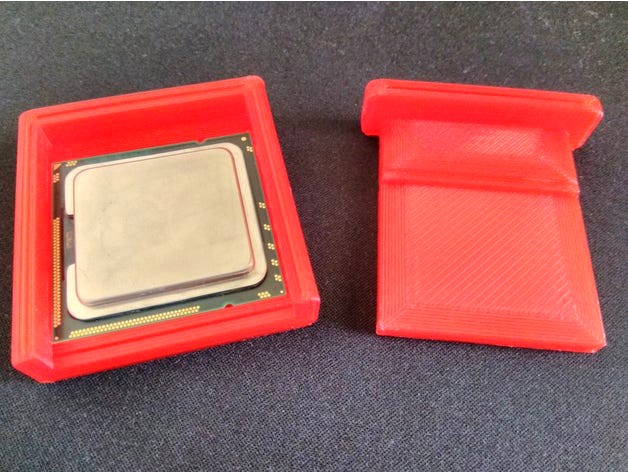
This is a customizable parametric processor delidding tool. Variables can be edited to fit any LGA (Land Grid Array) processors. PGA (Pin Grid Array) processors do not work with this tool.
Go to the Imgur album to see all of the pictures.
Note: For some reason, the previews for the tool base part aren't rendering properly. That is not how it will look when you print it. To see an accurate representation, look at the first screenshot of the OpenSCAD window, or the second render of the example STL file.
Customizing
You must customize this tool for your processor. The default settings are for an LGA1366 processor, which probably isn't what you're using.
Open the Customizer app, and change the variables to your processor's measurements. You probably don't need to change any in the box-margins tab.
If you are confused about any of the parameters, all you need to do is ask for clarification.
Note: When measuring the CPU, enter a little extra room, about ±0.2mm on the width and depth, if your prints shrink. If you have great dimensional accuracy you probably shouldn't worry.
Instructions
Lay the processor inside of the tool base as you would for a motherboard socket.
Place the tool cover over the top of the processor so the ridge underneath butts against the edge of the processor's IHS.
The underside of the cover (facing up when printed) should be flush against the top of the processor.
There should be a gap between the inner edge of the tool base and cover the same length as the margin (default: 5) specified in the variables.
The top side of the cover and base should be flush with each other.
Use a C-clamp or equivalent to press the base and cover together.
The threaded side of the clamp should be pushing down on the top of the cover.
The non-mobile part of the clamp should be on the bottom of the base.
Tighten the clamp securely, don't be afraid to put pressure on the processor. If there isn't enough pressure, the cover may slip and break during the next step.
Place the tool in a vice, lengthwise. This will put pressure on the side of the PCB and IHS to separate the silicon seal between the two.
The C-clamp will be perpendicular to the force of the vice.
Slowly close the vice until you feel or hear the silicon seal break. There should be an audible snap, and tension on the vice will be reduced suddenly. The gap between the two parts should also be gone.
You may want to hold the middle of the clamp while closing the vice, as when the seal snaps it may fall out of the vice.
Take the tool out of the vice, and carefully remove the clamp.
Hold the cover and base together while the clamp is removed.
Take the processor out carefully, preferably dump it in your hand upside-down. The IHS and PCB are now separate, and your warranty void.
You should know what to do after opening the processor. The rest is on you.
Disclaimer
Your warranty is now void.
This is a risky process, but potentially very beneficial. Your processor may break. If you don't know what delidding is, please research the topic thoroughly before proceeding.
You can delid processors without a lip on the IHS, just set lip_depth to 0. However, only do so for Intel processors. Do not delid AMD processors! All AMD chips are soldered with indium, so there is no reason to delid them anyways. See this video by der8aur if you want to know more.
I am not liable for any damage caused by this tool.