Thingiverse
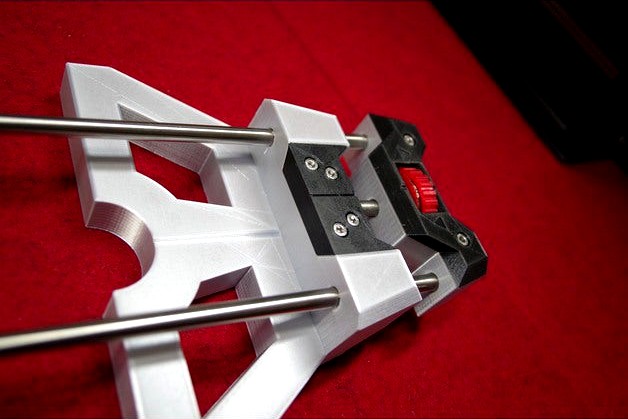
Parallel Guide for Bosch POF 1400 or 1200 by seikeinfrosch
by Thingiverse
Last crawled date: 3 years, 4 months ago
Hi guys!
A few days ago I wanted to print a parallel guide from another Thingiverse user but the result did not work for me (unusual material needed, imprecise rod fittings, …). So I took the challenge and tried to come up with something that fits to my needs.
This Parallel Guide is for the Bosch POF 1400 router (or Bosch POF 1200). It might fit to other routers that use 84mm distance between the rods, each rod 8mm in diameter.
Main features
Very sturdy and precise
Precise length adjustment with large wheel and scale on separate wheel (that can be set to zero)
Markers along the center of the guide for alignment (to be used like notch and bed sighter towards work piece)
Rods longer than the original parallel guide for more flexibility
Disclaimer
I used the some material (e.g. screws) available to me – see Material List. Due to tolerances of parts and 3D printing it might need some testing or tweaking on your side.
Material costs about 11 EUR plus 3D printing material
One turn of the adjust wheel equals 1.25mm (and not 1mm) due to standardized size of screw thread. Therefore the measurement label contains 0...1.25mm.
Detailed Steps
Print all parts once (see 3D printing hints, print rod caps two times)
For the Guiding Part…
2.1. Carefully remove the support structures from printing (especially from screw holes)
2.2. Insert the Carriage Bolt into the Guiding Part – Base.
2.3. Put the Guiding Part – Cap on top
2.4. Fix it using 4x M4 screws and nuts (and don‘t use too much force)
For the Adjust Wheel…
3.1. Carefully (!!!) remove the support structure from the Adjust Part (for the Washer)
3.2. Insert the M8 Screw Nut
3.3. Insert the Washers on each side (you might need a hammer for that – make sure they are slightly higher than the printed part, since they are the contact surfaces to the Base)
3.4. Clip on the Measure Part (make sure the settings ring is at the opposite side (Note: I added some masking tape on the shaft of the Adjust Part to make it fit and rotate smoothly)
For the Setting Part…
4.1. Check fittings direction of the rods in the Guiding Part (since holes and rods will be slightly non-symmetrical, so you‘ll find a preferred orientation)
4.2. Add a slight slit at the end of the rod to one side (approx. 6.5 … 7.5mm from end of the rod – see below for the reason and size of the slit)
4.3. Check orientation of the slits and insert into the Setting Part – Base (you might need to use a hammer)
4.4. Use the 2 smaller holes in the Base to insert Slim Nails or something like that. These nails will fix the rods tightly if done correctly. (If you have problems to find the slit, then look through the hole against a light source. Then you‘ll see if it is correct. And make sure the nails don‘t stick out of the bottom of the base to avoid injuries.)
4.5. Insert the previously prepared Adjust Wheel. (It will fit tight, but it will rotate. If it is loose, you‘ll have some unwanted backlash when adjusting.)
4.6. Put the Setting Part – Cap onto it (and check the alignment at the sides)
4.7. Fix it using 2x M4 screws and nuts (and don‘t use too much force)
You might complete your work adding the Rod Caps to the end of the rods.
Material List (additional)
2x50cm Rods (stainless steel, 8mm outer diameter, 6mm inner diameter for rod caps)
1x M8 Screw Nut
2x M8 Washers (about 20mm outer diameter)
1x M8x80 Carriage Bolt according DIN603 (80mm is the minimum length being useful)
6x M4x30 Hex Socket Cap Screws & Screw Nuts according DIN912 (or similar)
2 Slim Nails (or similar)
Office stuff (a printer for the label, adhesive tape, ...)
General
Start printing the smaller parts that need to fit to the material (e.g. nuts) to check fittings
I used simple PLA
Print in fine resolution (0.1mm)
Print with slight support (only connections from base)
Use Skirt (not brim)
Fit might be very tight (and adapted to the material I had at home) – so check your material
Be patient: in my case it was about 30h printing time (plus all my previous tries :-)
Printing Orientation & Color
Adjust Wheel – Adjust Part: Print with larger part on the heatbed. My color: red
Adjust Wheel – Settings Part: Print with the larger part on the heatbed. My color: red
Guiding Part – Base: Print with the large flat surface on the heatbed. My color: gray
Guiding Part – Cap: Print with the upper side (large screw holes) on the heatbed. My color: black
Setting Part – Base: Print with the upper side (screw holes) on the heatbed. My color: gray
Setting Part – Cap: Print with the larger side (bottom) on the heatbed. My color: black
Rod Cap: The small side (end inside the rod) on the heatbed. My color: red.
Adjust Wheel - Measure Part Label
Print the PDF file using („no resize“)
Cut it carefully
I used standard glue to fix it onto the Measure Part
And, I added some surface protection to the paper by using standard adhesive tape (but it carefully – no overlap is allowed)
Have fun & enjoy your woodwork!
Similar models
thingiverse
free

Parallel Stop for Bosch Router (POF 1400) (Parallelanschlag) by Niels1982
...as well as the rods. rod diameter is 8mm and the setting screw is m8x100. the printed parts are made from abs material @ 50 mm/s.
thingiverse
free

Anet A8 Hotbed Spring Cap (with m3 nut spacing) by Santonian
...printed this in pla which works fine for me, but if you regulary use a hotter hotbed, you might want to print this in abs or petg
thingiverse
free
Heatbed alignment system - Easy handling by DC_Engineering
...ve fun printing and enjoy the easy way of height adjustion.
if you have comments or worthy tips please let me know.
cheers c.
thingiverse
free

Spherical Bowden Filament Guide by yaikou
...sign that doesn't need a base and instead can be inserted into the v-slot rails, then rotated 90 degrees to lock it in place.
thingiverse
free

Phone Stand by LKBrilliant
...ll be less friction in the insert nut than the plastic. i simply heat the nut using my soldering iron and slide it into the hole.
thingiverse
free

Tevo Tarantula adjustable z stop by twb010
...supports.
do not use teeth to set locknut in insert!
extra parts used:
4x m4 screw
4x m4 t-nut
1x m3 screw
1x m3 nylon lock nut
thingiverse
free

Zonestar P802 heatbed adjustment wheel and spring guide by BomanXIX
...wheels takes in a m3 nut and make it easier to level the bed.
the spring guides stop the bed leveling springs from moving around.
thingiverse
free

Adjustable feet for Robotdigg SCARA Arm 3D Printer by dc42
...lutions.wordpress.com/2017/08/09/testing-the-robotdigg-scara-arm-3d-printer/ for how to strengthen the base frame of the printer.
thingiverse
free

ultimaker lead screw block by le_slash
...ad screw & bolt with a std. lead screw & nut.
print this piece and put nuts on top of it and insert the piece in heatbed.
thingiverse
free

Guide Rail Adapter for router by wiego
...ectly fit in the guide rail.
a m6 hex head screw, spacer and wing nut is needed in order to fix both parts in the right position.
Pof
turbosquid
$10

Connubia CB5207 Pof Pouf
...ty free 3d model connubia cb5207 pof pouf for download as max on turbosquid: 3d models for games, architecture, videos. (1655152)
turbosquid
$29

Lounge Chair
...lounge chair turbosquid royalty free 3d model pof chair for download as 3ds, max, obj, and fbx...
thingiverse
free

Bosch POF 1200 microlift knob by Gnomeg
...bosch pof 1200 microlift knob by gnomeg
thingiverse
microlift knob to unblocked microlift on bosch pof 1200
thingiverse
free

bosch pof 1200 ae micro adjustment knob by printsometools
...bosch pof 1200 ae micro adjustment knob by printsometools
thingiverse
micro adjustment knob for bosch pof 1200 ae router
thingiverse
free

Bosch POF 1400 ACE router extension by Kaworru
...giverse
this router extension for the bosch pof 1400 increases the contact surface which makes it more stable and easier to use.
3dbaza
$3

Connubia CB5207 Pof Pouf (115502)
...imensions: 470 x 470 x h480 mm<br>3dsmax 2016/2013 corona; .fbx; .obj; .3ds; .dxf; .dwg<br>polys: 11100; verts: 11505
thingiverse
free

Absaugung für Bosch Oberfräse POF 500 A by TruetechHD
...ür 30mm absaugschlauch.
schlauch:https://www.amazon.de/gp/product/b084hby4kx/ref=ppx_yo_dt_b_asin_title_o00_s00?ie=utf8&psc=1
thingiverse
free

Bosch POF 1400 ACE guide rail adapter by coreware
... remix of the "bosch pof 1400 ace router base plate" with the addition of a guide rail adapter for a makita guide rail.
thingiverse
free

Bosch POF 1400 ACE collet holder by ale5701
...laces for milling cutters that are provided in the storage case. the holders have dimensions of 8 mm., 6 mm., 6.4 mm. (1/4 inch).
thingiverse
free

BOSCH POF 1200 AE - Fine adjustment by alexbn
...osch pof 1200 ae - fine adjustment by alexbn
thingiverse
this is my version with the tenths notches, colored with white uniposca
1400
3ddd
$1
Smoke-Eucalyptus 1400 х 1400
...smoke-eucalyptus 1400 х 1400
3ddd
smoke-eucalyptus 1400 х 1400 texture
3ddd
$1

Natural Apple 1400 х 1400
...natural apple 1400 х 1400
3ddd
natural apple 1400 х 1400 текстура map texture
3ddd
$1
Glazed Stripewood 1400 х 1400
...glazed stripewood 1400 х 1400
3ddd
glazed stripewood 1400 х 1400 текстура map texture
3ddd
$1

Natural Spalted Maple 1400 х 1400
...natural spalted maple 1400 х 1400
3ddd
natural spalted maple 1400 х 1400 map texture текстура
3ddd
$1
Brandy Comet 1400 х 1400
...brandy comet 1400 х 1400
3ddd
brandy comet wood дерево текстура
design_connected
$16

Jason 1400
...jason 1400
designconnected
walter knoll jason 1400 chairs computer generated 3d model. designed by eoos.
3ddd
free

Night Sky Silkwood 1400 х 1400
...night sky silkwood 1400 х 1400
3ddd
night sky silkwood дерево текстура
turbosquid
$15

human-1400
... available on turbo squid, the world's leading provider of digital 3d models for visualization, films, television, and games.
3ddd
$1

Favourite 1400-6P
...favourite 1400-6p
3ddd
favourite
модель люстры favourite 1400-6p. в архиве файлы в 2011 и 2014 версиях и obj-файл.
3ddd
$1

Favourite 1400-2W
...avourite 1400-2w
3ddd
favourite
модель настенного светильника favourite 1400-2w. в архиве файлы в 2011 и 2014 версиях и obj-файл.
Bosch
3ddd
$1

BOSCH
...bosch
3ddd
bosch , чайник
чайник bosch
3ddd
$1
Bosch
...dd
bosch , wlx20462by , стиральная машина
bosch
3ddd
$1
Bosch
...bosch
3ddd
bosch , печь
bosch hba 63 a 263 f
3ddd
$1

BOSCH
...bosch
3ddd
bosch , свч
встраиваемая микроволновая печь bosch hmt 85 mr 63
3ddd
$1

Bosch
... газовая плита , плита
варочная поверхность bosch ppq 726m90e.
3ddd
$1
bosch
...bosch
3ddd
стиралка , стиральная машина
стиральная машина bosch
3ddd
$1
Blender bosch
...blender bosch
3ddd
bosch , блендер
blender bosch
3ddd
$1
Миксер Bosch
...миксер bosch
3ddd
bosch , миксер
миксер bosch.
3ddd
$1
Bosch HBA23B250E
...bosch hba23b250e
3ddd
bosch , духовка
oven bosch-hba23b250e
3ddd
free

Комбайн BOSCH
...омбайн , bosch , кухонный комбайн
комбайн bosch
Parallel
3ddd
$1

Jacob Delafon - Parallel
... ванна , parallel
чугунная ванна parallel на ножках от производителя jacob delafon
turbosquid
$5

Parallels Pendant
...
royalty free 3d model parallels pendant for download as stl on turbosquid: 3d models for games, architecture, videos. (1528415)
turbosquid
$5
Parallels Coaster
...
royalty free 3d model parallels coaster for download as stl on turbosquid: 3d models for games, architecture, videos. (1528413)
turbosquid
$2

Parallel Bars
...free 3d model parallel bars for download as obj, c4d, and fbx on turbosquid: 3d models for games, architecture, videos. (1475515)
turbosquid
$5

Contra Parallels Pendant
...ty free 3d model contra parallels pendant for download as stl on turbosquid: 3d models for games, architecture, videos. (1528397)
turbosquid
$5

Contra Parallels Coaster
...ty free 3d model contra parallels coaster for download as stl on turbosquid: 3d models for games, architecture, videos. (1528395)
cg_studio
$40
Parallel bars3d model
... olimpic apparatus
.3ds .c4d .dxf .obj - parallel bars 3d model, royalty free license available, instant download after purchase.
3d_export
$40

Parallel bars 3D Model
...ulting horse parallel wall gym fitness sport equipment horizontal bar olimpic apparatus
parallel bars 3d model braz 8646 3dexport
turbosquid
$65

Parallel Twin Cable
... available on turbo squid, the world's leading provider of digital 3d models for visualization, films, television, and games.
3ddd
$1

Possini Euro Design Black Parallel
...possini euro design black parallel
3ddd
possini
possini euro design black parallel
1200
turbosquid
$12

HUMAN-1200
... available on turbo squid, the world's leading provider of digital 3d models for visualization, films, television, and games.
3ddd
$1

LAUFEN / CASE 1200
...laufen / case 1200
3ddd
laufen
модель мебели для ванной laufen серия case 1200, max2012+fbx+obj+3ds
3ddd
$1

RAVAK Unity 1200
...unity , suzan
умывальник ravak unity 1200
смеситель ravak suzan sn 012
полигонов 77 000
design_connected
$18

Pictofocus 1200 Gas Fireplace
...00 gas fireplace
designconnected
focus pictofocus 1200 gas fireplace computer generated 3d model. designed by imbert, dominique.
3ddd
$1
Kappellini Intagli 1200 PS
... капитоне , кресло
компютерне крісло kappellini intagli 1200 ps.159538 полігонів
turbosquid
$35

Kitchen Stove Bertazzoni 1200
...ee 3d model kitchen stove bertazzoni 1200 for download as upk on turbosquid: 3d models for games, architecture, videos. (1258217)
turbosquid
$35

Medieval Tower 1200 3D
...y free 3d model medieval tower 1200 3d for download as blend on turbosquid: 3d models for games, architecture, videos. (1454112)
turbosquid
$79

Ducati Monster 1200(1)
...model ducati monster 1200(1) for download as ma, obj, and fbx on turbosquid: 3d models for games, architecture, videos. (1376659)
turbosquid
$6

Classic wood table 1200
...del classic wood table 1200 for download as max, obj, and fbx on turbosquid: 3d models for games, architecture, videos. (1459507)
turbosquid
$6

Wooden table with veneers 1200
...den table with veneers 1200 for download as max, obj, and fbx on turbosquid: 3d models for games, architecture, videos. (1469151)
Guide
turbosquid
$15

Guide drawer
...squid
royalty free 3d model guide drawer for download as dwg on turbosquid: 3d models for games, architecture, videos. (1261387)
turbosquid
$1
Road Guide
... available on turbo squid, the world's leading provider of digital 3d models for visualization, films, television, and games.
archive3d
free
Guide-board 3D Model
...ion sign guide sign
guide-board n170112 - 3d model (*.gsm+*.3ds) for exterior 3d visualization.
turbosquid
$2

soap cutter guide
...
royalty free 3d model soap cutter guide for download as stl on turbosquid: 3d models for games, architecture, videos. (1694030)
turbosquid
$15

Blind Guiding tiles
...free 3d model blind guiding tiles for download as 3dm and dae on turbosquid: 3d models for games, architecture, videos. (1156598)
turbosquid
$69

Japanese Tour Guide
...d model japanese tour guide for download as max, fbx, and obj on turbosquid: 3d models for games, architecture, videos. (1614288)
turbosquid
$10
CNC Linear Guide
... available on turbo squid, the world's leading provider of digital 3d models for visualization, films, television, and games.
turbosquid
$1

Tank Model Guide
... available on turbo squid, the world's leading provider of digital 3d models for visualization, films, television, and games.
turbosquid
$1

Road Guide 2
... available on turbo squid, the world's leading provider of digital 3d models for visualization, films, television, and games.
3d_ocean
$9

Guide Books 3
...sformed separately and each have unique texture map on front and back cover. to make your work easier this model comes in thre...