Thingiverse

Paddlewheel speed log by humberto_mb
by Thingiverse
Last crawled date: 4 years, 1 month ago
INTRODUCTION
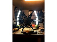
This is a design of a simple paddlewheel based speed log. The working procedure of the speed log is similar to those commercially available for boats ands yachts, but at a smaller scale. The incoming flow of water makes the impeller rotate. Each of the impeller paddles contains a small magnet. A simple electronics board counts each time a magnet passes the top most part. The velocity of the vessel over the water is proportional to the count (in reality it is not proportional, but for the intended use is perfectly fine to assume proportionality).
The intended use of this design is two-fold: for the one hand showing how these systems work; for the other hand, allowing the use of a simple and inexpensive speed log for small DIY crafts.
Although the use of a small size GPS could do much the same with more accuracy, I have developed this for use in a small size low-cost ROV (Remotely Operated Vehicle) for underwater exploration. There, there is no GPS at all.
The code and schematics for the Arduino based electronics are freely available in my GitHub account:
https://github.com/humbertomb/arduSpeedLog
MATERIALS
1 x Upper part case, for the electronics (printed, PLA)
2 x Lower part case, for the impeller (printed, PLA)
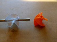
1 x Impeller (printed, PLA)
4 x Small circular magnets (5 mm diameter, 0.1 mm thickness)
1 x M3 bolt 15 mm
1 x M3 locknut
2 x M3 washers
BUILDING
I printed all the parts with a XYZ Davinci Jr, low infill (10%). Very solid and accurate.
The three parts for the case have been printed using white though PLA (although regular PLA could have been enough, I just run out of it). The impeller has been printed using orange translucent PLA.
I started printing the impeller. I re-drilled the axle hole with a 3mm drill. Then glued in place the magnets (on top of each paddle) and the washers (on the axle hole) using cyanoacrylate. Then I printed the two lower part halves and the upper part. Then I glued the three together using cyanoacrylate.
Last I fitted the impeller inside and pulled the bolt trough the axle hole and firmed it using the locknut. Do not tighten too much the locknut, otherwise the impeller will not spin freely.
This is a design of a simple paddlewheel based speed log. The working procedure of the speed log is similar to those commercially available for boats ands yachts, but at a smaller scale. The incoming flow of water makes the impeller rotate. Each of the impeller paddles contains a small magnet. A simple electronics board counts each time a magnet passes the top most part. The velocity of the vessel over the water is proportional to the count (in reality it is not proportional, but for the intended use is perfectly fine to assume proportionality).
The intended use of this design is two-fold: for the one hand showing how these systems work; for the other hand, allowing the use of a simple and inexpensive speed log for small DIY crafts.
Although the use of a small size GPS could do much the same with more accuracy, I have developed this for use in a small size low-cost ROV (Remotely Operated Vehicle) for underwater exploration. There, there is no GPS at all.
The code and schematics for the Arduino based electronics are freely available in my GitHub account:
https://github.com/humbertomb/arduSpeedLog
MATERIALS
1 x Upper part case, for the electronics (printed, PLA)
2 x Lower part case, for the impeller (printed, PLA)
1 x Impeller (printed, PLA)
4 x Small circular magnets (5 mm diameter, 0.1 mm thickness)
1 x M3 bolt 15 mm
1 x M3 locknut
2 x M3 washers
BUILDING
I printed all the parts with a XYZ Davinci Jr, low infill (10%). Very solid and accurate.
The three parts for the case have been printed using white though PLA (although regular PLA could have been enough, I just run out of it). The impeller has been printed using orange translucent PLA.
I started printing the impeller. I re-drilled the axle hole with a 3mm drill. Then glued in place the magnets (on top of each paddle) and the washers (on the axle hole) using cyanoacrylate. Then I printed the two lower part halves and the upper part. Then I glued the three together using cyanoacrylate.
Last I fitted the impeller inside and pulled the bolt trough the axle hole and firmed it using the locknut. Do not tighten too much the locknut, otherwise the impeller will not spin freely.
Similar models
cults
free

18mm diameter impeller for 3mm shaft
...t a slow speed and use cooling for best quality.
also useful as a small benchmark print to test for fine details and overhangs.
thingiverse
free

Paddle shifter by annttu
...ww.thingiverse.com/thing:4706673 but can be attached to other mounts too.
assembly instruction video https://youtu.be/-902n7sj2le
thingiverse
free
18mm diameter impeller for 3mm shaft by finhudson16
... at a slow speed and use cooling for best quality.
also useful as a small benchmark print to test for fine details and overhangs.
thingiverse
free
Magnetic "Coffin's Half Hour Cube" with base by thing_maker
... print has to be paused before the inner holes will closed.
i have used this magnets: https://www.amazon.de/gp/product/b00hxlbh6k
thingiverse
free

7 Inch LCD Case by dawg645
...ional)
1 each - thinge (support arm - optional)
1 each - thingf (foot - optional)
pla 100% infill, no supports or rafts required.
thingiverse
free

Small Handle for Needle Files (∅4 mm) by sbandi
...l), then glue the shells together and cups to the ends with expoxy or cyanoacrylate glue. finally put a m3×8 screw into the hole.
cg_trader
$8

Small Turbocharger | 3D
...snail.
assembled with 7 m3 screws. assembly is very easy.
it can be printed from pla, petg, abs, composite materials and others.
thingiverse
free

Fanatec WRC Steering Wheel Magnetic Paddle Shifters by Stuyo
...ng holes.
here is the design in tinkercad:https://www.tinkercad.com/things/cntf0y9bgho-fanatec-wrc-wheel-magnetic-paddle-shifters
thingiverse
free

Electronic Case for AGraber by edulago
...crews.
holes for electronic fixing are 2.5mm diameter as the holes in cover. they are perfect size to use a m3 thread tool (tap).
thingiverse
free

BIGTREETECH TFT35 V3.0 Case
...an add it if needed.
alternative mounting adapters:ender 5 by dareknorway
change log
added part 2 of mount.
added part 1 of mount
Paddlewheel
turbosquid
$75

Paddlewheel Boat
... available on turbo squid, the world's leading provider of digital 3d models for visualization, films, television, and games.
turbosquid
$17

PaddleWheel.3DS
... available on turbo squid, the world's leading provider of digital 3d models for visualization, films, television, and games.
thingiverse
free

Paddlewheel RC boat by DzikuVx
...ddleboat. to power paddlewheels you will need 2 continuousrotation servos. or regular 9g servos converted to continuous rotation.
thingiverse
free
Paddlewheel by skalski
... grabcad.
i have printed this and can confirm it works great on my sidewheeler, and have been working great for the last 3 years!
thingiverse
free

Feathering Paddlewheel by skalski
...
for assembly you will need 33pcs of m2x6mm and 10pcs of m2x10mm screws.
you will also need to cut 11 pcs of 3x41mm plastic rod.
sketchfab
$72
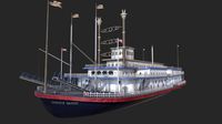
Steamboat Creaole Queen / Natchez
.../ natchez sketchfab steamboat creole queen / natchez - paddlewheelr model. - steamboat creaole queen / natchez - buy...
thingiverse
free
Paddle Wheel for eBike Hub Motor (9C front hub) by AmpEater
...turn an ebike hub motor into a powerful electric paddlewheel it's designed to fit a 9 continents front hub...
thingiverse
free

The Red Scourge Reimagined by sleyvas
...by sleyvas thingiverse the red scourge was an enormous paddlewheeld vessel from thay that patrolled the alamber sea. boasting...
renderosity
$12

USS Neosho River Monitor
...has erc control at the body level:<br /> o paddlewheel and engines operate realistically<br /> o rudders and helm...
Humberto
3ddd
free

Favela by edra
...edra 3ddd edra favela manufacturer edra designer fernando & humberto campana launched in...
3ddd
$1

edra Scrigno sideboard
...sideboard 3ddd edra , scrigno , тумба fernando and humberto campana 2009 scrigno sideboard. scn020 mobile basso container...
3ddd
$1

EDRA Corallo Bed, beds division
...edra corallo bed, beds division, corallo bed fernando and humberto campana...
3d_export
$54

Designer Sofa by edra 3D Model
...3dexport edra sofa divan settee modern fashionable fernando campana humberto contemporary massimo morozzi interior armchair folds natural leather upholstery...
3d_export
$49

BOA Designer Sofa by edra 3D Model
...settee divan italy velvet upholstery snakes tubes fernando campana humberto contemporary modern design boa designer sofa by edra 3d...
cg_studio
$45

BOA Designer Sofa by edra3d model
...settee divan italy velvet upholstery snakes tubes fernando campana humberto contemporary modern design interior sofa lounge .obj .max .fbx...
3ddd
$1
Miraggio - Edra
...знаменитых бразильских дизайнеров фернандо и умберто кампана (fernando and humberto campana). изделие выполнено из цветного акрилового полимера с зеркальной...
unity_asset_store
$6

Barbarian Warrior by Humberto C Jr
...rrior by humberto c jr asset from humberto cardoso junior. find this & other characters options on the unity asset store.
thingiverse
free

Filament Reel by humberto
...filament reel by humberto
thingiverse
a small reel to hold filament (approx 1/2 kg).
thingiverse
free

iPad (& such) stand by humberto
...nd store ipad and tablet stand. very usefll to use the tablet in many settings, for instance like and extra screen (see pictures)
Log
3d_export
$5

log
...log
3dexport
log obj,fbx, blend
archibase_planet
free

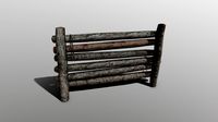
Logs
...se planet
pile stack of firewood pile of logs stack firewood
logs n230511 - 3d model (*.gsm+*.3ds) for exterior 3d visualization.
turbosquid
$12

Logs
... logging trees wood rings lumberyard for download as max on turbosquid: 3d models for games, architecture, videos. (1581124)
turbosquid
$29
Logs
...gs
turbosquid
royalty free 3d model logs for download as max on turbosquid: 3d models for games, architecture, videos. (1249348)
3ddd
$1
LOGS WALL
...logs wall
3ddd
logs wall , big white
big white "logs wall"
3d_export
$5
Log
...log
3dexport
turbosquid
$3

Log
...
royalty free 3d model log for download as max, obj, and fbx on turbosquid: 3d models for games, architecture, videos. (1382640)
turbosquid
free

Log
...
royalty free 3d model photo-scanned log for download as fbx on turbosquid: 3d models for games, architecture, videos. (1395110)
turbosquid
$15

Log
... available on turbo squid, the world's leading provider of digital 3d models for visualization, films, television, and games.
turbosquid
$10

logs
... available on turbo squid, the world's leading provider of digital 3d models for visualization, films, television, and games.
Speed
turbosquid
$50

speed
... available on turbo squid, the world's leading provider of digital 3d models for visualization, films, television, and games.
turbosquid
$50

speed
... available on turbo squid, the world's leading provider of digital 3d models for visualization, films, television, and games.
turbosquid
free

speed
... available on turbo squid, the world's leading provider of digital 3d models for visualization, films, television, and games.
3d_ocean
$8
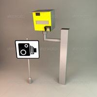
Speed Camera
...model is separate and named appropriately. this is perfect for any type of scene from a road side, architectural or motorway s...
turbosquid
$25

Speed Buggy
...urbosquid
royalty free 3d model speed buggy for download as on turbosquid: 3d models for games, architecture, videos. (1209512)
turbosquid
$4

Speed Sign
...turbosquid
royalty free 3d model speed sign for download as on turbosquid: 3d models for games, architecture, videos. (1251518)
3d_export
$10
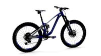
variable speed bicycle
...variable speed bicycle
3dexport
variable speed bicycle
3d_export
$5
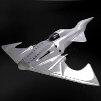
High - speed aircraft
...high - speed aircraft
3dexport
high speed plane
turbosquid
$185
Speed Boat
... free 3d model speed boat for download as skp, blend, and obj on turbosquid: 3d models for games, architecture, videos. (1606216)
turbosquid
$5
Speed bag
...y free 3d model speed bag for download as blend, obj, and stl on turbosquid: 3d models for games, architecture, videos. (1577878)
Mb
3ddd
$1
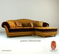
MB Style / Alexander
...mb style , угловой
http://www.bmstyle.it/
модель: alexander
фабрика: mb style
3ddd
$1

MB Style / Eloise
...dd
mb style , угловой
http://www.bmstyle.it/
фабрика: mb style
модель: eloise
3d_export
$6

mb-actros-containersnapshot5
...mb-actros-containersnapshot5
3dexport
mb-actros-container.snapshot.5
turbosquid
$150

Radio_Telescope_2.mb
... available on turbo squid, the world's leading provider of digital 3d models for visualization, films, television, and games.
turbosquid
$150

RatMA+MB
... available on turbo squid, the world's leading provider of digital 3d models for visualization, films, television, and games.
turbosquid
$99

bear_v8.mb
... available on turbo squid, the world's leading provider of digital 3d models for visualization, films, television, and games.
turbosquid
$75

virtualSet2.mb
... available on turbo squid, the world's leading provider of digital 3d models for visualization, films, television, and games.
turbosquid
$70

mol5.mb
... available on turbo squid, the world's leading provider of digital 3d models for visualization, films, television, and games.
turbosquid
$65

ktprktpr_whitemale01.mb
... available on turbo squid, the world's leading provider of digital 3d models for visualization, films, television, and games.
turbosquid
$65

female01.mb
... available on turbo squid, the world's leading provider of digital 3d models for visualization, films, television, and games.