GrabCAD

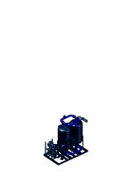
Oxygen Flow Rate Splitter
by GrabCAD
Last crawled date: 1 year, 10 months ago
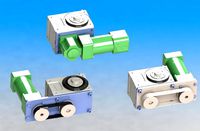
Pretty sure this one fills the brief. It uses existing Nasal Cannulas. The cannula connection end is threaded through the square slide and then pushed onto the barb at the top of the Oxygen Flow Splitter. This is done for both sides. The slide is then forced past the closed position on the carriages. The Flow Splitter can then be fitted to the Oxygen Regulator. The slides will squeeze the cannula to restrict the flow and can be regulated to flow rates via the embossed numbers along the slide carriages. The small grooves on the slide and the back of the carriage plus the expansion pressure of the tubing will keep the slides in position. Set the Oxygen regulator to the sum of the desired flow rate of both patient requirements and then set the splitter slides to suit, e.g. one patient requires 4 l/m and the other requires 3 l/m, set the Oxygen regulator to 7 l/m and the slides to 3 & 4 l/m respectively. The range of flow is from full open to full closed in 1 litre/minute increments. The hooks on the side can be used as storage for the cannulas when not being used. No chance of oxygen leakage as there are no breaks in the line from regulator to patient. Footprint is 137 mm x 140 mm x 33 mm.
Can be easily 3D printed and main carriage body is hollow to reduce print time, weight and material expense.
Total weight of assembly without the cannulas is approximately 60 grams (2 oz)
Can be easily 3D printed and main carriage body is hollow to reduce print time, weight and material expense.
Total weight of assembly without the cannulas is approximately 60 grams (2 oz)
Similar models
grabcad
free

Slide rule oxygen splitter
...e pipe to avoid crushing...
this design was created as part of my work for field ready but has not yet been tested in the field.
grabcad
free

Oxygen Valve Splitter
...s, compatible with standard nasal cannulas (id=5mm).
easy to hang.
printable on a 110mm x 90mm print bed.
colors are optional.
grabcad
free

Oxygen Splitter
...t : body 21.65 gr ; ball valve 1.34 gr ; one way ball 2x0.25 gr ; one way sping 2x0.05 gr ; total 23.3 gr.
port size : dia 0.4 in
grabcad
free

O2 Valve Splitter
...rted caps that adjusts the outlet area.
3d printable [abs] - vertically printed
prototype printed with xyzprinting da vinci 1.0
grabcad
free

Oxygen Flow Rate Splitter_Version_2
... need and the quantity of canulas on hand are restricted. abs plastic.
total weight for splitter plus both thumbwheels = 11 grams
grabcad
free

Oxygen Valve Splitter
...sisted with two parts, fixed and sliding.
the sliding parts can regular the flow of oxygen.
dimensions of model 34 x 46 x 11 mm.
grabcad
free

Custom Bleed Valve and Flow Splitter
...if the technician is able to group patients with similar oxygen needs. they can do the math quickly in...
grabcad
free

GMF - Oxygen Valve Splitter
...ed to the cannula.
overall body size could be reduced depending on the pipe diameter - i have assumed a 6mm dia pipe to cannula.
grabcad
free

Oxygen Splitter V2
...le model can be print and used without support or post-processing
-parametric design for easily remodeling
bondye beni ayiti
grabcad
free

Concept- Twin-O
...xygen is allowed to flow. but, some loss of oxygen is inevitable.
files ready to print without support, diameters are arbitrary.
Splitter
3d_export
$7
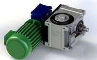
je-70df series splitter
...je-70df series splitter
3dexport
je-70df series splitter
3d_export
$8
Splitter wood
...splitter wood
3dexport
triangles 138k vertices 69.4k pbr no textures 3 materials 2 uv layers yes
turbosquid
free
Electrical Outlet electric splitter
... available on turbo squid, the world's leading provider of digital 3d models for visualization, films, television, and games.
3d_export
$7
je-80df series cam splitter 6 specifications
...ditional mechanism such as geneva mechanism, ratchet mechanism, incomplete gear mechanism, pneumatic control mechanism and so on.
3d_export
$300
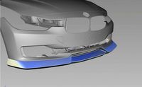
F30 front lip
...f30 front lip 3dexport front splitter for of exterior, based on real scan file. you...
3d_export
$13

3d cake cutter separator cake splitter equalizer slicer kitchen model
...ese evenly sliced pieces of cake look great in diner cases, refrigerated bakery displays, buffets, and other foodservice settings
3d_export
$10
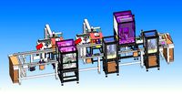
automobile door lock production line
...various classic manipulators, vibrating plate feeding, jacking mechanism, cam splitter mechanism. the design of the mechanism covers most of...
3d_export
$120
create micro circuit breaker fuse assembly equipment with dfm
...workflow: 1. equipment<br>internal turntable position, 2. module grip carrier<br>location,<br>3. splitter is 36 stations, 4. station loading, clamping,<br>it is supplied...
3d_export
$10

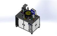
usb automatic assembly device
...the equipment includes a variety of mechanical design structures, splitter conveyor belt drive, manipulator grasping system and trough type...
3d_export
$29
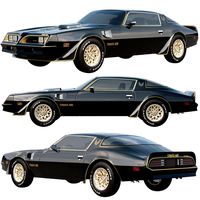
pontiac firebird trans am 1977
...standard equipment includes a rear decklid spoiler, dual chrome splitter exhaust extensions, and a front air dam. the interior...
Oxygen
archibase_planet
free

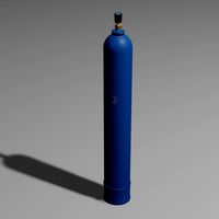
Oxygen tank
...ygen tank oxygen cylinder oxygen storage oxygen
oxygen tank n080615 - 3d model (*.gsm+*.3ds+*.max) for interior 3d visualization.
turbosquid
$23

Oxygene
...turbosquid
royalty free 3d model oxygene for download as fbx on turbosquid: 3d models for games, architecture, videos. (1501492)
3d_export
$5
Oxygen tank
...oxygen tank
3dexport
oxygen tank
archive3d
free

Oxygen tank 3D Model
...torage oxygen
oxygen tank n080615 - 3d model (*.gsm+*.3ds+*.max) for interior 3d visualization.
turbosquid
$2

Oxygen Tank
...royalty free 3d model oxygen tank for download as obj and fbx on turbosquid: 3d models for games, architecture, videos. (1174416)
turbosquid
free

Oxygen Cylinder
...lty free 3d model oxygen cylinder for download as fbx and obj on turbosquid: 3d models for games, architecture, videos. (1637893)
3d_ocean
$12
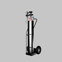
oxygen cylinder
...ical object ocean oxygen pressure recreational regulator research science silver steel tank valve
3d oxygen cylinder and material
turbosquid
$18

Oxygen bottle
... available on turbo squid, the world's leading provider of digital 3d models for visualization, films, television, and games.
turbosquid
$12

Oxygen Tanks
... available on turbo squid, the world's leading provider of digital 3d models for visualization, films, television, and games.
turbosquid
$3

oxygen container
... available on turbo squid, the world's leading provider of digital 3d models for visualization, films, television, and games.
Flow
turbosquid
free

Flow(Fluid/Flow)
... available on turbo squid, the world's leading provider of digital 3d models for visualization, films, television, and games.
3ddd
$1

Flow
...dd
flow , mdf italia , tessile
10 тыс.полигонов
turbosquid
$59

Blood Flow - Capilar flow
... available on turbo squid, the world's leading provider of digital 3d models for visualization, films, television, and games.
turbosquid
$59

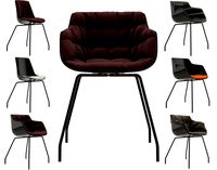
FLOW CHAIR and FLOW SLIM
... available on turbo squid, the world's leading provider of digital 3d models for visualization, films, television, and games.
turbosquid
$59

FLOW CHAIR and FLOW SLIM
... available on turbo squid, the world's leading provider of digital 3d models for visualization, films, television, and games.
turbosquid
$59

FLOW CHAIR and FLOW SLIM
... available on turbo squid, the world's leading provider of digital 3d models for visualization, films, television, and games.
turbosquid
$59

FLOW CHAIR and FLOW SLIM
... available on turbo squid, the world's leading provider of digital 3d models for visualization, films, television, and games.
turbosquid
$59
FLOW CHAIR and FLOW SLIM
... available on turbo squid, the world's leading provider of digital 3d models for visualization, films, television, and games.
turbosquid
$59

FLOW CHAIR and FLOW SLIM
... available on turbo squid, the world's leading provider of digital 3d models for visualization, films, television, and games.
3d_export
$5

Flow
...flow
3dexport
Rate
3d_ocean
$2

Rating Icons
...ution renderings and render scene are included to get you started quickly. obj files are included also which can be loaded int...
turbosquid
$6

Plastic part for vacuum rate
...stic part for vacuum rate for download as ige, stl, and sldpr on turbosquid: 3d models for games, architecture, videos. (1313742)
3d_export
$5
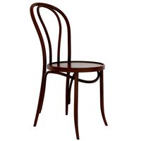
michael thonet rating chair1
...me! if you like this collection don't forget to rate it please - enjoy hope you like it! the...
3d_export
$5

michael thonet rating chair
...me! if you like this collection don't forget to rate it please - enjoy hope you like it! the...
3d_export
$5

michael thonet rating chair
...me! if you like this collection don't forget to rate it please - enjoy hope you like it! the...
3d_export
$5

michael thonet rating chair
...me! if you like this collection don't forget to rate it please - enjoy hope you like it! the...
3d_export
$15
Air Dryer Dalgakiran with a flow rate of 14667 m3 per minute
...f 14667 m3 per minute
3dexport
air dryer dalgakiran with a flow rate of 146.67 m3 per minute and dew point - 40 degrees celsius
3d_export
$5

Heart Rate Monitor
...ad our <br>. you will received:<br>- 1 objects<br>- jpg (2000 x 2000px)<br>- obj file<br>- mtl file
3d_export
$10

Compressor Dalgakiran flow rate 45m3 per minute
...compressor dalgakiran flow rate 45m3 per minute
3dexport
compressor dalgakiran, with a constant air capacity of 45m3 per minute
3d_export
$149

first rate ship of the line hms prince 1670
... a 100-first rate ship of the line of the royal navy, built by phineas pett the younger at deptford dockyard and launched in 1670