Thingiverse
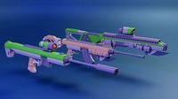
Onewheel Battery Pack (The Lifejacket)
by Thingiverse
Last crawled date: 4 years, 2 months ago
Hiya~
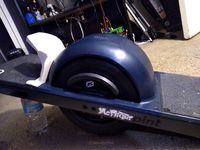
Been wanting to have a way to charge my Onewheel when out for a while. Since I have an electric bike I felt it would make sense to be able to use the battery from it on the battery pack. This is my 6th major iteration of a portable battery and hopefully my last, since it's up to my standard of simplicity and usefulness I figured now would be a good time to share with the community.
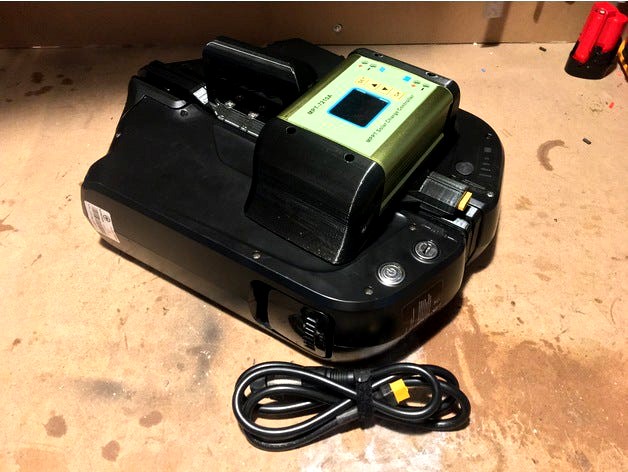
This allows me to fast charge the Onewheel on the go. It just fits in my backpack so allows me to keep floating for longer (hence the dumb name).
The design allows you to attach 2 36v 14.5Ah batteries back to back while using a solar charge controller to boost the voltage and safely charge the Onewheel. For more information on the topic of portable charging for the Onewheel visit the below.https://onewheel.wiki/Charging_on-the-go
~ THINGS YOU'LL NEED ~
A drill
Soldering Iron and solder
Philips screwdriver
Allen keys
2x Rail_Mount.stl
1x MPPT_Mount.stl
2x Wire_Cover.stl
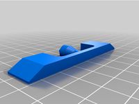
1x Handle.stl
2x 36v 14.5Ah ebike batteries (https://www.amazon.co.uk/dp/B07NV9ZZFG). There is a 12Ah version which is much cheaper if you don't need crazy amounts of juice.
1x MPT 7210A Solar Controller (https://www.amazon.co.uk/dp/B07J3W79DB)
6x M5 x 25mm Pozi Pan Bolt (https://www.amazon.co.uk/dp/B07XFQ2NWC)
10x M5 x 22mm Countersunk Bolt (https://www.amazon.co.uk/dp/B07RWKPQ7H)
4x M5 x 16mm Countersunk Bolt (https://www.amazon.co.uk/dp/B07RYZ2NY3)
1x M5 x 90mm Cap Head Bolt (https://www.amazon.co.uk/dp/B01N2HPG7B)
21x M5 Hexagonal Nuts (https://www.amazon.co.uk/dp/B07BVX8QQ5)
4x M4 x 16mm Pozi Pan Bolt (https://www.amazon.co.uk/dp/B07BGCQ6BF)
4x M4 Hexagonal Nuts (https://www.amazon.co.uk/dp/B07MLP2C2W)
1x 3mm x 100mm Steel Rod (https://www.amazon.co.uk/dp/B00OK6GD9M)
1x 16AWG insulated wire (https://www.amazon.co.uk/dp/B07FN9G27L)
1x XLR cable (https://www.amazon.co.uk/dp/B0151R409S)
1x XT60 male and female connectors (https://www.amazon.co.uk/dp/B074RGT76J)
~ ASSEMBLY ~
Printing
Print the Rail_Mount.stl twice. DO NOT MIRROR this part, it is designed to rotate after the print and bolt together.
Print the MPT_Mount.stl as is, this should not require support.
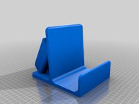
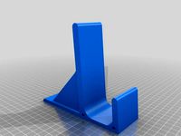
Print the Handle.stl. This may require support for the top overhang.
Print the Wire_Cover.stl. This may require support for the central overhang.
Adding Nuts
Take 3 nuts and place onto the central column of the Rail Mount leaving a gap between each. So from one end you might go nut, space, nut, space, nut, space. If the nuts don't quite fit use a bolt to pull the nut in from the other side.
Do the same on the other Rail Mount but with the opposite pattern, such as space, nut, space, nut, space, nut.
On the other sides of each Rail Mount add 2 nuts to each on the outer corners.
Perform a dry fit by placing the 2 rails together so that the nuts on the central column are not visible. Take the 4 M5 x 22mm Countersunk Bolts and fasten the 2 Rail Mounts together at the corners where there are 2 countersunk holes on each corner for both rails.
Rotate the rails so that the seem is now facing up. Both sides are the same so choose 1 and set that as your top. On the underside of the holes should be spaces to add a total of 10 nuts (ignore the ones on the bottom, those will be unused). Add the 10 nuts in the premade holes.
Take the MPT Mount and add the 4 M4 nuts to the underside.
Use the 4 M4 x 16mm Pozi Pan Bolts dry fit the MPPT Mount to the Rail Mount along the joining face you added nuts to the underside from earlier. The hole in the MPT Mount should align with the hole in the Rail Mounts with the XT60 hole pointing out of the shortest side.
Take the Handle and slide the 3mm rod down the small hole on the lower part of the Handle. It will be a tight fit so I suggest placing one end of the rod in a drill then using it to rotate the rod down. It will essentially melt its way down. Just before it reaches the other side saw off any excess and then tap the rest in till it's flush that side with none poking out the other side. This will add some shear strength to the lower part of the handle where the bolts sit.
Add an M5 Nut to the Handle in the premade hole, then screw down the M5 x 90mm Cap Head Bolt until it's threaded onto the nut. This doesn't need to be tight. If you do tighten it you may break the plastic. This is designed to add further shear strength to the upper part of the handle.
Add 6 M5 x 22mm Countersunk Bolts to the Handle and screw that down into the same side of the Rail Mounts as you did the MPT Mount. The taller side should be on the side of the MPT Mount.
Electronics
Make sure the batteries are removed from the battery rail.
The wiring that comes with the 36v 14.5Ah ebike batteries may not be long enough to reach the MPT controller so use the 16AWG wire to either extend it or replace it. 350-400mm should be long enough (from where it exits the rail all the way to the end). Tape them together with a label for later.
Solder 200-250mm of 16AWG wire to the male XT60 connector. I recommend putting the female end in the male connector while soldering to prevent the pins becoming misaligned. Tape them together with a label for later.
Thread the wire for the XT60 through the XT60 hole in the MPT Mount. Add some superglue to the lower sides of the XT60 and press it into the XT60 hole being sure to pull the wire through as you do as to not kink or trap it. It doesn't need to go all the way in.
Take the rails for the battery and pull the cables through the Rail Mounts so that the ends come out the hole in the MPT Mount.
Align the battery rails with the Rail Mounts. They should slot into the groove in which you can add 6 M5 x 25mm Pozi Pan Bolts (3 per rail) to fasten them down onto the rail mounts. Be sure to screw the the rails down in the correct nut. You want the nut to press up against that rail, not pull it out of the other rail. Tighten these down so that the rails are firm and won't risk detaching when carried.
Work the 6 wires (2 for the XT60 and 4 for the batteries) on the MPT Mount so that they follow the trench out to the side.
Using the Labels from earlier put the single positive wire for the XT60 in the positive battery terminal on the MPT controller. Then take the negative wire for the XT60 and connect that to the negative battery terminal on the MPT controller.
Take both positive wires for the batteries and connect them to the positive solar terminals on the MPT controller. Finally take both negaive wires for the batteries and connect them to the negative solar terminals on the MPT controller.
Charge Cable
Take the XLR cable and desolder the female end from the rest of it.
Cut some 16AWG wire to the length you want the charge cable to be. Mine is 1M for example.
Solder one end of the positive wire to pins 2 and 3 on the female XLR plug.
Solder one end of the negative lead to pin 1 on the female XLR plug.
Reassemble the XLR connector and slide up onto the wire any insulation/ sleeving/ heat shrink you want to use to complete the wire before adding the XT60.
Solder the positive terminal on the XT60 to the other end of the positive lead on the wire.
Solder the negative terminal on the XT60 to the other end of the negative lead on the wire.
Adjust the insulation/ sleeving/ heat shrink so that the charge cable is safe from shorting and no exposed wiring is visible.
Sanity Check.
Take a multimetre and set it to continuity test (with a beep if possible). Use this to probe between the positive and negative terminals of the XT60 to see if there is a short. Also test if there is a short across either of the battery rail connectors. Verify terminals on the MPT controller connect back to the correct place. Connect the charge cable to the XT60 on the MPT Mount and verify pins 2 and 3 on the XLR go back to the positive battery terminal on the MPT controller and that pin 1 goes back to negative. If anything is wired backwards, shorted or going to the wrong place now is the time to fix it! Failure to do this will end in tears.
Finishing Off.
Place the MPT controller on top of the MPT Mount so that the wires are pressed into the trench. If it does not sit flat try to move the wires so they do not overlap.
Take the 4 M4 x 16mm Pozi Pan Bolts and the 2 Wire Covers, placing the bolts into the 2 holes per wire cover.
Slot one over the side without the wires as this is the easiest. You should be able to put a screwdriver through the holes in the top of the over to eventually screw the covers down through the MPT mount and into the nuts on the underside of the MPT Mount.
Do the same with the other side that has the wires, be careful not to trap any of the wires or damage the insulation. Apologies that this step might be utterly infuriating trying to wiggle the screwdriver and bolt around the wires.
MPT Programming And Final Test
Slot 1 battery onto the battery rail and use the key to lock it in place so it doesn't slide off onto your foot.
Power it on and check the MPT controller turns on.
Program the MPT controller to the desired voltages and max current settings.I recommend reading the manual thoroughly on all settings and warnings.
You want to set the "solar" voltage to 36v assuming you used 36v batteries linked in above.
For the Onewheel and Onewheel + you want to set the target voltage to 58v and current to 3.5A
For the Onewheel + XR you want to set the target voltage to 63v and current to 3.5A
For the Onewheel Pint you want to set the target voltage to 63v and current to 1.3A
You can charge at a higher current but battery longevity can be shortened plus the wiring may become hotter with currents above this. Too hot and they could melt and short out.
With the settings dialled in connect the other battery and verify that when it is powered on that everything still works with no magic smoke.
Connect the charge cable and verify if the desired voltage is present on the XLR. Set your multimetre to DC voltage and place the negative probe in pin 1 and then the positive in pin 2. Verify the voltage and then try the positive probe in pin 3. If all looks good connect it up to your onewheel.
Open the Onewheel app and check the board is charging. The current on the MPT will climb steadily until it reaches a point in which it is happy for the current voltage. As the board charges the voltage will climb closer to the target voltage you set whilst the current will get lower and lower until it's met the target voltage.
That should be it, enjoy your Lifejacket, may it keep you floating for many more miles.
Please share any improvements or thoughts as I'm more than happy to try and improve on this further :)
Been wanting to have a way to charge my Onewheel when out for a while. Since I have an electric bike I felt it would make sense to be able to use the battery from it on the battery pack. This is my 6th major iteration of a portable battery and hopefully my last, since it's up to my standard of simplicity and usefulness I figured now would be a good time to share with the community.
This allows me to fast charge the Onewheel on the go. It just fits in my backpack so allows me to keep floating for longer (hence the dumb name).
The design allows you to attach 2 36v 14.5Ah batteries back to back while using a solar charge controller to boost the voltage and safely charge the Onewheel. For more information on the topic of portable charging for the Onewheel visit the below.https://onewheel.wiki/Charging_on-the-go
~ THINGS YOU'LL NEED ~
A drill
Soldering Iron and solder
Philips screwdriver
Allen keys
2x Rail_Mount.stl
1x MPPT_Mount.stl
2x Wire_Cover.stl
1x Handle.stl
2x 36v 14.5Ah ebike batteries (https://www.amazon.co.uk/dp/B07NV9ZZFG). There is a 12Ah version which is much cheaper if you don't need crazy amounts of juice.
1x MPT 7210A Solar Controller (https://www.amazon.co.uk/dp/B07J3W79DB)
6x M5 x 25mm Pozi Pan Bolt (https://www.amazon.co.uk/dp/B07XFQ2NWC)
10x M5 x 22mm Countersunk Bolt (https://www.amazon.co.uk/dp/B07RWKPQ7H)
4x M5 x 16mm Countersunk Bolt (https://www.amazon.co.uk/dp/B07RYZ2NY3)
1x M5 x 90mm Cap Head Bolt (https://www.amazon.co.uk/dp/B01N2HPG7B)
21x M5 Hexagonal Nuts (https://www.amazon.co.uk/dp/B07BVX8QQ5)
4x M4 x 16mm Pozi Pan Bolt (https://www.amazon.co.uk/dp/B07BGCQ6BF)
4x M4 Hexagonal Nuts (https://www.amazon.co.uk/dp/B07MLP2C2W)
1x 3mm x 100mm Steel Rod (https://www.amazon.co.uk/dp/B00OK6GD9M)
1x 16AWG insulated wire (https://www.amazon.co.uk/dp/B07FN9G27L)
1x XLR cable (https://www.amazon.co.uk/dp/B0151R409S)
1x XT60 male and female connectors (https://www.amazon.co.uk/dp/B074RGT76J)
~ ASSEMBLY ~
Printing
Print the Rail_Mount.stl twice. DO NOT MIRROR this part, it is designed to rotate after the print and bolt together.
Print the MPT_Mount.stl as is, this should not require support.
Print the Handle.stl. This may require support for the top overhang.
Print the Wire_Cover.stl. This may require support for the central overhang.
Adding Nuts
Take 3 nuts and place onto the central column of the Rail Mount leaving a gap between each. So from one end you might go nut, space, nut, space, nut, space. If the nuts don't quite fit use a bolt to pull the nut in from the other side.
Do the same on the other Rail Mount but with the opposite pattern, such as space, nut, space, nut, space, nut.
On the other sides of each Rail Mount add 2 nuts to each on the outer corners.
Perform a dry fit by placing the 2 rails together so that the nuts on the central column are not visible. Take the 4 M5 x 22mm Countersunk Bolts and fasten the 2 Rail Mounts together at the corners where there are 2 countersunk holes on each corner for both rails.
Rotate the rails so that the seem is now facing up. Both sides are the same so choose 1 and set that as your top. On the underside of the holes should be spaces to add a total of 10 nuts (ignore the ones on the bottom, those will be unused). Add the 10 nuts in the premade holes.
Take the MPT Mount and add the 4 M4 nuts to the underside.
Use the 4 M4 x 16mm Pozi Pan Bolts dry fit the MPPT Mount to the Rail Mount along the joining face you added nuts to the underside from earlier. The hole in the MPT Mount should align with the hole in the Rail Mounts with the XT60 hole pointing out of the shortest side.
Take the Handle and slide the 3mm rod down the small hole on the lower part of the Handle. It will be a tight fit so I suggest placing one end of the rod in a drill then using it to rotate the rod down. It will essentially melt its way down. Just before it reaches the other side saw off any excess and then tap the rest in till it's flush that side with none poking out the other side. This will add some shear strength to the lower part of the handle where the bolts sit.
Add an M5 Nut to the Handle in the premade hole, then screw down the M5 x 90mm Cap Head Bolt until it's threaded onto the nut. This doesn't need to be tight. If you do tighten it you may break the plastic. This is designed to add further shear strength to the upper part of the handle.
Add 6 M5 x 22mm Countersunk Bolts to the Handle and screw that down into the same side of the Rail Mounts as you did the MPT Mount. The taller side should be on the side of the MPT Mount.
Electronics
Make sure the batteries are removed from the battery rail.
The wiring that comes with the 36v 14.5Ah ebike batteries may not be long enough to reach the MPT controller so use the 16AWG wire to either extend it or replace it. 350-400mm should be long enough (from where it exits the rail all the way to the end). Tape them together with a label for later.
Solder 200-250mm of 16AWG wire to the male XT60 connector. I recommend putting the female end in the male connector while soldering to prevent the pins becoming misaligned. Tape them together with a label for later.
Thread the wire for the XT60 through the XT60 hole in the MPT Mount. Add some superglue to the lower sides of the XT60 and press it into the XT60 hole being sure to pull the wire through as you do as to not kink or trap it. It doesn't need to go all the way in.
Take the rails for the battery and pull the cables through the Rail Mounts so that the ends come out the hole in the MPT Mount.
Align the battery rails with the Rail Mounts. They should slot into the groove in which you can add 6 M5 x 25mm Pozi Pan Bolts (3 per rail) to fasten them down onto the rail mounts. Be sure to screw the the rails down in the correct nut. You want the nut to press up against that rail, not pull it out of the other rail. Tighten these down so that the rails are firm and won't risk detaching when carried.
Work the 6 wires (2 for the XT60 and 4 for the batteries) on the MPT Mount so that they follow the trench out to the side.
Using the Labels from earlier put the single positive wire for the XT60 in the positive battery terminal on the MPT controller. Then take the negative wire for the XT60 and connect that to the negative battery terminal on the MPT controller.
Take both positive wires for the batteries and connect them to the positive solar terminals on the MPT controller. Finally take both negaive wires for the batteries and connect them to the negative solar terminals on the MPT controller.
Charge Cable
Take the XLR cable and desolder the female end from the rest of it.
Cut some 16AWG wire to the length you want the charge cable to be. Mine is 1M for example.
Solder one end of the positive wire to pins 2 and 3 on the female XLR plug.
Solder one end of the negative lead to pin 1 on the female XLR plug.
Reassemble the XLR connector and slide up onto the wire any insulation/ sleeving/ heat shrink you want to use to complete the wire before adding the XT60.
Solder the positive terminal on the XT60 to the other end of the positive lead on the wire.
Solder the negative terminal on the XT60 to the other end of the negative lead on the wire.
Adjust the insulation/ sleeving/ heat shrink so that the charge cable is safe from shorting and no exposed wiring is visible.
Sanity Check.
Take a multimetre and set it to continuity test (with a beep if possible). Use this to probe between the positive and negative terminals of the XT60 to see if there is a short. Also test if there is a short across either of the battery rail connectors. Verify terminals on the MPT controller connect back to the correct place. Connect the charge cable to the XT60 on the MPT Mount and verify pins 2 and 3 on the XLR go back to the positive battery terminal on the MPT controller and that pin 1 goes back to negative. If anything is wired backwards, shorted or going to the wrong place now is the time to fix it! Failure to do this will end in tears.
Finishing Off.
Place the MPT controller on top of the MPT Mount so that the wires are pressed into the trench. If it does not sit flat try to move the wires so they do not overlap.
Take the 4 M4 x 16mm Pozi Pan Bolts and the 2 Wire Covers, placing the bolts into the 2 holes per wire cover.
Slot one over the side without the wires as this is the easiest. You should be able to put a screwdriver through the holes in the top of the over to eventually screw the covers down through the MPT mount and into the nuts on the underside of the MPT Mount.
Do the same with the other side that has the wires, be careful not to trap any of the wires or damage the insulation. Apologies that this step might be utterly infuriating trying to wiggle the screwdriver and bolt around the wires.
MPT Programming And Final Test
Slot 1 battery onto the battery rail and use the key to lock it in place so it doesn't slide off onto your foot.
Power it on and check the MPT controller turns on.
Program the MPT controller to the desired voltages and max current settings.I recommend reading the manual thoroughly on all settings and warnings.
You want to set the "solar" voltage to 36v assuming you used 36v batteries linked in above.
For the Onewheel and Onewheel + you want to set the target voltage to 58v and current to 3.5A
For the Onewheel + XR you want to set the target voltage to 63v and current to 3.5A
For the Onewheel Pint you want to set the target voltage to 63v and current to 1.3A
You can charge at a higher current but battery longevity can be shortened plus the wiring may become hotter with currents above this. Too hot and they could melt and short out.
With the settings dialled in connect the other battery and verify that when it is powered on that everything still works with no magic smoke.
Connect the charge cable and verify if the desired voltage is present on the XLR. Set your multimetre to DC voltage and place the negative probe in pin 1 and then the positive in pin 2. Verify the voltage and then try the positive probe in pin 3. If all looks good connect it up to your onewheel.
Open the Onewheel app and check the board is charging. The current on the MPT will climb steadily until it reaches a point in which it is happy for the current voltage. As the board charges the voltage will climb closer to the target voltage you set whilst the current will get lower and lower until it's met the target voltage.
That should be it, enjoy your Lifejacket, may it keep you floating for many more miles.
Please share any improvements or thoughts as I'm more than happy to try and improve on this further :)
Similar models
thingiverse
free

Onewheel Tyre Stand (With Alternative Versions) by ComikzInk
...
pinout for arduino
usb in provides 5v power.
arduino 5v -> led 5vin
arduino gnd -> led gnd
arduino pin 2 -> led data in
grabcad
free

Battery Terminal Clamp
...al clamp
grabcad
battery terminal clamp attaches to the side of a battery/inverter and has either a negative or positive charge.
thingiverse
free
18650 holder 1S / 2S
...make sure they are correctly oriented. 1s instructions follow similar steps as described in the2s construction, however: solder two...
grabcad
free

BRASS M8 TAPERED BATTERY TERMINAL POSTS/EXTENDERS, POS AND NEG
...r the negative post and another for the positive post, as these battery posts have different tapers on the + and - battery leads.
grabcad
free

Battery Positive and Negative Terminals
...battery positive and negative terminals
grabcad
battery positive and negative terminals
thingiverse
free
wood tool grip linear rail mount by kurakxd
...rning tool 12mm diameter.
project for my mini lathe
required 8x m3x12mm 8x m3 nut, 1x m5 bolt for screw tighten clamp 1x m5 nut
thingiverse
free

AA dummy and power injector battery
...v6 (smaller holes) - this one have holes at 4.6mm for m5 and 2.7 for m3. use this one only if your printer prints holes correctly
thingiverse
free

Side rail mount bracket for CR-10 by jsutyla
...m5 hammer head t-nuts and m5 bolts to fasten to frame. center hole in top can be used to affix whatever you like to the bracket.
thingiverse
free
OneWheel XLR Plug by Aspro
...uture motion's onewheel, onewheel+ and onewheel+ xr.
print in a flexible material.
port plug covers the onewheel charge port.
thingiverse
free

Remote Battery terminal lug by Exibar
..., that will be your terminal. use regular 3/8 bolts to secure to the outside.
print in red for positive, and black for negative.
Lifejacket
3d_export
$12

lifejacket
...r<br>thank you for your purchase don't forget to vote positive share your experiencie by writing a review on my product
thingiverse
free

Clothes Size Divider by schwoebbes
...needed a way to separate the different sizes of lifejacket and wetsuits to get easier access like you have...
thingiverse
free

Cheap / fast folding boat by MarkU
...sinking rapidly is therefore also a possible outcome. wear lifejacket at all times and do not use where those...
cg_trader
$10

LIFEJACKET
...fejacket
cg trader
lifejacket 3d model pbr lifejacket, available in max, obj, fbx, ma, blend, ztl, ready for 3d animation and ot
cg_trader
free

lifejacket
...eco salvavidas modelado en 3d redshift c4d lifejacket chaleco salvavidas security seguridad character clothing character clothing
cg_trader
$15

Life Jacket
...most common and widely used form of flotation device. lifejacket safety project naval marine sea ocean ship offshore onshore...
cg_trader
$15

Life Jacket 3d printed | 3D
...used for scuba diving, and submarine escape devices. pfds lifejacket safety helmet liferaft raft tool protection fireman boat vessel...
cg_trader
$32

LIFEBUOY
...studio .catpart - catia v5 .obj - wavefront lifebuoy lifejacket boat safety equipment yachtequipment safetyequipment watercraft naval safe yacht...
3dwarehouse
free

Lifejacket
...lifejacket
3dwarehouse
lifejacket #personal_flotation_devide #safety_equipment
Onewheel
turbosquid
free

Onewheel XR
... xr
turbosquid
free 3d model onewheel xr for download as obj on turbosquid: 3d models for games, architecture, videos. (1546465)
thingiverse
free
ONEWHEEL STAND
...so added larger version if you have float plates.
you can order this printed and customized at www.cobymanufacturing.com/onewheel
thingiverse
free

Onewheel Grip Pads
...onewheel grip pads
thingiverse
custom grip pads for onewheel
thingiverse
free
OneWheel XLR Plug by Aspro
...uture motion's onewheel, onewheel+ and onewheel+ xr.
print in a flexible material.
port plug covers the onewheel charge port.
thingiverse
free
Onewheel stand by muxelmann
...dged.
content
onewheel stand
onewheel stand with connection pins
todo
add model for onewheel+
add model that supports skid plates
thingiverse
free
OneWheel Pint Flight Fender
...ht fender
thingiverse
onewheel pint flight fender
also added stand alone flight fins that can be bolted onto any onewheel fender
thingiverse
free

onewheel electronic and batterybox protector by andili
...onewheel electronic and batterybox protector by andili
thingiverse
onewheel protector, tpu
thingiverse
free
Plugbrush Onewheel Brush by ricrellim
...ush by ricrellim
thingiverse
this is a onewheel accessory. www.plugbrush.com
a charging port cover
a brush
a allen wrench holder
thingiverse
free
onewheel fingerboard by jonollila
...oard designed to work with a 608 skate bearing. print 2x "half wheel" file along with the 2 parts for the board itself.
thingiverse
free

OneWheel Side Stand
...urdy it will get the job done!
we also have a version for the pint
you can order printed from www.cobymanufacturing.com/onewheel
Battery
3d_ocean
$2

Battery
...battery
3docean
battery electronic
a high quality battery .
3d_export
free
battery
...battery
3dexport
battery
3d_ocean
$5
Battery
...battery
3docean
battery electronics
a classic 6 v battery, high poly with materials
3d_ocean
$3
Batteries
...batteries 3docean aa aaa batteries battery d electronics energy materials power subdivision uv unwrapped aa,...
3d_export
$19
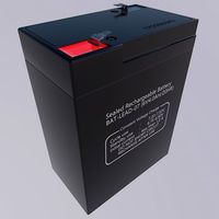
Lead-acid battery storage battery lithium battery
...ttery storage battery lithium battery
3dexport
1.lead-acid battery storage battery lithium battery 2.files include 3dmax obj fbx
3d_ocean
$7
Battery Model
...battery model
3docean
big battery car battery vehicle battery
car battery, big battery, vehicle battery.
3ddd
free

battery energier
...battery energier
3ddd
battery energier , батарейка
battery energier
3d_ocean
$1
Battery Model
...lack minus plus white yellow
this is battery model is about 1000 triangles. turntable preview is smoothed version of the battery.
3d_export
$10
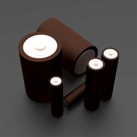
battery 18650
...battery 18650
3dexport
battery 18650
3d_export
free

battery
...battery
3dexport
Pack
3d_export
$5
pack
...pack
3dexport
low poly pack
archibase_planet
free

Packing
...packing
archibase planet
wrapping wrapper packing
packing 2 - 3d model (*.gsm+*.3ds) for interior 3d visualization.
archibase_planet
free

Packing
...packing
archibase planet
packaging wrapping packing
packing 3 - 3d model (*.gsm+*.3ds) for interior 3d visualization.
archibase_planet
free

Packing
...packing
archibase planet
wrapper packing packaging
packing 4 - 3d model (*.gsm+*.3ds) for interior 3d visualization.
archibase_planet
free

Packing
...packing
archibase planet
packaging wrapping packing
packing 5 - 3d model (*.gsm+*.3ds) for interior 3d visualization.
archibase_planet
free

Packing
...packing
archibase planet
packing packaging wrapper
packing 7 - 3d model (*.gsm+*.3ds) for interior 3d visualization.
3d_export
$7

Health Pack Armor Pack and Ammo Pack 3D Model
...pack 3d model
3dexport
health armor ammo pack check point game
health pack armor pack and ammo pack 3d model u2501 99166 3dexport
3d_ocean
$79
Turrets Pack - Tower Defense Pack
...be used in any sf type of game, especially in tower defense games. the pack includes: - flack cannon: 6239 polygons - chain gu...
3d_export
$7

arbalet pack
...arbalet pack
3dexport
arbalet pack
3d_export
$5

rocks pack
...rocks pack
3dexport
rocks pack