GrabCAD
OmniPlug
by GrabCAD
Last crawled date: 1 year, 11 months ago
School: Bergen County Academies, Hackensack. NJ
Instructor: Joseph DeFalco
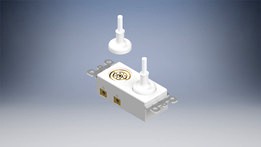
The current US outlet design is flawed. There are many safety and ease of use issues related to the current design. For instance, outlet prongs can still be touched when plugged in, presenting an electrical hazard and a safety hazard for people who may accidentally touch the prongs. In addition, the polarity of many plugs means that it can often only be plugged in one way. Additionally, alignment must be exactly correct in order to plug a cable in, meaning that it cannot be plugged in under low-light. My design is for a new type of outlet that attaches magnetically. The ring structure of the outlet means that a cable can be plugged in in any direction. Magnets in both the outlet and the plug means that the plug automatically aligns itself when placed close to the outlet. Additionally, the OmniPlug is far safer than US outlets. Because the outlet is completely inset from the surface, there is never exposed wire while power is flowing. In addition, my outlet contains extra contacts for presence detection. Wall power would only flow through the outlet when a plug is plugged in, which is enabled by relays and a 5V regulator placed inside the outlet, as seen in renderings and the components file. In the end, the OmniPlug solves the problems that plague our lives multiple times a day and is a much safer and easier to use alternative to traditional US wall outlets. As there are no commercial current solutions for magnetic outlets, this design is a new outlet concept, yet still another iteration on humanity’s progression through power attachment systems.
There are many different potential 3D printing technologies that may be used for the OmniPlug, ranging from FDM to SLA, SLS, and PolyJet. Each technology has its own unique advantages. SLA allows one to create high quality parts that are very accurate, while SLS is able to print without supports, as unsintered powder allows for the self-supporting of parts. In addition, PolyJet is able to handle a wide variety of materials. However, neither high precision nor self-supporting is necessary or worth the extra cost and hassle related to using these printing technologies. Instead, FDM is able to accomplish much of the same goals while still able to remain relatively inexpensive and available to the public. The OmniPlug can be printed using FDM technology, with a variety of materials. However, for increased temperature resistance, I would select ABS for the material, as safety in electrical boxes is of the utmost priority. The model is printable with support structures, as shown in the screenshots of a printing program. If necessary, supports can be made with water-soluble filament (PVA) for easy removal. A shortened version of the model has been printed, and surface features (contact points) were able to be printed.
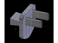
Many factors had to be taken into account when designing the OmniPlug. First, the dimensions were determined by the normal size for a power outlet/switch in an electrical box. A maximum depth was established based on the average size of an electrical box, with some space left to ensure easy wiring. This meant that the dimensions of the OmniPlug were approximately 33.4 mm x 106.2 mm. Next, the hole diameter had to be chosen. This dimension was also constrained by the size of the electrical box and outlet itself. To leave enough clearance on the sides of the power outlet so as not to look awkward, about a centimeter was subtracted off the width of the power outlet. Another design consideration came with ease of plugging in power cords. To ensure that a completely correct alignment was not necessary, a taper angle was added to the sides of each outlet. Afterwards, it was time to design the actual connection interface. Three contacts were necessary for the transmission of power: ground, hot, and neutral. In addition, another contact point was needed for the delivery of power only when a cable was connected. Safety was of the utmost importance here, so the ground connector was designed to always connect first and disconnect last. This was accomplished by making sure that the ground connection was shallower than the other contact points by 1 mm (much more than an FDM layer height). Contacts on the plug are intended to be spring-loaded, so the ground connector would be able to make contact first. In addition, the ground connection is wider by about 0.5 mm, allowing for more current to flow through ground than through the other contacts for increased safety in electrical failures. Wire width was also taken into consideration. The width of the smallest contact points are about 3 mm. This means that a 3 mm wide cable (9 AWG) would feasibly be able to supply power to each contact point. The most conservative estimates with a max of 80 degrees Celsius with copper wire allow 65 amps of current max to flow through the wire. This is plenty, as 120 V current would allow for 120 V * 86 A = 7800 W of current through the connector, which is far larger than the relay’s 2400 W rating. This means that each of the plugs can supply up to 2400 W, which is plenty for even the most intensive household appliances. To make sure that the design was easily 3D printable, as little overhang was added as possible. This is why the design of the OmniPlug is a basic box, allowing for ease of printing when compared to more complex shapes that are usually seen in other power outlets. However, only unavoidable overhangs were kept, like the metal connectors on each edge. In addition, layer heights were respected. The smallest z-height difference to be resolved is the ground connector, which is a height of about 1 mm. This allows for 3D printers to easily be able to print this model.
In the future, the OmniPlug may even be manufactured with FDM or other 3D printing technologies. 3D printing technologies have the large potential to advance the state of manufacturing, from the inception of a product idea all the way through production. First, 3D printing allows for fast, accurate, and inexpensive product prototypes. This allows for the prototyping process to be accelerated and less error prone, as errors can easily be noticed when an accurate prototype is available. Many large companies seem to think similarly, as their design labs usually contain 3D printers (Microsoft, Apple, etc.). Additionally, 3D Printing allows for complex manufacturing to be done easily. Some parts are simply too complex to be manufactured with traditional manufacturing techniques, like injection molding. For example, sets of interlocking 3D shapes that are able to rotate is extremely hard or even impossible to injection mold, but many 3D printing technologies are able to produce it. However, 3D printers are useful even if they don’t entirely replace the entire manufacturing chain. As traditional manufacturing techniques usually have large turnaround times, some timelines may be impossible to meet. However, a concept called bridge manufacturing allows both 3D printers and other manufacturing techniques to operate together. This concept calls for the manufacture of parts on a short time frame with 3D printers, with the transition to other manufacturing techniques once it is available. This allows tight deadlines to be met with ease, ensuring customer satisfaction. A recent example of this can be seen in Ultimaker, with their bridge manufacturing of improved reel holders on the Ultimaker 3. 3D printers allowed them to meet their product launch deadline. In the end, 3D printers are extremely useful throughout an entire product creation timeline, regardless of their level of involvement.
Instructor: Joseph DeFalco
The current US outlet design is flawed. There are many safety and ease of use issues related to the current design. For instance, outlet prongs can still be touched when plugged in, presenting an electrical hazard and a safety hazard for people who may accidentally touch the prongs. In addition, the polarity of many plugs means that it can often only be plugged in one way. Additionally, alignment must be exactly correct in order to plug a cable in, meaning that it cannot be plugged in under low-light. My design is for a new type of outlet that attaches magnetically. The ring structure of the outlet means that a cable can be plugged in in any direction. Magnets in both the outlet and the plug means that the plug automatically aligns itself when placed close to the outlet. Additionally, the OmniPlug is far safer than US outlets. Because the outlet is completely inset from the surface, there is never exposed wire while power is flowing. In addition, my outlet contains extra contacts for presence detection. Wall power would only flow through the outlet when a plug is plugged in, which is enabled by relays and a 5V regulator placed inside the outlet, as seen in renderings and the components file. In the end, the OmniPlug solves the problems that plague our lives multiple times a day and is a much safer and easier to use alternative to traditional US wall outlets. As there are no commercial current solutions for magnetic outlets, this design is a new outlet concept, yet still another iteration on humanity’s progression through power attachment systems.
There are many different potential 3D printing technologies that may be used for the OmniPlug, ranging from FDM to SLA, SLS, and PolyJet. Each technology has its own unique advantages. SLA allows one to create high quality parts that are very accurate, while SLS is able to print without supports, as unsintered powder allows for the self-supporting of parts. In addition, PolyJet is able to handle a wide variety of materials. However, neither high precision nor self-supporting is necessary or worth the extra cost and hassle related to using these printing technologies. Instead, FDM is able to accomplish much of the same goals while still able to remain relatively inexpensive and available to the public. The OmniPlug can be printed using FDM technology, with a variety of materials. However, for increased temperature resistance, I would select ABS for the material, as safety in electrical boxes is of the utmost priority. The model is printable with support structures, as shown in the screenshots of a printing program. If necessary, supports can be made with water-soluble filament (PVA) for easy removal. A shortened version of the model has been printed, and surface features (contact points) were able to be printed.
Many factors had to be taken into account when designing the OmniPlug. First, the dimensions were determined by the normal size for a power outlet/switch in an electrical box. A maximum depth was established based on the average size of an electrical box, with some space left to ensure easy wiring. This meant that the dimensions of the OmniPlug were approximately 33.4 mm x 106.2 mm. Next, the hole diameter had to be chosen. This dimension was also constrained by the size of the electrical box and outlet itself. To leave enough clearance on the sides of the power outlet so as not to look awkward, about a centimeter was subtracted off the width of the power outlet. Another design consideration came with ease of plugging in power cords. To ensure that a completely correct alignment was not necessary, a taper angle was added to the sides of each outlet. Afterwards, it was time to design the actual connection interface. Three contacts were necessary for the transmission of power: ground, hot, and neutral. In addition, another contact point was needed for the delivery of power only when a cable was connected. Safety was of the utmost importance here, so the ground connector was designed to always connect first and disconnect last. This was accomplished by making sure that the ground connection was shallower than the other contact points by 1 mm (much more than an FDM layer height). Contacts on the plug are intended to be spring-loaded, so the ground connector would be able to make contact first. In addition, the ground connection is wider by about 0.5 mm, allowing for more current to flow through ground than through the other contacts for increased safety in electrical failures. Wire width was also taken into consideration. The width of the smallest contact points are about 3 mm. This means that a 3 mm wide cable (9 AWG) would feasibly be able to supply power to each contact point. The most conservative estimates with a max of 80 degrees Celsius with copper wire allow 65 amps of current max to flow through the wire. This is plenty, as 120 V current would allow for 120 V * 86 A = 7800 W of current through the connector, which is far larger than the relay’s 2400 W rating. This means that each of the plugs can supply up to 2400 W, which is plenty for even the most intensive household appliances. To make sure that the design was easily 3D printable, as little overhang was added as possible. This is why the design of the OmniPlug is a basic box, allowing for ease of printing when compared to more complex shapes that are usually seen in other power outlets. However, only unavoidable overhangs were kept, like the metal connectors on each edge. In addition, layer heights were respected. The smallest z-height difference to be resolved is the ground connector, which is a height of about 1 mm. This allows for 3D printers to easily be able to print this model.
In the future, the OmniPlug may even be manufactured with FDM or other 3D printing technologies. 3D printing technologies have the large potential to advance the state of manufacturing, from the inception of a product idea all the way through production. First, 3D printing allows for fast, accurate, and inexpensive product prototypes. This allows for the prototyping process to be accelerated and less error prone, as errors can easily be noticed when an accurate prototype is available. Many large companies seem to think similarly, as their design labs usually contain 3D printers (Microsoft, Apple, etc.). Additionally, 3D Printing allows for complex manufacturing to be done easily. Some parts are simply too complex to be manufactured with traditional manufacturing techniques, like injection molding. For example, sets of interlocking 3D shapes that are able to rotate is extremely hard or even impossible to injection mold, but many 3D printing technologies are able to produce it. However, 3D printers are useful even if they don’t entirely replace the entire manufacturing chain. As traditional manufacturing techniques usually have large turnaround times, some timelines may be impossible to meet. However, a concept called bridge manufacturing allows both 3D printers and other manufacturing techniques to operate together. This concept calls for the manufacture of parts on a short time frame with 3D printers, with the transition to other manufacturing techniques once it is available. This allows tight deadlines to be met with ease, ensuring customer satisfaction. A recent example of this can be seen in Ultimaker, with their bridge manufacturing of improved reel holders on the Ultimaker 3. 3D printers allowed them to meet their product launch deadline. In the end, 3D printers are extremely useful throughout an entire product creation timeline, regardless of their level of involvement.
Similar models
3d_ocean
$5

Double Schuko Socket
...nt electricity energy europe germany outlet plug power safety socket schuko socket voltage wall socket
an old style schuko socket
grabcad
free

2023 FRC Charged Up Playing Field - 3D Printable
...ned to be printed with saf technology however the shape of the object lends itself well to being printed with fdm/fff technology.
cg_trader
$4

Electrical plug
...ric electroplexy electricity cord cabel euro europe standard three three contact grounding universal electronics other power cord
cg_trader
$2

Surge Protector with Plug
...equipment voltage cable switch connector socket energy indicator electrical outlet electrical switch household other power switch
cg_trader
$2

Multi Plug socket
...al equipment socket energy electronics switch electrical outlet outlet power connector interior industrial architectural lighting
cg_trader
$5
Ac Plug
...n plastic electric cable energy connector cee schuko europlug plug ac wire typef black electronics other switch electrical outlet
cg_trader
free

UK double electric socket with plug
...c switch cable voltage power current connector electrical electricity electrical outlet energy architectural fixture power switch
3d_ocean
$3
Schuko Socket
...nector power power point safety socket schuko socket wall socket
a schuko socket like the ones used in germany. colored old white
thingiverse
free

UK Electrical Outlet Key by msayre
...nd pin socket to open the gate.
run a rubber band through the eyelet of this key to tie it to your european style power cables.
thingiverse
free
Outlet safety plug by kkendall
...outlet safety plug by kkendall
thingiverse
child safety plug for us power outlets