Thingiverse

NeoDue Part 1 - Duet Wifi for GRR Neo by Mechanotronikum
by Thingiverse
Last crawled date: 3 years, 1 month ago
Since my Neo did benefit a lot from Thingiverse (special thanks to Kakadu for his E3D upgrade and his table stiffener, and for stueckl for his inductive Z endstop); I wanted to give something back, so here is part one of my "NeoDue" upgrade, where I have replaced the old Printrboard with a Duet Wifi (and a display, but that is part 2).
To change the electronics board, you need
a Duet Wifi board
one of each of the three 3D parts printed out on your Neo
two M3 x 20 mm (or longer) screws to mount the board holder to the fan outlet
two M3 nuts to mount the fan again
five Ø2.9...3 mm x 6mm screws for plastic (for the cover part and the Duet Wifi)
Hints for mounting:
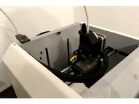
remove board cooling fan and old Printrboard electronics
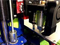
change the cable paths as shown in the pictures (you will need to make the wires of the Z motor, the Z sensor and the main power cable ca. 10 cm longer; the others do fit)
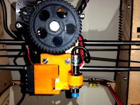
turn the extruder motor as shown in the picture so that the connector faces up
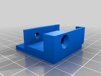
assemble board holder (halter_leiterplatte.stl), faceplate (blende.stl) and cover piece (schutzhaube.stl) using the short screws
if you like to add some extra safety against oil dripping onto the board whenever you oil your linear bearings, use some tape to cover the gap between the board holder and the cover piece.
now mount the assembly to the fan outlet hole using the two M3 screws.
mount fan onto protruding screws on backside of fan outlet hole and secure with M3 nuts. Caution: blowing direction = towards z axis, i.e. the opposite direction as before! The ribs on the board holder will direct the airflow so that the steppers get the cooling they need. Works fine on my machine so far.
cutout left plastic cover of Neo to fit the faceplate
now mount board
don't forget to secure the wires again
For setting up of the board please refer to Duet documentation - just some short remarks:
I run the Duet with 19.5V as the original (I did change however the power supply to a 230W one when I changed the print head, so I cannot guarantee if the original Neo supply will provide the power needed)
the connectors of the steppers and the endstops can be left as they are; but you might want to switch to an NPN endstop if you currently use the inductive endstop from stueckl. (A PNP endstop requires quite a bit of additional electronics: first, you need to add a separate voltage stabilizer for the sensor, e.g. for 9V. Then add a 2,2k resistor between Duet Z endstop input pin and ground pin, and add a second resistor between sensor output and Duet Z endstop input pin, thus creating a voltage divider which needs to provide 3V at the endstop input pin if the sensor is active. The resistance of that second resistor needs to be calculated accordingly. An NPN sensor is much easier to connect, just add a BAT43 diode as mentioned in the Duet Wiki.)
the steppers work fine on my machine if I let them run with 500...600mA.
To change the electronics board, you need
a Duet Wifi board
one of each of the three 3D parts printed out on your Neo
two M3 x 20 mm (or longer) screws to mount the board holder to the fan outlet
two M3 nuts to mount the fan again
five Ø2.9...3 mm x 6mm screws for plastic (for the cover part and the Duet Wifi)
Hints for mounting:
remove board cooling fan and old Printrboard electronics
change the cable paths as shown in the pictures (you will need to make the wires of the Z motor, the Z sensor and the main power cable ca. 10 cm longer; the others do fit)
turn the extruder motor as shown in the picture so that the connector faces up
assemble board holder (halter_leiterplatte.stl), faceplate (blende.stl) and cover piece (schutzhaube.stl) using the short screws
if you like to add some extra safety against oil dripping onto the board whenever you oil your linear bearings, use some tape to cover the gap between the board holder and the cover piece.
now mount the assembly to the fan outlet hole using the two M3 screws.
mount fan onto protruding screws on backside of fan outlet hole and secure with M3 nuts. Caution: blowing direction = towards z axis, i.e. the opposite direction as before! The ribs on the board holder will direct the airflow so that the steppers get the cooling they need. Works fine on my machine so far.
cutout left plastic cover of Neo to fit the faceplate
now mount board
don't forget to secure the wires again
For setting up of the board please refer to Duet documentation - just some short remarks:
I run the Duet with 19.5V as the original (I did change however the power supply to a 230W one when I changed the print head, so I cannot guarantee if the original Neo supply will provide the power needed)
the connectors of the steppers and the endstops can be left as they are; but you might want to switch to an NPN endstop if you currently use the inductive endstop from stueckl. (A PNP endstop requires quite a bit of additional electronics: first, you need to add a separate voltage stabilizer for the sensor, e.g. for 9V. Then add a 2,2k resistor between Duet Z endstop input pin and ground pin, and add a second resistor between sensor output and Duet Z endstop input pin, thus creating a voltage divider which needs to provide 3V at the endstop input pin if the sensor is active. The resistance of that second resistor needs to be calculated accordingly. An NPN sensor is much easier to connect, just add a BAT43 diode as mentioned in the Duet Wiki.)
the steppers work fine on my machine if I let them run with 500...600mA.
Similar models
thingiverse
free

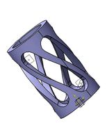
Duet Wifi Turbo Case by cyllenius
.... m3 x 4 screws were used to jon the feet to the fan (the feet don't need nuts).
feel free to remix and modify to your needs.
thingiverse
free

Z-Endstop Reprap Neo by stueckl
...sor
mount the assembly at the hohles
shorten the wire, crimp the connector and connect it.
test it
close all an be happy!
thingiverse
free

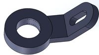
Inductive z-endstop German Reprap Neo by stueckl
...ttached.
connect the endstop to the board.
!test it!
adjust it from the front side. use the two screws.
close the back cover.
thingiverse
free

Ender 3 Duet 2 Wifi Case by Tramziller
...rews that also hold the fan in place.
case itself is mounted with up to 6 hammer nuts (i have used m5 hammer nuts with m5 screws)
thingiverse
free
Ender 3 Filament sensor assembly (using orginal Z endstop)
...ed as filament sensor pin for skr v1.3 board)
holes need slight enhancement (3mm drill for z axis screw, 2.5 mm for board screws)
thingiverse
free

Duet Wifi plus Duex expansion mount, vented by destuiper
...d fit just fine for boards and fan. sd card, usb port, reset and erase buttons plus leds can be accessed and seen from the front.
thingiverse
free
Proximity Sensor Mount - Auto Bed Levelling by MightyLAD
...r.
proximity sensor i used is - lj12a3-4-z/bx (inductive npn - so no resistors needed on ramps - ace!)
the mount hole is dia 12mm
thingiverse
free

Duet 2 Wifi Enclosure by ImAThingsGuy
...s is one of my earlier designs for my duet wifi, it needs 5 m3 heat press inserts and whatever screws you need for a 30x30 mm fan
thingiverse
free
Autolevel with Inductive Sensor P3 Steel by ksevin
...checkout my nozzle fan duct: https://www.thingiverse.com/thing:2771787
bowden upgrade: https://www.thingiverse.com/thing:2766928
thingiverse
free

HyperCube Evolution max z endstop by alexflin
...ws for each endstop.
idea is to adjust the flag height with the vertical screw and then locking it down with the horizontal screw
Mechanotronikum
thingiverse
free
Bondtech BMG direct drive extruder for GRR Neo by Mechanotronikum
...dapter.
at least on my printer, this upgrade did wonders to print quality relative to the original bowden design. happy printing!
thingiverse
free
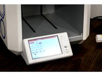
NeoDue Part 2 - 5" PanelDue Display for GRR Neo by Mechanotronikum
...duet logo can be used to reset the display if needed. the usb port for updating the display firmware is accessible from the side.
Grr
3dfindit
free

GRR
...grr
3dfind.it
catalog: festo
3dfindit
free

GRR
...grr
3dfind.it
catalog: festo
thingiverse
free

GRR-RIPPER Heel
...ush block.
these are disposable parts; print your own replacement!
this variant has a couple of holes for a jig fitting i needed.
thingiverse
free

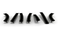
E3D FAN GRR X400 Bauteilkühler by Kernfusion
...r x400 bauteilkühler by kernfusion
thingiverse
this is a remix of https://www.thingiverse.com/thing:1591912
a little bit shorter
thingiverse
free

GRR NEO Extruder tool by NitroXpress
...ool to de-tension the pressure roll of the german reprap neo filament extruder.
much easier to thread the filament.
have fun...
thingiverse
free

LCD display cover for GRR Protos V3 by kloberujo
...b of the lcd-display of german reprap's protos v3 - it just looks nicer like that. if precisly printed fits without fixtures.
thingiverse
free

Messuhrhalter für der GRR Neo by Helisinus
...ötigt.
english:
dial indicator for grr neo.
you need to extend the dial indicator and you need 6 x neodymium magnets 5mm x 2mm
thingiverse
free
Bondtech BMG direct drive extruder for GRR Neo by Mechanotronikum
...dapter.
at least on my printer, this upgrade did wonders to print quality relative to the original bowden design. happy printing!
thingiverse
free

Microjig GRR-RIPPER Gravity Heel Kit
...1.0.0.4a004c4dcjk0si
all in, parts should be less than $3.00
when fully retracted, the heel is about 1mm above the surface plane.
Duet
turbosquid
$10

Duet
... available on turbo squid, the world's leading provider of digital 3d models for visualization, films, television, and games.
3ddd
$1
Orgadoor / Duet
...door , дверь
фабрика: orgadoor
коллекция: organic
модель: duet
сайт: www.orgadoor.com.ua
turbosquid
$47

Duet rally car
...uid
royalty free 3d model duet rally car for download as fbx on turbosquid: 3d models for games, architecture, videos. (1501869)
turbosquid
$39

Duet solid white
...d
royalty free 3d model duet solid white for download as fbx on turbosquid: 3d models for games, architecture, videos. (1236356)
turbosquid
free

Bench with a table Duet
...del bench with a table duet for download as max, obj, and fbx on turbosquid: 3d models for games, architecture, videos. (1655855)
turbosquid
$13

chandelier Lussole Loft Duet
...
royalty free 3d model lussole loft duet for download as 3ds on turbosquid: 3d models for games, architecture, videos. (1180567)
turbosquid
$60

Duet classic car silver
...lty free 3d model duet classic car silver for download as fbx on turbosquid: 3d models for games, architecture, videos. (1489252)
turbosquid
$50

Duet classic car black
...alty free 3d model duet classic car black for download as fbx on turbosquid: 3d models for games, architecture, videos. (1490723)
turbosquid
$49

Duet car white and red
...alty free 3d model duet car white and red for download as fbx on turbosquid: 3d models for games, architecture, videos. (1486820)
turbosquid
$30

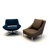
Bloom Upholstered Duet Lounge Chair
...model bloom upholstered duet lounge chair for download as max on turbosquid: 3d models for games, architecture, videos. (1503906)
Neo
design_connected
$18

Neos
...neos
designconnected
wilkhahn neos computer generated 3d model. designed by wiege.
design_connected
$7

Neos
...neos
designconnected
gruppo feg neos computer generated 3d model. designed by nunziati, matteo.
turbosquid
$7

NEO
...
royalty free 3d model neo for download as max, obj, and fbx on turbosquid: 3d models for games, architecture, videos. (1219070)
turbosquid
$30

Neo
... available on turbo squid, the world's leading provider of digital 3d models for visualization, films, television, and games.
3ddd
$1
Neo chair
...neo chair
3ddd
кресло
http://www.ufficidea.com/schedaprodotto_2720_seduta-direzionale-neo-chair.php
3ddd
$1
Riho NEO
... угловая
угловая акриловая ванна neo 140л.
фабрика изготовитель - riho
страна производитель: чехия
размер: 140 x 140 см
3ddd
$1
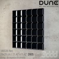
DUNE - NEO
... панель
186536 neo
29x29 cm./ 11,42”x11,42” d935
8 mm. de espesor/thicknesshttp://www.dune.es
3ddd
$1
Neo
...neo
3ddd
3d max 2009,vray 1.5 sp2+fbx
3ddd
$1
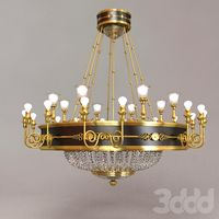
Russion neo classic
...russion neo classic
3ddd
lustra russion neo classic
3d_export
$7
neo matrix 1999
...neo matrix 1999
3dexport
neo matrix 1999 под печать
Wifi
turbosquid
$1

Wifi Icon
...rbosquid
royalty free 3d model wifi icon for download as fbx on turbosquid: 3d models for games, architecture, videos. (1546436)
turbosquid
$10

WiFi Camera
... available on turbo squid, the world's leading provider of digital 3d models for visualization, films, television, and games.
design_connected
$4
Wifi Coffee Table
...offee table
designconnected
liv'it wifi coffee table coffee tables computer generated 3d model. designed by stefan schöning.
turbosquid
$2
Wifi Signal Booster
...yalty free 3d model wifi signal booster for download as blend on turbosquid: 3d models for games, architecture, videos. (1281888)
turbosquid
$15

IOT Wifi Switch
...odel iot wifi switch for download as obj, fbx, blend, and dae on turbosquid: 3d models for games, architecture, videos. (1510115)
3d_export
$12

IPod WiFi 3D Model
...ipod wifi 3d model
3dexport
ipod wi-fi
ipod wifi 3d model fau 71186 3dexport
turbosquid
$59

iPad Air WiFi
... available on turbo squid, the world's leading provider of digital 3d models for visualization, films, television, and games.
turbosquid
$5
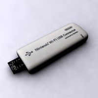
Nintendo USB WIFI
... available on turbo squid, the world's leading provider of digital 3d models for visualization, films, television, and games.
turbosquid
$2

Wireless WiFi Router
...eless wifi router for download as blend, x, fbx, stl, and obj on turbosquid: 3d models for games, architecture, videos. (1682399)
turbosquid
$7

Wifi internet logo
...nternet logo for download as max, ige, obj, fbx, dwg, and stl on turbosquid: 3d models for games, architecture, videos. (1369275)
Part
3d_export
$5
Parts
...parts
3dexport
parts
3d_export
$5
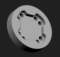
Part
...part
3dexport
part
3d_export
$5

Part
...part
3dexport
machine part
3d_export
$65

Part
...part
3dexport
simple rendering of the scene file
3d_export
$65

Part
...part
3dexport
simple rendering of the scene file
3d_export
$30

fan part
...fan part
3dexport
this is a part of fan of pedastal
3d_export
$10
machine parts
...machine parts
3dexport
3d part modeling work ,contact for 3d work
turbosquid
$59

Mechanical Part
...id
royalty free 3d model mechanical part for download as c4d on turbosquid: 3d models for games, architecture, videos. (1410833)
turbosquid
$17
Road parts
...bosquid
royalty free 3d model road parts for download as 3ds on turbosquid: 3d models for games, architecture, videos. (1192967)
turbosquid
$9

Cutter Parts
...squid
royalty free 3d model cutter parts for download as stl on turbosquid: 3d models for games, architecture, videos. (1220010)
1
turbosquid
$69
armchairs(1)(1)
... available on turbo squid, the world's leading provider of digital 3d models for visualization, films, television, and games.
turbosquid
$15
ring 1+1
... available on turbo squid, the world's leading provider of digital 3d models for visualization, films, television, and games.
turbosquid
$10
chair(1)(1)
... available on turbo squid, the world's leading provider of digital 3d models for visualization, films, television, and games.
turbosquid
$8

Chair(1)(1)
... available on turbo squid, the world's leading provider of digital 3d models for visualization, films, television, and games.
turbosquid
$2

RING 1(1)
... available on turbo squid, the world's leading provider of digital 3d models for visualization, films, television, and games.
turbosquid
$1

Table 1(1)
... available on turbo squid, the world's leading provider of digital 3d models for visualization, films, television, and games.
turbosquid
$1
house 1(1)
... available on turbo squid, the world's leading provider of digital 3d models for visualization, films, television, and games.
turbosquid
$59

Formula 1(1)
...lty free 3d model formula 1 for download as max, fbx, and obj on turbosquid: 3d models for games, architecture, videos. (1567088)
design_connected
$11
No 1
...no 1
designconnected
sibast no 1 computer generated 3d model. designed by sibast, helge.
turbosquid
$2
desert house(1)(1)
...3d model desert house(1)(1) for download as 3ds, max, and obj on turbosquid: 3d models for games, architecture, videos. (1055095)