Thingiverse
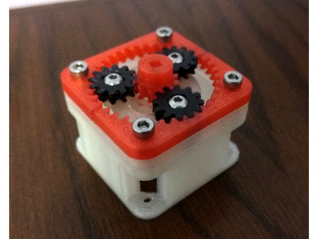
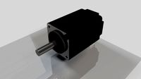
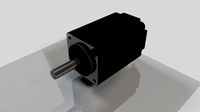
NEMA-17 1:4 step-up gearbox for remote direct drive by dalia5
by Thingiverse
Last crawled date: 2 years, 11 months ago
Introduction
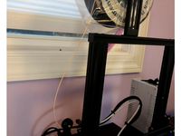
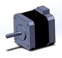
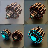
Remote direct drive extruders like the Flex3Drive (and its clone the Zesty Nimble) use large reduction gearing at the toolhead side to keep high torque from the extruder hob off the flex shaft. This has a side effect of seriously limiting the speed/acceleration of retraction and Linear Advance/Pressure Advance moves. For me, this pretty much defeated the purpose of switching to direct drive. So, I designed and built this gearbox to bring the net reduction down to 1:10. This has made it possible to do 1 mm retractions in under 50 ms (32 mm/s, 2000 mm/s² acceleration), and to use a very low smooth_time of 10 ms with Klipper's Pressure Advance, for accurate extrusion at high speed and acceleration.
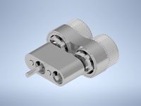
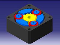
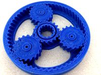
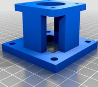
The gearbox design is modular, consisting of an extender bracket to get the gears to the end of the motor shaft and to allow assembly on the motor in-place, a shaft coupler that engages the planetary carrier with a square drive, the gears themselves including a split ring gear, and spacers which can be used if needed.
The motor end of the extruder's flex drive shaft inserts directly into the sun gear. The square hole in the sun gear is nominally 3.2 by 3.2 mm, and is designed for the flex shaft that ships with the Flex3Drive G5. Before printing and assembling the rest of the gearbox, make sure your shaft fits the sun gear. It should be easy to modify if it doesn't.
There are two versions of the planetary gears drive. One is designed for press fit with 683ZZ bearings for smooth motion and distribution of force across the gear, but requires more hardware for assembly. The other has 2 mm holes in the gears, for use with metal shaft or perhaps even snippets of filament. I recommend the version with bearings, as it should run smoother and not develop slop as it wears, but the no-hardware version is nice if you want to test before buying components, and may be viable for long-term use with TPU gears.
I'm using this on an Ender 3 with the 22 mm extruder motor shaft length and D flat cut in the shaft, but installation should be possible on any NEMA 17 motor with a 5 mm shaft diameter, using appropriate spacers and positioning of the coupler.
Non-printed parts needed for assembly
Shaft pinch coupler:
1x M3 nut
1x 8mm M3 bolt
Mount to motor:
4x 8mm M3 bolts (possibly longer depending on bracket and spacers)
Main assembly:
4x M3 nuts
4x 20mm M3 bolts (possibly longer if using spacers)
Planetary gear set (only if building the version with bearings):
3x 683ZZ bearings
3x 8mm M3 bolts, button head preferred
3x M3 nuts
3x M3 washers (can be printed if you don't have any)
Print material
Gears: PETG or TPU is ideal. If using TPU, it should be a hard variety, and printed with proper wall settings so that the part comes out solid. PLA works but is not recommended; it will be very noisy to operate.
Structural parts: PETG or PLA.
ABS should not be used for any parts unless you have a compatible (non-oil-based) lubricant.
Lubrication
Gears should be lubricated before attempting to operate. Any automotive grease is good; red high-temperature STP was what I had on hand. Operate the gears by hand, or with a drill or rotary tool, before installing to ensure they can turn freely.
Recommended print settings
Gears: 0.10-0.12 mm layers, 3 walls, recommend reducing to 0.35 mm outer wall to allow a contiguous second wall in teeth. Use 5 walls for the no-bearings version of the planet gears to get a solid part. This is especially important if printing in TPU.
Carrier and coupler: 4 walls, 0.20 mm layers.
Extender: 3 walls, supports, 0.20-0.25 mm layers.
Spacers (if needed): 3 walls, 0.20-0.25 mm layers.
Infill percentage can be low (e.g. 10%) for all parts since the strength comes from walls not infill.
All parts require fairly tight dimensional accuracy, and are designed for 0.1 mm clearances (most places, in both directions, so 0.2 mm total). If your printer is not well tuned, you may need to apply some horizontal offsets to get parts that fit together. I recommend 0.4 mm nozzle/line width (except as mentioned above) but nothing in the design depends on single-line walls, so other sizes close to 0.4 are probably okay to use.
Planetary gears assembly
Bearings version
Mount bearings to the carrier with washers so that the outer race does not rub on the carrier body when it turns.
Press 2 planet gears just slightly onto their bearings.
Hold sun gear in place.
Fit third planet gear to sun gear and press it onto its bearing enough to hold it.
Press all three planet gears the rest of the way onto their bearings.
No-bearings version
Cut 3 10mm shafts from filament or 1.75-2mm diameter metal rod.
Ensure shafts fit in upper and lower carrier holes. If they don't, drill the holes slightly by hand or with a power tool, but be careful not to make a hole all the way through.
Insert one shaft into each hole of lower carrier.
Lubricate the shafts.
Sit 2 planet gears on the end of their shafts.
Hold sun gear in place.
Fit third planet gear to sun gear and place it on the end of its shaft.
Press all three planet gears the rest of the way down.
Clip upper carrier to lower carrier, fitting the shafts to their corresponding holes.
After assembling the planetary gears, lubricate them well.
Installation
Press fit 4 M3 nuts into the extender bracket.
Attach the exender bracket to the motor where it's mounted using 4 M3 screws.
Press fit 1 M3 nut into the motor shaft coupler and place an M3 screw through it, but don't tighten yet.
Press the coupler into the square on the planetary gear assembly's carrier.
Slide the coupler onto the motor shaft.
Place half of the ring gear on top of the bracket and hold it in place temporarily with screws.
Line up the planetary gear assembly to the ring gear to determine the height to mount the motor shaft coupler at. This should put the top of the coupler's square output drive roughly 1mm below the top of the extender bracker. (If the shaft extends above that such that it would interfere with the sun gear, you'll need to add spacers above or below the bracket.) Tighten the coupler down in place using a hex key to reach it through the openings in the bracket.
Remove the temporary screws holding half of the ring gear and install the full ring gear, placing a spacer and the part provided with your extruder to hold the flex cable housing on top, and fasten the whole assembly with M3 screws.
After ensuring the gears turn correctly without the extruder connected, press the square end of the flex shaft into the sun gear.
If you need to remove/disassemble the gearbox, it can be separated from the coupler to lift it off by applying pressure to the carrier from below, or using needle nosed pliers to grab the carrier and pull it up. Pulling by the gears is not recommended and will probably make the assembly fall apart.
Videos
Remote direct drive extruders like the Flex3Drive (and its clone the Zesty Nimble) use large reduction gearing at the toolhead side to keep high torque from the extruder hob off the flex shaft. This has a side effect of seriously limiting the speed/acceleration of retraction and Linear Advance/Pressure Advance moves. For me, this pretty much defeated the purpose of switching to direct drive. So, I designed and built this gearbox to bring the net reduction down to 1:10. This has made it possible to do 1 mm retractions in under 50 ms (32 mm/s, 2000 mm/s² acceleration), and to use a very low smooth_time of 10 ms with Klipper's Pressure Advance, for accurate extrusion at high speed and acceleration.
The gearbox design is modular, consisting of an extender bracket to get the gears to the end of the motor shaft and to allow assembly on the motor in-place, a shaft coupler that engages the planetary carrier with a square drive, the gears themselves including a split ring gear, and spacers which can be used if needed.
The motor end of the extruder's flex drive shaft inserts directly into the sun gear. The square hole in the sun gear is nominally 3.2 by 3.2 mm, and is designed for the flex shaft that ships with the Flex3Drive G5. Before printing and assembling the rest of the gearbox, make sure your shaft fits the sun gear. It should be easy to modify if it doesn't.
There are two versions of the planetary gears drive. One is designed for press fit with 683ZZ bearings for smooth motion and distribution of force across the gear, but requires more hardware for assembly. The other has 2 mm holes in the gears, for use with metal shaft or perhaps even snippets of filament. I recommend the version with bearings, as it should run smoother and not develop slop as it wears, but the no-hardware version is nice if you want to test before buying components, and may be viable for long-term use with TPU gears.
I'm using this on an Ender 3 with the 22 mm extruder motor shaft length and D flat cut in the shaft, but installation should be possible on any NEMA 17 motor with a 5 mm shaft diameter, using appropriate spacers and positioning of the coupler.
Non-printed parts needed for assembly
Shaft pinch coupler:
1x M3 nut
1x 8mm M3 bolt
Mount to motor:
4x 8mm M3 bolts (possibly longer depending on bracket and spacers)
Main assembly:
4x M3 nuts
4x 20mm M3 bolts (possibly longer if using spacers)
Planetary gear set (only if building the version with bearings):
3x 683ZZ bearings
3x 8mm M3 bolts, button head preferred
3x M3 nuts
3x M3 washers (can be printed if you don't have any)
Print material
Gears: PETG or TPU is ideal. If using TPU, it should be a hard variety, and printed with proper wall settings so that the part comes out solid. PLA works but is not recommended; it will be very noisy to operate.
Structural parts: PETG or PLA.
ABS should not be used for any parts unless you have a compatible (non-oil-based) lubricant.
Lubrication
Gears should be lubricated before attempting to operate. Any automotive grease is good; red high-temperature STP was what I had on hand. Operate the gears by hand, or with a drill or rotary tool, before installing to ensure they can turn freely.
Recommended print settings
Gears: 0.10-0.12 mm layers, 3 walls, recommend reducing to 0.35 mm outer wall to allow a contiguous second wall in teeth. Use 5 walls for the no-bearings version of the planet gears to get a solid part. This is especially important if printing in TPU.
Carrier and coupler: 4 walls, 0.20 mm layers.
Extender: 3 walls, supports, 0.20-0.25 mm layers.
Spacers (if needed): 3 walls, 0.20-0.25 mm layers.
Infill percentage can be low (e.g. 10%) for all parts since the strength comes from walls not infill.
All parts require fairly tight dimensional accuracy, and are designed for 0.1 mm clearances (most places, in both directions, so 0.2 mm total). If your printer is not well tuned, you may need to apply some horizontal offsets to get parts that fit together. I recommend 0.4 mm nozzle/line width (except as mentioned above) but nothing in the design depends on single-line walls, so other sizes close to 0.4 are probably okay to use.
Planetary gears assembly
Bearings version
Mount bearings to the carrier with washers so that the outer race does not rub on the carrier body when it turns.
Press 2 planet gears just slightly onto their bearings.
Hold sun gear in place.
Fit third planet gear to sun gear and press it onto its bearing enough to hold it.
Press all three planet gears the rest of the way onto their bearings.
No-bearings version
Cut 3 10mm shafts from filament or 1.75-2mm diameter metal rod.
Ensure shafts fit in upper and lower carrier holes. If they don't, drill the holes slightly by hand or with a power tool, but be careful not to make a hole all the way through.
Insert one shaft into each hole of lower carrier.
Lubricate the shafts.
Sit 2 planet gears on the end of their shafts.
Hold sun gear in place.
Fit third planet gear to sun gear and place it on the end of its shaft.
Press all three planet gears the rest of the way down.
Clip upper carrier to lower carrier, fitting the shafts to their corresponding holes.
After assembling the planetary gears, lubricate them well.
Installation
Press fit 4 M3 nuts into the extender bracket.
Attach the exender bracket to the motor where it's mounted using 4 M3 screws.
Press fit 1 M3 nut into the motor shaft coupler and place an M3 screw through it, but don't tighten yet.
Press the coupler into the square on the planetary gear assembly's carrier.
Slide the coupler onto the motor shaft.
Place half of the ring gear on top of the bracket and hold it in place temporarily with screws.
Line up the planetary gear assembly to the ring gear to determine the height to mount the motor shaft coupler at. This should put the top of the coupler's square output drive roughly 1mm below the top of the extender bracker. (If the shaft extends above that such that it would interfere with the sun gear, you'll need to add spacers above or below the bracket.) Tighten the coupler down in place using a hex key to reach it through the openings in the bracket.
Remove the temporary screws holding half of the ring gear and install the full ring gear, placing a spacer and the part provided with your extruder to hold the flex cable housing on top, and fasten the whole assembly with M3 screws.
After ensuring the gears turn correctly without the extruder connected, press the square end of the flex shaft into the sun gear.
If you need to remove/disassemble the gearbox, it can be separated from the coupler to lift it off by applying pressure to the carrier from below, or using needle nosed pliers to grab the carrier and pull it up. Pulling by the gears is not recommended and will probably make the assembly fall apart.
Videos
Similar models
grabcad
free

5:1 planetary gearbox with nema 17
...ma 17
grabcad
5:1 planetary gearbox with nema 17
with m3 brass insert nut
support bearings in carrier, planet gear and sun gear.
grabcad
free

Planetary Gearbox Assembly
... parts- sun gear shaft, planet gear carrier and it's part.
*total weight= 1kg (density=1000kg/m3).
*designed on catia v5 r21.
grabcad
free

Planetary Gearbox #347 | design with ajay |
... ratios. they are widely used in a variety of applications, including automobiles, industrial equipment, robotics, and aerospace.
grabcad
free

Planet carrier
...planet carrier is used in planetary gear assembly for power transmission it encloses the sun gear and planet gear in the assembly
thingiverse
free
planetary gearbox smasher thing
...em and install them onto the shafts of the 2 gearboxes.
10) put the other 2 drive gears in place and install the drive gear case.
thingiverse
free

NEMA23 planetary gearbox with an encoder mount, 3.333 gear reduction ratio by ErikRudec
...ication is essential - you should not run the gears dry or the planets will bind to the carrier. apply a lot of lubricant grease.
thingiverse
free
NEMA 23 Planetary gearbox reducer, 1:3.333 ratio by ErikRudec
...ication is essential - you should not run the gears dry or the planets will bind to the carrier. apply a lot of lubricant grease.
grabcad
free

Planetary Gear Box
...el of planetary gearbox
- input shaft connected with the sun gear
- output shaft connected with the carrier
- ring gear is fixed.
thingiverse
free

3:1 Planetary Geared Extruder
...f bearings
added pinion gear for smaller motor without recess or full length d drive to cater for extended d drine on the pinion.
thingiverse
free
Planetary gear system by dan241297
...cy of different 3d printers the gears may be a tight or loose fit.
the two halves of the y-carrier screw together with m3 screws.
Gearbox
3d_export
$7

planetary gearbox
...planetary gearbox
3dexport
planetary gearbox
3d_export
$5
transmission gearbox
...transmission gearbox
3dexport
transmission gearbox
3d_export
$30
differential gearbox
...differential gearbox
3dexport
3d model of a differential gearbox.<br>modeled in solidworks.<br>rendered in keyshot.
turbosquid
$4

planetary gearbox
...royalty free 3d model planetary gearbox for download as blend on turbosquid: 3d models for games, architecture, videos. (1423384)
3d_export
$5
three stage planetary gearbox
...three stage planetary gearbox
3dexport
three stage planetary gearbox
turbosquid
$31
2 speed reducer Gearbox
... dual stage helical speed reducer gearbox for download as iam on turbosquid: 3d models for games, architecture, videos. (1650029)
3d_export
$15
automatic processing line for gearbox pump body
...automatic processing line for gearbox pump body
3dexport
automatic processing line for gearbox pump body
3d_export
$1000

Automobile Manual Transmission mechanism Gearbox 3D Model
...ox 3d model
3dexport
transmission gearbox
automobile manual transmission mechanism gearbox 3d model daveterminator 24996 3dexport
3d_export
$8
tool replacement gearbox
...tool replacement gearbox
3dexport
eccentric lifting mechanism, you can process according to available drawings.
3d_export
$7
milling machine spindle drive diagram - milling gearbox
... n = 4500 rin / min; maximum power p = 7.5 kw. bt40 spindle, like welcome to download to learn. there are igs format files in it.
Nema
3d_export
$5
Electric Motor Nema 17
...electric motor nema 17
3dexport
40mm stepper motor nema 17 1.5a (17hs4401) motor 4-wire for 3d printer
turbosquid
$3
Nema 17
...rbosquid
royalty free 3d model nitro engine for download as on turbosquid: 3d models for games, architecture, videos. (1449252)
turbosquid
$1
Nema 17 Stepper motor
... available on turbo squid, the world's leading provider of digital 3d models for visualization, films, television, and games.
turbosquid
$1
Nema 17 Stepper Motor 59Nm
... available on turbo squid, the world's leading provider of digital 3d models for visualization, films, television, and games.
turbosquid
$3
Simple model of Nema 8 stepper motor
...del of nema 8 stepper motor for download as ipt, obj, and stl on turbosquid: 3d models for games, architecture, videos. (1543132)
3d_export
$5

simple model of nema 17 stepper motor
...ort
simple model, useful to prototype robots, 3d printers and other electronic diy projects<br>step and .ipt file included
3d_export
$5
simple model of nema 8 stepper motor
...robots, 3d printers and other electronic diy projects<br>current model: 20bygh33-0604a<br>step and .ipt file included
3ddd
free

Larte Luce
...class="star five "></div></div></li><li><img src="http://b.3ddd.ru/media/cache/sky_user_avatar_comment/avatar/users/117489.jpg" alt="ci-nema" width="35" height="35" class="img"><div class="name"><a href="/users/ci-nemaquot;>ci-nema</a></div><div class="raiting"><div class="star five "></div></div></li></ul><div class="more"><a href="/3dmodels/show/larte_luce/voted">еще</a></div></div><div class="number" rating="30" count="6"...
thingiverse
free

Nema 14 to Nema 17 Adapter by lukepat
...nema 14 to nema 17 adapter by lukepat
thingiverse
created a adapter for nema 14 to nema 17 mount.
thingiverse
free
Distance Nema 17 and Nema 23 by Krzysztof_Handtke
...distance nema 17 and nema 23 by krzysztof_handtke
thingiverse
distance to nema motors to build a cnc milling machine.
Remote
archibase_planet
free

Remote
...remote
archibase planet
tv remote remote controller remote
remote - 3d model for interior 3d visualization.
archibase_planet
free

Remote
...e
archibase planet
remote control remote controller remote
remote n140512 - 3d model (*.gsm+*.3ds) for interior 3d visualization.
turbosquid
$1

Remote
...
turbosquid
royalty free 3d model remote for download as obj on turbosquid: 3d models for games, architecture, videos. (1487515)
3d_export
$5

Tv Remote
...tv remote
3dexport
tv remote
3d_ocean
$7

Remote controller
... control switcher tv remote
remote controller for tv, sound systems etc easy to edit textures photo real rendered with mental ray
turbosquid
$39

remote
...free 3d model remote for download as obj, fbx, blend, and dae on turbosquid: 3d models for games, architecture, videos. (1387531)
turbosquid
$5

remote
...free 3d model remote for download as 3ds, obj, fbx, and blend on turbosquid: 3d models for games, architecture, videos. (1401849)
archive3d
free

Remote 3D Model
...l
archive3d
tv remote remote controller remote
remote - 3d model for interior 3d visualization.
turbosquid
$11
Remote
... available on turbo squid, the world's leading provider of digital 3d models for visualization, films, television, and games.
turbosquid
$10

remote
... available on turbo squid, the world's leading provider of digital 3d models for visualization, films, television, and games.
Direct
design_connected
free
Compas Direction
...compas direction
designconnected
free 3d model of compas direction by vitra designed by prouvé, jean.
design_connected
$18

Direction Pivotant
...direction pivotant
designconnected
vitra direction pivotant computer generated 3d model. designed by prouvé, jean.
turbosquid
$6
not direct the front
...oyalty free 3d model not direct the front for download as max on turbosquid: 3d models for games, architecture, videos. (1213034)
turbosquid
$10

Rails Direct
... available on turbo squid, the world's leading provider of digital 3d models for visualization, films, television, and games.
3d_export
$5

Picto toilet directions
...lude 3d files next to rhino6: x3dv, step, igus, obj and stl. double-sided, flipping changes the gender directions to the toilets.
3ddd
$1
fauteuli direction
...d
chair , vitra , fauteuli
fauteuli vitra chair
design_connected
$18

Fauteuil Direction, 1951
...fauteuil direction, 1951
designconnected
vitra fauteuil direction, 1951 computer generated 3d model. designed by prouvé, jean.
3d_export
$5
Directional tactile 3D Model
...tactile 3d model
3dexport
directional tactile braille tile flooring interior
directional tactile 3d model renob000 71068 3dexport
turbosquid
$26

Radio direction finder A
...ty free 3d model radio direction finder a for download as fbx on turbosquid: 3d models for games, architecture, videos. (1212490)
turbosquid
$7

Wooden direction signage
...ty free 3d model wooden direction signage for download as max on turbosquid: 3d models for games, architecture, videos. (1453747)
17
3d_export
$6
rocks 17
...rocks 17
3dexport
rocks 3d model 17
3ddd
$1

PLANTS 17
...plants 17
3ddd
цветок , горшок
plants 17,, pots in diameter 100,80,60,40cm,,, enjoy
3d_export
$6
tap-17
...tap-17
3dexport
3d_export
$6

set-17
...set-17
3dexport
3d_export
$27

C-17 Globemaster
...c-17 globemaster
3dexport
c-17 globemaster
3ddd
free

Renault FT-17
...renault ft-17
3ddd
ft-17 , renault , танк
turbosquid
$40
cottage 17
...bosquid
royalty free 3d model cottage 17 for download as max on turbosquid: 3d models for games, architecture, videos. (1377003)
turbosquid
$30

Apartment 17
...squid
royalty free 3d model apartment 17 for download as max on turbosquid: 3d models for games, architecture, videos. (1432680)
turbosquid
$10

Surfboard 17
...squid
royalty free 3d model surfboard 17 for download as max on turbosquid: 3d models for games, architecture, videos. (1375686)
turbosquid
$7
Rock 17
...turbosquid
royalty free 3d model rock 17 for download as obj on turbosquid: 3d models for games, architecture, videos. (1486522)
Drive
turbosquid
$90
Drive
...turbosquid
royalty free 3d model drive for download as blend on turbosquid: 3d models for games, architecture, videos. (1654393)
3d_export
$10

cycloidal drive
...cycloidal drive
3dexport
cycloidal drive
3d_ocean
$5
Flash Drive
...h drive included : – materials – scene ( lighs / room ) – .c4d + .obj for any questions please feel free to contact me thank you.
3d_ocean
$5

Usb drive
...s shaders and a lighting setup. it also has a small animation of it going in and out. i saved it out as both a .blend file and...
3d_ocean
$5

Pen Drive
...est computer drive game model good low poly new pen pen drive textured unwrapped uv very low poly
a very beautiful low poly model
3d_ocean
$10
External hard drive
... is a detailed model of a trekstor external hard drive. you can easily modify the label on the top. simply edit the text objects.
turbosquid
$60

Star Drive
...squid
royalty free 3d model star drive for download as blend on turbosquid: 3d models for games, architecture, videos. (1254314)
turbosquid
$50

Star Drive
...squid
royalty free 3d model star drive for download as blend on turbosquid: 3d models for games, architecture, videos. (1263524)
turbosquid
$45
Star Drive
...squid
royalty free 3d model star drive for download as blend on turbosquid: 3d models for games, architecture, videos. (1287060)
turbosquid
$40
Star Drive
...squid
royalty free 3d model star drive for download as blend on turbosquid: 3d models for games, architecture, videos. (1261902)
Step
3ddd
free
Pro Seda Step by Step
... by step
3ddd
step , proseda , кушетка
pro seda
design_connected
$9

Step
...step
designconnected
porada step coffee tables computer generated 3d model. designed by tarciso colzani.
turbosquid
$49

Steps
... available on turbo squid, the world's leading provider of digital 3d models for visualization, films, television, and games.
turbosquid
$30
step
... available on turbo squid, the world's leading provider of digital 3d models for visualization, films, television, and games.
turbosquid
$11

Step
... available on turbo squid, the world's leading provider of digital 3d models for visualization, films, television, and games.
3d_export
$20
Folding steps step stool 3D Model
...tool stepstool steps ladder tool tools garage workshop shed basement
folding steps step stool 3d model pixelblock 43270 3dexport
3d_export
$5

Glass steps
...glass steps
3dexport
well, just glass steps
3ddd
$1

Lago Steps
...lago steps
3ddd
lago
lago steps chair.
3d_export
$10
steps with cocrete
...steps with cocrete
3dexport
design steps for the architecture engineering purpose
archibase_planet
free

Rack step
...rack step
archibase planet
rack step rack gym
rack step - 3d model (*.gsm+*.3ds) for exterior 3d visualization.
4
turbosquid
$9

Office Chair 4-4
... available on turbo squid, the world's leading provider of digital 3d models for visualization, films, television, and games.
3d_export
$5

doors- 4
...doors- 4
3dexport
doors 4
3d_export
$5
hinge 4
...hinge 4
3dexport
hinge 4
3ddd
$1

Штора №4
...штора №4
3ddd
штора №4
3d_export
free
playstation 4
...playstation 4
3dexport
playstation 4
turbosquid
$1
re 4-4 electric locomotive
... free 3d model re 4 4 electric locomotive for download as obj on turbosquid: 3d models for games, architecture, videos. (1707845)
3ddd
$1

nexus 4
...nexus 4
3ddd
lg , телефон
nexus 4
3ddd
$1
4 Poufs
...4 poufs
3ddd
пуф
4 soft poufs
turbosquid
$12

Calligraphic Digit 4 Number 4
...hic digit 4 number 4 for download as max, obj, fbx, and blend on turbosquid: 3d models for games, architecture, videos. (1389332)
3ddd
$1
Dauphin 4+
...dauphin 4+
3ddd
кресло
dauphin 4+ конференц кресло
1
turbosquid
$69

armchairs(1)(1)
... available on turbo squid, the world's leading provider of digital 3d models for visualization, films, television, and games.
turbosquid
$15
ring 1+1
... available on turbo squid, the world's leading provider of digital 3d models for visualization, films, television, and games.
turbosquid
$10
chair(1)(1)
... available on turbo squid, the world's leading provider of digital 3d models for visualization, films, television, and games.
turbosquid
$8

Chair(1)(1)
... available on turbo squid, the world's leading provider of digital 3d models for visualization, films, television, and games.
turbosquid
$2

RING 1(1)
... available on turbo squid, the world's leading provider of digital 3d models for visualization, films, television, and games.
turbosquid
$1

Table 1(1)
... available on turbo squid, the world's leading provider of digital 3d models for visualization, films, television, and games.
turbosquid
$1
house 1(1)
... available on turbo squid, the world's leading provider of digital 3d models for visualization, films, television, and games.
turbosquid
$59

Formula 1(1)
...lty free 3d model formula 1 for download as max, fbx, and obj on turbosquid: 3d models for games, architecture, videos. (1567088)
design_connected
$11
No 1
...no 1
designconnected
sibast no 1 computer generated 3d model. designed by sibast, helge.
turbosquid
$2
desert house(1)(1)
...3d model desert house(1)(1) for download as 3ds, max, and obj on turbosquid: 3d models for games, architecture, videos. (1055095)