GrabCAD
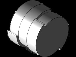
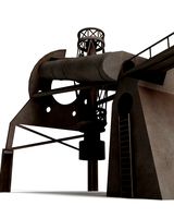
NASA RASSOR Bucket
by GrabCAD
Last crawled date: 1 year, 11 months ago
Attached Files:
- Bucket.step - The primary design as a compounded object.
- fills.step - It contains the estimation of volume of sand in each bucket drum, according to the method described below.
- Bucket.stl - STL file of the primary design.
Design Introduction:
The bucket is built in 3 sections/drums, with 2 scoops per drum. Each drum has a width of 118mm and consists of 4 sheets, bent along the path of two full revolution spirals, at 180 degrees to each other, with the thicker sheets covering a little more than half of each path, that will be exposed to the outside environment. There are 4 plates for covering and separating the drums. The outer plates are 1.5mm thick, while inner plates are 1.5mm thick on the outside and 0.5mm thick on the inside, where it only serves as a drum separating medium, and not much strength is required. Following are the specifications :-
- Cross-section of scoop = 35mm*118mm.
- Fill ratio = 58.5% (worst case)
- Total model weight = 4.5kg. (Assuming all sheets are made of Aluminium, and blades are made of Titanium.) Some weight will be added when connections are made (welding/brazing).
- Enclosing cylinder dimensions: Diameter = 450mm, Length = 360mm.
Method for estimating fill ratio:
The regolith retention by the drum is highly dependent on its flowability. If the regolith can flow easily, then it will be easier to take it in, but it will also be easy to let it slip out. If the regolith is too sticky/muddy, it will be difficult to take it in, but once it reaches the inside of the drum, it will be easier to hold it inside. As 20 rpm is a decently low speed, it is assumed that the regolith has enough time to flow to the inside of the drum. So, only the loss of regolith, that was brought inside in the drum in the previous scoop, is considered. This loss will be maximum for high flowability regolith. Hence, regolith is considered almost as a fluid (with a fixed angle of friction).
Based on this, static situation was considered at different angular positions, between the states when blades are vertically separated, and when they are horizontally separated. Angle of friction has been taken as 30 degrees, which is typical for sand. The last state (when blades are at same horizontal level) was found to be the worst position, with minimum volume of regolith retained. This volume was multiplied by 3 and divided by volume of bounding cylinder (pi*0.225^2*0.36) which gave a value of 58.43%. Fill ratio can be higher or lower(less likely) in dynamic condition. The fill volume estimates for single drum are shown in "fills.step" for reference, at angular positions of 30, 45, 60, 75 and 90 degree tilts from the first state. Obviously, no regolith can be as free flowing as has been assumed, and therefore, actual fill ratio is expected to be higher (near about 60%).
Construction:
- The bucket is made completely from 1.5mm and 0.5mm strips and sheets (except for the blade). The material is assumed as Aluminium, as it can be connected by brazing easily.
- The strips are to be bent into spirals (6 spirals/ bucket). Dimensions of strips are 700mm*118mm*1.5mm (6nos.) and 490mm*118mm*0.5mm (6nos.). A good way in which this can be done, is by making spiral sheet cutouts, and clamping the strips onto these cutouts at the ends, and then tempering the strips (under gas flame) to relieve stresses.
- The profiles of the 4 plates are to be cut from the sheets, as per the design, by laser cutting.
- The different parts can be connected by brazing. (Resistance welding small brackets to both the strip and the plate, can be used to strengthen the joint between them, but it will add some weight.)
- The connections (braze welds) should be made in a stacking manner: End Plate --> Spiral Bent Strips --> Middle Plate --> Spiral Bent Strips --> Second Middle Plate --> Spiral Bent Strips --> Second End Plate. In order to make the last braze weld possible, height of the last pair of strips will have to be 1mm more than the other ones, and the second end plate will have to be slotted, to make the strips below it accessible for brazing from the outside.
- The blades will have to be 3-D printed or casted using a 3-D printed pattern, and can be screwed/resistance welded to the bent strips before making the above connections.
Notes on design:
- There is a trade-off between scoop height and fill factor, when the growth of the spiral path is changed. 35mm height of scoop was chosen as decent compromise between the two. In the referred research paper, it is mentioned that rocks upto 5cm can be picked up. In case it is absolutely necessary to incorporated this capability, the scoop height will have to be increased to 50mm. This reduces the fill factor to 51.35% when calculated by the same method as above. The mass of model also reduces to 4.32kg.
- Full separation between the drums is probably not needed, but the complex flow of sand between the drums can't be simulated, hence, it has been given in the design.
- Based on a quick simulation, it was found that the bulging of the end plate due to hydrostatic-like pressure from inside sand was negligible (less than 1 mm when assumed to be 100% filled). Also, the polar MOI is relatively high. Hence, there was no need felt for a stiffner along the axis of the bucket.
Similar models
grabcad
free

Rassor Bucket Drum Design improvement
...dimensions of one scoop 85.5×44 mm (inner). digging speed approx. 15 mm/s. intended volume of regolith captured inside 22 liters.
grabcad
free

NASA (RASSOR) Bucket Drum Design Challenge with Design VPR 21
...ely for blades and bucket
7. inside section view while filling bucket
8. section view of one from 16 modified 623zz ball bearings
grabcad
free

NASA RASSOR Bucket Drum
...enario.
i think this design would work and would not be complicated to fabricate, as the shapes and structures are kept simple.
grabcad
free

NASA RASSOR "Chum Bucket"
... be cnc milled. these parts can then be welded together to create one solid part.
4. the design meets all dimension requirements.
grabcad
free

RASSOR bucket drum with shutter mechanism
...oughly 80%) filled. a filling ratio of 100% is not possible because the shutter plates need a certain degree of movement freedom.
grabcad
free

93% Fill Bucket Drum
...achieve the desired 17.6 liter capacity. this bucket drum design can be scaled to fit other robotic regolith collecting vehicles.
grabcad
free

NASA RASSOR Challenge Entry
...that could approximate the fill. a jpeg of the dimensions of this estimation is attached as well as the mathematical calculation.
grabcad
free

bucket drum NASA challenge
...ter: 450 mm
the average captured volume of regolith: 20 liters
materials used:
scoop blades: titanium
rest of the drum: aluminum
grabcad
free

Spiral Screw Bucket Drum
...the drum. working: the bucket drum works in a similar way to the archimedes screw transporting water. during loading,...
grabcad
free

Excavator
...ed: 30.88 liters
fill ratio: 80%
the fill ratio of the barrel is estimated, i believe that it should be at least 80% fill ratio.
Rassor
grabcad
free

RASSOR
...rassor
grabcad
just tried to design rassor
hope you like it :)
grabcad
free

Rassor
...s effesien used for mining in outer space, the system used is the mortar mixing system. this drum rassor uses horizontal rotation
grabcad
free

Rassor
...rassor
grabcad
modeling of rassor drums for the collection of extraterrestrial soil. rhinoceros, file stl and renderings
grabcad
free

Rassor Bucket
...rassor bucket
grabcad
nasa rassor challenge
grabcad
free

RASSOR
... (rassor) with major highlight is the excavation blade is a angle of 30 degree. the software used in particle simulation is edem
grabcad
free

RASSOR
...rassor
grabcad
this is a very simple and innovative plan
grabcad
free

RASSOR Regolith Miner
...rassor regolith miner
grabcad
designed for the nasa rassor bucket challenge
grabcad
free

rassor de Alonso
...rassor de alonso
grabcad
eta es una pala para el sistema rassor
grabcad
free

RASSOR Scoop Drum
...rassor scoop drum
grabcad
stl / jpeg / txt file submission for nasa rassor scoop challenge
grabcad
free

NASA RASSOR BUCKET
... is a design for nasa rassor bucket. the total weight of the bucket is 4.94 kg. for unloading rotate the bucket counterclockwise.
Nasa
turbosquid
$49
Nasa Marscopter
...id
royalty free 3d model nasa marscopter for download as max on turbosquid: 3d models for games, architecture, videos. (1323349)
turbosquid
$500
NASA Crawler
... available on turbo squid, the world's leading provider of digital 3d models for visualization, films, television, and games.
turbosquid
$5

Nasa Rocket
... available on turbo squid, the world's leading provider of digital 3d models for visualization, films, television, and games.
turbosquid
$1
NASA Spool.max
... available on turbo squid, the world's leading provider of digital 3d models for visualization, films, television, and games.
3d_export
$15

US NASA 3D Model
...us nasa 3d model
3dexport
spaceship ship nasa battle blender
us nasa 3d model antonielfelain 96625 3dexport
turbosquid
$99
NASA MIT Wing
...oyalty free 3d model nasa mit wing for download as ma and max on turbosquid: 3d models for games, architecture, videos. (1510099)
turbosquid
$29
NASA Electronic Telescope
... available on turbo squid, the world's leading provider of digital 3d models for visualization, films, television, and games.
turbosquid
$6

Real flag NASA
... available on turbo squid, the world's leading provider of digital 3d models for visualization, films, television, and games.
3d_export
$41
NASA FAST Satellite 3D Model
...odel
3dexport
nasa space satellite earth aurora sensor panel solar orbit
nasa fast satellite 3d model visualmotion 20244 3dexport
3d_export
$20

22k photorealistic earth - nasa
...tures directly from nasa.<br>nasa solar system bundle coming soon!<br>contact info@teichmanmedia.eu for all iquiries.
Bucket
archibase_planet
free

Bucket
...bucket
archibase planet
pail bucket tub
bucket - 3d model for interior 3d visualization.
3d_ocean
$5
Bucket
...bucket
3docean
bucket cleaning galvanized gavanised stainless steel zinc zinc coated
a galvanized bucket
turbosquid
free
Bucket bucket With Water
... available on turbo squid, the world's leading provider of digital 3d models for visualization, films, television, and games.
archibase_planet
free
Bucket
...bucket
archibase planet
bucket pail
bucket n250308 - 3d model (*.gsm+*.3ds) for interior 3d visualization.
archibase_planet
free
Bucket
...bucket
archibase planet
tub bucket pail
bucket - 3d model (*.gsm+*.3ds) for interior 3d visualization.
archibase_planet
free
Bucket
...bucket
archibase planet
bucket pail bin
bucket n280612 - 3d model (*.gsm+*.3ds) for interior 3d visualization.
archibase_planet
free
Bucket
...bucket
archibase planet
pail bucket tub
bucket 2 - 3d model (*.gsm+*.3ds) for interior 3d visualization.
archibase_planet
free

Bucket
...bucket
archibase planet
fire fighting equipment dip-bucket
bucket - 3d model (*.gsm+*.3ds) for interior 3d visualization.
3d_export
$5
bucket
...bucket
3dexport
scratched galvanized bucket. fbx, obj, blend, and testura formats
3ddd
$1
Wooden bucket
...wooden bucket
3ddd
wooden bucket , ведро
wooden bucket