Thingiverse
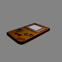
Nantendo LED matrix console game by loska
by Thingiverse
Last crawled date: 3 years ago
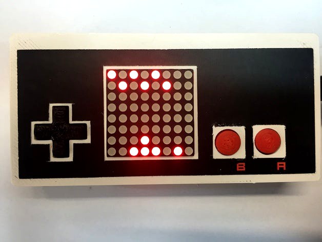
Nintendo NES controller inspired hand held game console with 8x8 LED matrix display!
Update April 2017
New firmware integrates Doodle Jump with the rest of the games, also adds 'Flashy Bird' and sound effects in the main file.
I had a batch PCBs made professionally. They are available for AUD$10 + postage, here: https://www.ebay.com.au/itm/Nantendo-PCB-for-Hand-Held-8x8-Arduino-Game/254313782931
I will also consider putting together a kit of all non-printed parts - send a message if interested.
**
This console is based on an Arduino Nano and a 1.2" 8x8 LED matrix display with a HT16K33 driver. Both of these are available cheaply from eBay, Total build cost should be under $20 (assuming you can make your own PCB).
The 'Nantendo' firmware has Pong, Space Invaders, Snake, Breakout and a Car driving game as well as a slightly weird game called 'Tedshow'.
The firmware is adapted from here:http://letsmakerobots.com/node/44115
The main differences are that this design uses a different display driver and uses buttons rather than a potentiometer for left-right control.
Alternatively, there is an adapted version of 'DoodleJump' based on this:https://github.com/brnunes/Arduino-Doodle-Jump
There is another adaptation of all the games with sound and including Doodle Jump here, however it is not quite as stable:https://hackaday.io/project/12310-diy-led-8x8-matrix-game-console-64bit
I am planning to merge the sound effects and other games back in in the future.
Instructions:
Print parts according to the Bill of Materials
Print the label onto adhesive material and cut it out with a scalpel
Make the PCB from the Eagle files
Assemble the PCB
Copy the Arduino libraries from the libraries folder in 'Arduino_Nantendo.zip' into your own Arduino libraries folder (usually, Documents / Arduino / libraries)
Load the firmware using the Arduino host software and a USB mini cable
Assemble the housing
Get playing!
PCB assembly notes:
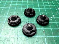
If your 8x8 display comes with right angle header connectors, remove them by cutting the pins, pulling off the plastic part then carefully desoldering each pin - see photo
Use a 4-way straight header to connect the display to the PCB.
Optinally, use 1 or 2 printed spacers and M2 screws to steady the top of the display. I just screwed into the PCB then cut the screws flush at the back since they are behind the battery holder. Alternatively you could use thin double sided tape between the boards.
Bend the pins on the micro slide switch to 90 degrees before inserting
Bend the pins on the 4xAAA battery holder flat and cut them short to fit within the large PCB pads; align the mounting holes but attach the holder with double sided foam tape. Note you may wish to file the solder pads and M2 screws to make this fit flush.
Update April 2017
New firmware integrates Doodle Jump with the rest of the games, also adds 'Flashy Bird' and sound effects in the main file.
I had a batch PCBs made professionally. They are available for AUD$10 + postage, here: https://www.ebay.com.au/itm/Nantendo-PCB-for-Hand-Held-8x8-Arduino-Game/254313782931
I will also consider putting together a kit of all non-printed parts - send a message if interested.
**
This console is based on an Arduino Nano and a 1.2" 8x8 LED matrix display with a HT16K33 driver. Both of these are available cheaply from eBay, Total build cost should be under $20 (assuming you can make your own PCB).
The 'Nantendo' firmware has Pong, Space Invaders, Snake, Breakout and a Car driving game as well as a slightly weird game called 'Tedshow'.
The firmware is adapted from here:http://letsmakerobots.com/node/44115
The main differences are that this design uses a different display driver and uses buttons rather than a potentiometer for left-right control.
Alternatively, there is an adapted version of 'DoodleJump' based on this:https://github.com/brnunes/Arduino-Doodle-Jump
There is another adaptation of all the games with sound and including Doodle Jump here, however it is not quite as stable:https://hackaday.io/project/12310-diy-led-8x8-matrix-game-console-64bit
I am planning to merge the sound effects and other games back in in the future.
Instructions:
Print parts according to the Bill of Materials
Print the label onto adhesive material and cut it out with a scalpel
Make the PCB from the Eagle files
Assemble the PCB
Copy the Arduino libraries from the libraries folder in 'Arduino_Nantendo.zip' into your own Arduino libraries folder (usually, Documents / Arduino / libraries)
Load the firmware using the Arduino host software and a USB mini cable
Assemble the housing
Get playing!
PCB assembly notes:
If your 8x8 display comes with right angle header connectors, remove them by cutting the pins, pulling off the plastic part then carefully desoldering each pin - see photo
Use a 4-way straight header to connect the display to the PCB.
Optinally, use 1 or 2 printed spacers and M2 screws to steady the top of the display. I just screwed into the PCB then cut the screws flush at the back since they are behind the battery holder. Alternatively you could use thin double sided tape between the boards.
Bend the pins on the micro slide switch to 90 degrees before inserting
Bend the pins on the 4xAAA battery holder flat and cut them short to fit within the large PCB pads; align the mounting holes but attach the holder with double sided foam tape. Note you may wish to file the solder pads and M2 screws to make this fit flush.
Similar models
3dwarehouse
free

Arduino - Display module of noise level
...ainbowduino and 8x8 matrix and speakers #arduino_uno #display #grove #lcd #led_bar #rainbowduino #sensor #shield #sound #speakers
thingiverse
free

LED Matrix Display 8x24 by isaac879
...t the text to be displayed.
arduino nano code: https://github.com/isaac879/led-matrix-display
video: https://youtu.be/auglqu87xkq
thingiverse
free

Stand for 8x8 led matrixes by oevsegneev
...es controlled by max7219 and arduino/rpi/nodemcu.
how to use it with nodemcu:http://robotclass.ru/articles/nodemcu-iot-led-matrix
thingiverse
free

8x8 LED Matrix Holder by pattonsrobots
...res 4-6 4-40 sized screws and nuts. i have a video on connecting the 8x8 led matrix here on youtube. https://youtu.be/phvzbgwdm_u
grabcad
free

Led Matrix Display 8x8 Max7219 Arduino
...mon market modules.
useful to design other stuff without wasting time in calculations.
module size: 50x52mm
display size: 32x32mm
thingiverse
free

Arduino Micro Holder by zcsaale
...
thingiverse
small holder for an arduino micro without headers. no screws, completely held in by friction. designed in sketchup.
grabcad
free

LED Display 8x8
...led display 8x8
grabcad
a led display with reverse smd led´s in a matrix of 8x8 led´s and driver ic.
thingiverse
free
Modular display for 4 matrix 8x8, rotary encoder, led for arduino by OfficialProjecto
...ith 4 8x8 led matrices, a rotary encoder and supports up to 4 led lights. the display is modular, you can create a custom attack.
grabcad
free

LED MATRIX 8x8 DISPLAY R/G
...led matrix 8x8 display r/g
grabcad
big led matrix 8x8 display red and or green dots
dimentions 51x51 mm, type common cathode
grabcad
free

Led Matrix Display FYM-15881
...led matrix display fym-15881
grabcad
led matrix display fym-15881 (8x8 led) (38mm x 38mm)
Loska
thingiverse
free
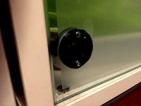
Replacement hinge plate for Ikea glass door cabinet by loska
...everal of these over the years and they work well.
note that the original silver cover cap push fits over this part, as pictured.
thingiverse
free
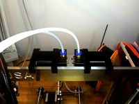
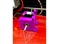
Bowden extruder hanger for 6mm frame by loska
...pper wires and keep things neat.
the files here are for a left hand extruder; simply flip along the x axis for a right hand set.
thingiverse
free
Beyblade ball bearing performance tip by loska
...o included, to adapt for other clearances or ball sizes. this file also includes the 3 other tip designs from the remixed design.
thingiverse
free

A4 Mini Vacuum Table by loska
...mounting points are set at 160mm spacing to suit my t-slot table. adjust as needed.
ideally, lightly skim the bed after mounting.
thingiverse
free
Air powered bottle water pistol by loska
...with the tubing.
fill the bottle 2/3 with water, screw in tight, pump up through the tyre valve to about 60psi and get squirting!
thingiverse
free
PCB milling alignment pin grid for 3018 CNC
...pins should be used for alignment. many thanks to loska and kudos for his awesome...
thingiverse
free

CNC frame rock tumbler by loska
...a one of the mounting screws.
fit the rest of the frame plus the cover plate with 4 x small self tapping screws before operating.
thingiverse
free
Aluminium Prusa i3 X-Carriage for Chimera and 18mm Sensor by loska
... screw holes in the chimera body through to the front, so i can adjust the nozzle heights easily by just taking the 30mm fan off.
thingiverse
free
Bowden extruder hanger for 8mm frame by Wast3D
...hanger for 8mm frame by wast3d thingiverse i remixed loska#39;s version of the motor hanger for a 6mm frame...
Matrix
3ddd
$1

Matrix
...matrix
3ddd
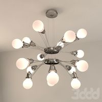
lumina , matrix
модель светильника matrix
3ddd
$1
Lumina Matrix
... lumina , matrix
светильник matrix doppia от фабрики lumina
3ddd
$1
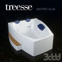
MATRIX SLIM
...reesse , ванна , джакузи
treesse - matrix sleem
3ddd
$1

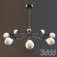
Люстра Lumina - Matrix
...люстра lumina - matrix
3ddd
lumina , matrix
люстра lumina - matrix
3ddd
$1

mebel MATRIX
...mebel matrix
3ddd
коллекция мебели matrix, линейка мебельной фабрики bfm. производство польша.
3ddd
$1
Светильник Lumina Matrix
...к lumina matrix
3ddd
lumina , matrix
светильник lumina matrix - максимальная детализация
design_connected
free
Matrix Terra
...matrix terra
designconnected
free 3d model of matrix terra by lumina italia designed by kaufman, yaacov.
design_connected
$11
Matrix 8
...matrix 8
designconnected
lumina italia matrix 8 computer generated 3d model. designed by kaufman, yaacov.
3ddd
$1
MATRIX by MAURO FADEL
...iproducts.com/it/prodotti/96755/matrix-poltroncina-a-slitta-con-braccioli-matrix-poltroncina-a-slitta-la-cividina.html#
3ddd
$1
APU Matrix Robot
...apu matrix robot
3ddd
робот
apu matrix robot
Console
archibase_planet
free
Console
...console
archibase planet
console console-table desk
console n200212 - 3d model (*.3ds) for interior 3d visualization.
3d_export
free
console
...console
3dexport
console
archibase_planet
free
Console
...console
archibase planet
console console-table rack
console n261111 - 3d model (*.gsm+*.3ds) for interior 3d visualization.
archibase_planet
free
Console
...console
archibase planet
console console-table desk table
console n210113 - 3d model (*.3ds) for interior 3d visualization.
3ddd
$1
console
...console
3ddd
консоль
console
3ddd
$1

console
...console
3ddd
консоль
console
3ddd
free

console
...console
3ddd
консоль
console
3ddd
$1
console
...console
3ddd
кронштейн
classic console
3ddd
$1
console
...console
3ddd
кронштейн
classic console
3ddd
$1
CONSOLE
...console
3ddd
тумба
console table
Led
3d_export
$5
led
...led
3dexport
the led is cut with all the parts.
3ddd
$1
Monacor / PARL56DMX / LED-320RGBW / LED-345RGBW / LED-300RGB
... прожектор
http://www.monacor.dk/
parl56dmx
led-320rgbw
led-345rgbw
led-300rgb
turbosquid
$10
LED
...led
turbosquid
free 3d model led for download as blend on turbosquid: 3d models for games, architecture, videos. (1691856)
3d_export
$5

led lamp
...led lamp
3dexport
led lamp, brightness animation
3ddd
free
leds-c4
...leds-c4
3ddd
leds-c4
современный торшер
3ddd
free
leds-c4
...leds-c4
3ddd
leds-c4
настольный лампа
turbosquid
$19

LED
... available on turbo squid, the world's leading provider of digital 3d models for visualization, films, television, and games.
turbosquid
$12
Led
... available on turbo squid, the world's leading provider of digital 3d models for visualization, films, television, and games.
turbosquid
free

LED
... available on turbo squid, the world's leading provider of digital 3d models for visualization, films, television, and games.
turbosquid
free
LED
... available on turbo squid, the world's leading provider of digital 3d models for visualization, films, television, and games.
Game
3d_ocean
$4
Games
...games
3docean
3d games models real stick
3d, models, sports, games , trail
turbosquid
$5

Games
...s
turbosquid
royalty free 3d model games for download as skp on turbosquid: 3d models for games, architecture, videos. (1612115)
turbosquid
$65

game
... available on turbo squid, the world's leading provider of digital 3d models for visualization, films, television, and games.
turbosquid
$25

Game
... available on turbo squid, the world's leading provider of digital 3d models for visualization, films, television, and games.
turbosquid
$10

Game
... available on turbo squid, the world's leading provider of digital 3d models for visualization, films, television, and games.
turbosquid
$5
Game
...bosquid
royalty free 3d model gameplay for download as blend on turbosquid: 3d models for games, architecture, videos. (1274934)
3d_ocean
$7

game place
...game place
3docean
children game game park game place kids play luna park play
for kids game place
3d_export
$14

game character
...game character
3dexport
game character use for gaming
turbosquid
$20

Game Ready Car For Video Games
...e 3d model game ready car for video games for download as fbx on turbosquid: 3d models for games, architecture, videos. (1499375)
3d_ocean
$5
Game fence
...game fence
3docean
fence game
a high quality game ready fence.