Thingiverse
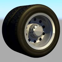
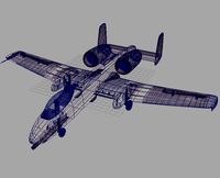
MyRCCar 1/10 MTC Rigid Axles: 4 different axle wides, 8 different CVDs, wheelbases from 290 to 330mm and universal shafts by dlb5
by Thingiverse
Last crawled date: 3 years ago
After listening to the crowd I had to do this last work about RC car styles.
To examine and download the parts, please visit this publication
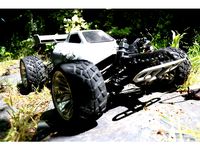
When I designed MTC Chassis I knew I wanted to be able to build an "hybrid", a rc car with independent suspension in the front and rigid axle in the back, but I have gone a little more far...
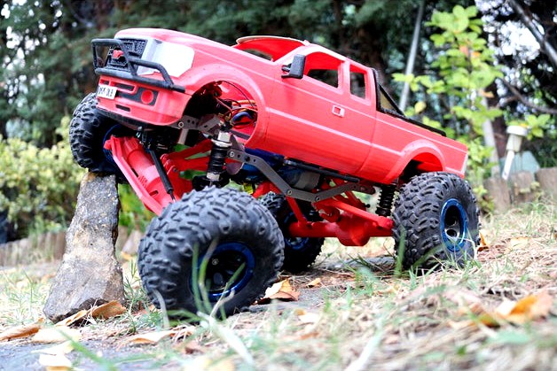
Now you can reuse some of the original MTC Chassis printed parts to build a Monster Truck / Crawler with rigid axles, 4 link suspension system and universal shafts, I think they call it like that to double cardan variable length transmissions.
Hey! No video by now :( Anyway suscribe or visit my Youtube Channel to see previous videos from the MTC Chassis and the Pickup
I'm a little tired right now to write up very specific instructions, maybe by now this publication is just for "experts" like those who can recieve instructions directly from the shapes of the design and logic patterns.
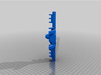
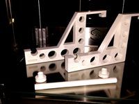
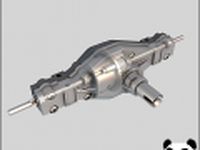
The Axles:
As you can see there are 3 different center parts for the axles. This will give you 3 different wides for your axles... You just have to choose. But there is also a wider one using the long axle and the "long C-Hubs" or "long rear fixed blocks".
You can use 4 different CVDs with the long axle plus 2 more with the long c-hubs
You can use 2 different CVD combinations with the medium axle
You can use 2 different CVDs with the small axle
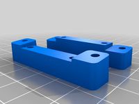
The Steering:
There are 2 different C-Hubs, the long one is only for HSP 108015 and HSP 188015
There are 4 different Steering Blocks, the same types than in all MyRCCar publications
There are 6 different Rear Fixed Blocks, 2 of them longer for HSP 108015 and HSP 188015
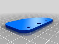
There are 4 different steering plates or "bars", one for each axle width. XL, L, M and S
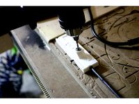
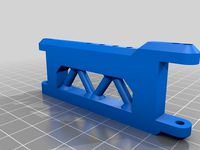
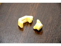
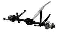
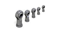
The links:
This links are Print in Place ball joint articulated. I use to print with -0.02 horizontal expansion to get the correct results, this time i printed them with -0.03 to be sure i could unlock them.
I have created some fixed length links and other parts to build variable length links.
This links have to adapt to the chosen wheelbase, from 145mm PWB to 165mm PWB. But also they have to adapt to the different axle types, the long, the medium and the short one. There are also 2 possibilities to assemble the bottom links in the long axle, you can mount them in the outer holders of the axle or the inner ones.
But resuming, using the variable length ones, wich are available in 2 lengths and for M3 or M4 screws, you will be able to have any of the needed measures.
Use the drawings to choose the right ones for your wheelbase and axle width from the fixed length ones or print 12 adjustable long heads for M3 or M4 as you preffer, and 4 adjustable short heads. Use M3x50 or M4x50 for the long ones and M3x40 or M4x40 for the short ones.
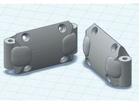
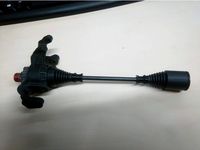
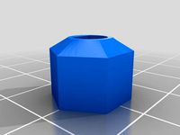
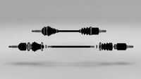
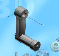
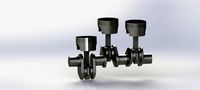
The Universal Shafts:
If you have the typical sourced parts for the MyRCCar projects, as 02024 with pinion and universal 1/10 vase for the F/R diffs, and a 1/8 center diff as the Trooper or the SST ones, then you can use this transmission.
There are 4 types of forks, they are:
Fork1, for 1/8 diff. This one goes into the 12mm output vase of the center diff and uses a M3x18mm Countersunk screw to act as torque transmitter and also to fix the fork to the vase
Fork2, connected with the Fork1 with the 11mm cube and 3mm piano wire portions, one 3x18mm piano wire part and two 3x7mm parts. I originally designed it to use M3x8 grub screws but they get out of place after some play, so better piano wire and loctite them. This fork also connects with the 12mm outer axle.
Fork3 is the one to mount on the 1/10 input vase of F/R diffs. Use a M4x5 grub screw to fix the Fork to the vase
Fork4 connects with Fork3 with same method than F1 with F2, and with the 10mm inner axle. Use M3x16 countersunk screws to fix the inner and outer axles to F2 and F4.
Take a look to the names of the different inner and outer axles of the universal shaft to have a clue about wich ones you need for your wheelbase and riding height!
The fake SST Fixed Differential:
Just two parts wich must be joined with 2 M3x8mm countersunk screws. Then use the normal adaptors and 12x18x4 bearings for your SST diff and mount the fake fixed diff. into the gearbox.
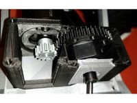
ATTENTION: The position of the motor is very important, and I have designed it to work with the gearbox and 14T pinion for the motor attaking a 28T gear. If this parameters changes then the motor can touch the universal shaft or the lower links, the space is very important in this build!
Other Things:
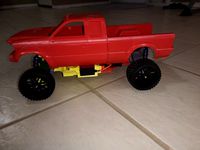
I created a Battery Box for the standard top cover. I mounted it in the back but can be mounted in the front part too.
You must use the front platform inverted in vertical and front/back in combination with links_FrontPlatformHolder. You don't need rear platform
You can put ESC and reciever over front platform if you mount the Battery Box in the back
Please analyze the info here and in the photos and drawings, the same than in previous MyRCCar projects and MyRCCar Group to solve great part of your doubts.
To examine and download the parts, please visit this publication
When I designed MTC Chassis I knew I wanted to be able to build an "hybrid", a rc car with independent suspension in the front and rigid axle in the back, but I have gone a little more far...
Now you can reuse some of the original MTC Chassis printed parts to build a Monster Truck / Crawler with rigid axles, 4 link suspension system and universal shafts, I think they call it like that to double cardan variable length transmissions.
Hey! No video by now :( Anyway suscribe or visit my Youtube Channel to see previous videos from the MTC Chassis and the Pickup
I'm a little tired right now to write up very specific instructions, maybe by now this publication is just for "experts" like those who can recieve instructions directly from the shapes of the design and logic patterns.
The Axles:
As you can see there are 3 different center parts for the axles. This will give you 3 different wides for your axles... You just have to choose. But there is also a wider one using the long axle and the "long C-Hubs" or "long rear fixed blocks".
You can use 4 different CVDs with the long axle plus 2 more with the long c-hubs
You can use 2 different CVD combinations with the medium axle
You can use 2 different CVDs with the small axle
The Steering:
There are 2 different C-Hubs, the long one is only for HSP 108015 and HSP 188015
There are 4 different Steering Blocks, the same types than in all MyRCCar publications
There are 6 different Rear Fixed Blocks, 2 of them longer for HSP 108015 and HSP 188015
There are 4 different steering plates or "bars", one for each axle width. XL, L, M and S
The links:
This links are Print in Place ball joint articulated. I use to print with -0.02 horizontal expansion to get the correct results, this time i printed them with -0.03 to be sure i could unlock them.
I have created some fixed length links and other parts to build variable length links.
This links have to adapt to the chosen wheelbase, from 145mm PWB to 165mm PWB. But also they have to adapt to the different axle types, the long, the medium and the short one. There are also 2 possibilities to assemble the bottom links in the long axle, you can mount them in the outer holders of the axle or the inner ones.
But resuming, using the variable length ones, wich are available in 2 lengths and for M3 or M4 screws, you will be able to have any of the needed measures.
Use the drawings to choose the right ones for your wheelbase and axle width from the fixed length ones or print 12 adjustable long heads for M3 or M4 as you preffer, and 4 adjustable short heads. Use M3x50 or M4x50 for the long ones and M3x40 or M4x40 for the short ones.
The Universal Shafts:
If you have the typical sourced parts for the MyRCCar projects, as 02024 with pinion and universal 1/10 vase for the F/R diffs, and a 1/8 center diff as the Trooper or the SST ones, then you can use this transmission.
There are 4 types of forks, they are:
Fork1, for 1/8 diff. This one goes into the 12mm output vase of the center diff and uses a M3x18mm Countersunk screw to act as torque transmitter and also to fix the fork to the vase
Fork2, connected with the Fork1 with the 11mm cube and 3mm piano wire portions, one 3x18mm piano wire part and two 3x7mm parts. I originally designed it to use M3x8 grub screws but they get out of place after some play, so better piano wire and loctite them. This fork also connects with the 12mm outer axle.
Fork3 is the one to mount on the 1/10 input vase of F/R diffs. Use a M4x5 grub screw to fix the Fork to the vase
Fork4 connects with Fork3 with same method than F1 with F2, and with the 10mm inner axle. Use M3x16 countersunk screws to fix the inner and outer axles to F2 and F4.
Take a look to the names of the different inner and outer axles of the universal shaft to have a clue about wich ones you need for your wheelbase and riding height!
The fake SST Fixed Differential:
Just two parts wich must be joined with 2 M3x8mm countersunk screws. Then use the normal adaptors and 12x18x4 bearings for your SST diff and mount the fake fixed diff. into the gearbox.
ATTENTION: The position of the motor is very important, and I have designed it to work with the gearbox and 14T pinion for the motor attaking a 28T gear. If this parameters changes then the motor can touch the universal shaft or the lower links, the space is very important in this build!
Other Things:
I created a Battery Box for the standard top cover. I mounted it in the back but can be mounted in the front part too.
You must use the front platform inverted in vertical and front/back in combination with links_FrontPlatformHolder. You don't need rear platform
You can put ESC and reciever over front platform if you mount the Battery Box in the back
Please analyze the info here and in the photos and drawings, the same than in previous MyRCCar projects and MyRCCar Group to solve great part of your doubts.
Similar models
thingiverse
free

MyRCCar 1/10 12mm Wheel HEX (for HSP 188015 CVD) by BotYoyo
...12mm wheel hex (for hsp 188015 cvd) by botyoyo
thingiverse
this is a wheel hex remix for myrccar if you are using hsp 188015 cvd
thingiverse
free
Adapter to fit NiKO2On's printed HSP 02024 gear into dlb5's MTC Diff by Saccco
...'s myrccar central differential housing for hsp02024 diff conversion, sst09304 and other 1/8 diffs. check remix links for it.
thingiverse
free

front axle with HSP 02024 diff flipped
... to make a dual front steerable axle truck if you pair it with this dual shaft version:
https://www.thingiverse.com/thing:3967894
thingiverse
free
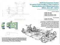
MyRCCar Suspension System for various CVDs including C-Hubs, 4 types of Steering Blocks and 3 different lower and upper arms (OLD) by dlb5
...hole car in the related myrccar group. please join us or make your questions there if they are not directly related to this thing
thingiverse
free

MyRCCar Center Diff. Remote Locking System by dlb5
... myrccar group and don't forget to introduce yourself! :)
note: the shared main body part is for a fixed blocked center diff.
thingiverse
free

MyRCCar MTC Parts (Updated) by Saccco
...central diff housing, now it's closed. it has a similar slide-in mechanism to be able to easily mount the...
sketchfab
$17

MyRCCar MTC Total Combo 1/10 RC Off-Road Chassis
...
have fun printing, building and driving! - myrccar mtc total combo 1/10 rc off-road chassis - buy royalty free 3d model by dlb5
thingiverse
free

MyRCCar MTC Chassis Building Instructions: Make your Monster Truck or Crawler RC car by dlb5
...the wheelbase. the main measures for the chassis are similar to the ones of an axial scx10 and allow...
thingiverse
free

MyRCCar OBTS Chassis Building Instructions by dlb5
...be build with 3 different sizes of bearings. something similar happens with the normal buggy / truggy cvds, there...
thingiverse
free

MyRCCar Central Differential Housing for HSP02024 Diff conversion, SST09304 and other 1/8 diffs. by dlb5
... it will fit in myrccar universal chassis. also please join the myrccar group to help improving myrccar, yourrccar i hope soon ;)
Dlb5
thingiverse
free
Adapter to fit NiKO2On's printed HSP 02024 gear into dlb5's MTC Diff by Saccco
...'s myrccar central differential housing for hsp02024 diff conversion, sst09304 and other 1/8 diffs. check remix links for it.
thingiverse
free

MyRCBike NSR500, First 1/5 3D Printed Hobby Level RC Bike: number 5 by dlb5
...st test ride of the v1 bike here:https://youtu.be/0ou5d9lsckc
if you want to find the full publication please come to see it here
thingiverse
free
MyRCCar MTC Styled Lower Suspension Arm 769 (even easier to print) by Saccco
...769 (even easier to print) by saccco thingiverse thanks dlb5 made my own version of the lower arms. intended...
thingiverse
free

MyRCCar 1/10 Buggy / Truggy LED Lights Holders (OLD) by dlb5
...ore space for shocks or due to caster.
i hope "you see the light" with this thing and start making your myrccar soon!!!
thingiverse
free
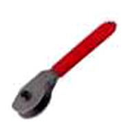
MyRCCar Dogbone Making Tool by dlb5
...t;martir" table, so, one time you have drill the backpart of the thing you don't drill the floor or something undesired.
thingiverse
free
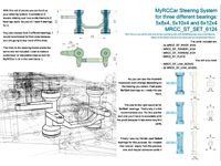
MyRCCar Steering System for three different bearings: 5x8x4, 5x10x4 and 6x12x4 by dlb5
... would be related more to the whole proyect please join the myrccar group. i hope i see you there soon building your own rc car:)
thingiverse
free
MyRCCar Center Diff. Remote Locking System by dlb5
... myrccar group and don't forget to introduce yourself! :)
note: the shared main body part is for a fixed blocked center diff.
thingiverse
free

Airbrush CNC Support and control with Marlin (OLD) by dlb5
...ease take a look at this video:video you can now also take a look to 5my first attemps airbrushing cmyk
will you give it a try?¿?
thingiverse
free
MyRCCar OBTS Chassis Building Instructions by dlb5
... shell, bumper, wing and lights
myrccar 1/10 buggy / truggy led lights holders. rc car light show!
myrccar 1/10 4th build testing
thingiverse
free
MyRCCar 1/10 Truggy rc car. With TITAN Shell, Bumper, Wing and Lights (OLD) by dlb5
...he car to put the shell lower or maybe accomodate some foam.
hope you like it and start soon making your own 3d printed rc car :)
Myrccar
thingiverse
free
Tarmo3 with myrccar truck body
...tarmo3 with myrccar truck body
thingiverse
i made a new front mount for the myrccar to connect to the tarm o3
thingiverse
free

Shock Spacer for MyRCCar by BotYoyo
...shock spacer for myrccar by botyoyo
thingiverse
you may need this shock spacer for some of the 1/10 shocks.
thingiverse
free
MyRCCar 1/10 12mm Wheel HEX (for HSP 188015 CVD) by BotYoyo
...12mm wheel hex (for hsp 188015 cvd) by botyoyo
thingiverse
this is a wheel hex remix for myrccar if you are using hsp 188015 cvd
thingiverse
free
MyRCCAR MTC Servo On Front RigAixs
...ing servo on the front bridge will keep the chasiss more stable when turning, so i give a try. and it works better as expected :)
thingiverse
free
MyRCCar LAS 0C and 6C for Ø3.0 x 56mm suspension rod by BotYoyo
...ension rod for myrccar. you may noticed the whole is not deep enough for the rod. this remix has deeper holes could fit 56mm rod.
thingiverse
free
MyRCCar MTC Improved Lower Suspension Arm 769 (easier to printer) by BotYoyo
...good. by not increase the weight, i just remix it to make it stronger and much easier to print. (maybe looks a little better? xd)
thingiverse
free
MyRCCar MTC Parts (Updated) by Saccco
...m.
for the complete chassis head on to dlb5's: myrccar 1/10 monster /crawler chassis with configurable 270 to 330mm wheelbase
thingiverse
free
MyRCCar OBTS Chassis Building Instructions by dlb5
... shell, bumper, wing and lights
myrccar 1/10 buggy / truggy led lights holders. rc car light show!
myrccar 1/10 4th build testing
thingiverse
free
Stronger Lower Arm Holder for MyRCCar MTC by BotYoyo
...ot which i broke it by a 0.3m height landing.
i just added some extra plastic to the weak spot. now the lower arm is rock solid!
thingiverse
free
MyRCCar MTC Styled Lower Suspension Arm 769 (even easier to print) by Saccco
...by saccco
thingiverse
thanks dlb5!
made my own version of the lower arms. intended to print without support.
hexa and m support.
Cvds
thingiverse
free
MyRCCar 1/10 12mm Wheel HEX (for HSP 188015 CVD) by BotYoyo
...12mm wheel hex (for hsp 188015 cvd) by botyoyo
thingiverse
this is a wheel hex remix for myrccar if you are using hsp 188015 cvd
thingiverse
free
X-Maxx CVD boot adapters
...hpi baja on x-maxx. then you can grease the cvds and stop wearing them like crazy. it also looks...
thingiverse
free

OpenRC Tuggy Wheel Hub for HSP CVD 108mm (HSP 188015) by hylpro
.../30 uploading v3
b.t.w this stl is generated by python program based on decscad library:http://www.thingiverse.com/thing:589749
thingiverse
free
MyRCCar Suspension System for various CVDs including C-Hubs, 4 types of Steering Blocks and 3 different lower and upper arms (OLD) by dlb5
...hole car in the related myrccar group. please join us or make your questions there if they are not directly related to this thing
thingiverse
free

Hex 17mm HSP 188015 by NiKO2On
...hex 17mm hsp 188015 by niko2on
thingiverse
хексы 17мм для cvd приводов hsp 188015
abs
0.25mm
thingiverse
free

Tamiya TT01 High angle steering ARM by cars1dA
...tamiya tt01 high angle steering arm by cars1da
thingiverse
created for tamiya tt01.
steering arm for cvd outshaft.
thingiverse
free
Hex 12mm HSP 188015 v1.0 by NiKO2On
...hex 12mm hsp 188015 v1.0 by niko2on
thingiverse
хексы для cvd приводов hsp 188015
abs
0.2mm
thingiverse
free

124019 144001 M4 wheel axel mod by bernitz
...quest for something stronger... i eventually came upon the cvds for the 12428 which have m4 hubs with a...
thingiverse
free
Front Assembly OpenRC Truggy for HSP 188015 (Remix) by NiKO2On
...vers by 2 mm so that the cvd drive does not drop out of the differential cup.
he made curved levers.
https://youtu.be/6yw1uc2nuwm
thingiverse
free
TLR Losi 8ight 3.0 Mudguard by CS-designs
...s a strainer for the rear cvd`s for losi 8ight 3.0.
screw for stabilizer bracket is stopped point screws for mounting with 2 m3 .
Mtc
cg_studio
$10

MTC3d model
...mtc3d model
cgstudio
.obj .mb .ma .dae - mtc 3d model, royalty free license available, instant download after purchase.
thingiverse
free

GADGET POST-IT by mtc
...gadget post-it by mtc
thingiverse
pla
sharebot ng
thingiverse
free
PORTA BOBINA by mtc
...porta bobina by mtc
thingiverse
porta bobina per stampante sharebot ng
thingiverse
free

ATTENTI AL CANE by mtc
...attenti al cane by mtc
thingiverse
sharebot ng
thingiverse
free

ORGANIZE NAIL POLISH by mtc
...organize nail polish by mtc
thingiverse
sharebot ng
thingiverse
free
MTC Swat scope focus ring by mattvokes1983
...mtc swat scope focus ring by mattvokes1983
thingiverse
scope focus ring for the 52x12 mtc swat scope
thingiverse
free

MTC Prismatic SWAT scope focus ring by WrightWells
...ocus ring by wrightwells
thingiverse
this fits snugly on to the mtc prismatic swat atom scope 10x30.
it may fit other mtc scopes
thingiverse
free
PACKAGE CIGARETTES by mtc
...d on the project http://www.thingiverse.com/thing:173316 , created for cigarettes compact and small bic .
contains 5-6 cigarettes
thingiverse
free

GADGET FOR POST-IT by mtc
...have printed with pla and low resolution and i think it's great, you could print a material flex to improve the closing book.
thingiverse
free
MyRCCAR MTC Servo On Front RigAixs
...ing servo on the front bridge will keep the chasiss more stable when turning, so i give a try. and it works better as expected :)
330Mm
turbosquid
$15

Steering Wheel Victor 330mm
... available on turbo squid, the world's leading provider of digital 3d models for visualization, films, television, and games.
3ddd
$1

96 Molecules Floor Lamp
...lamp размеры большой: w-350mm, d-350mm, h-1260mm размеры малой: w-330mm, d-330mm ...
3ddd
free

Vase Sigma VS100
...vase from sigma l2 collection 2013 d: 330mm h: 1330mm ...
3d_export
$12

lantern cd0801 house doctor
...in corona render<br>polygons: 17 184<br>vertices: 17 250<br>measure: x=330mm i y=330mm i...
3ddd
$1

Calligaris - Andromeda
...модели :cs/8016-sl описание: люстра страна / country: италия габариты :330mm h 1002mm сайт::http://www.calligaris.it/матерьялы все vray...
3ddd
free
Centra 90
...размеры раковина: w-895mm, d-625mm, h-200mm размеры смеситель: w-140mm, d-245mm, h-330mm ...
3ddd
$1
Plus plustcollection / Gumball
...размеры кресла: w-950mm, d-870mm, h-620mm размеры стола: w-780mm, d-780mm, h-330mm ...
3ddd
$1

YAMAGIWA: Wan T
...: white materials : glass / aluminium dimensions : d-330mm x h-205mm lamp type : halogen or led -...
3ddd
$2
Jonathan Sainsbury Chippendale Fret Bedside Table
...legs united by a pierced stretcher. height 670mm/26.4 width 330mm13 depth 330mm/13 the model is based on the original...
3ddd
$1

Декоративный набор для детской комнаты
...игрушечные счеты "мула" ikea ширина: 390mm, глубина: 180mm, высота: 330mm артикул 602.948.82 - коробка картонная для игрушек 160x160mm -...
Wheelbases
turbosquid
$24

BLENDER EEVEE Brandless Extended Wheelbase 4 door sedan
...ee brandless extended wheelbase 4 door sedan for download as on turbosquid: 3d models for games, architecture, videos. (1402654)
turbosquid
$11

BLENDER EEVEE Brandless Extended Wheelbase 2 door sedan
...ee brandless extended wheelbase 2 door sedan for download as on turbosquid: 3d models for games, architecture, videos. (1403448)
turbosquid
$10

BLENDER EEVEE Brandless Extended Wheelbase 2 door coupe
...ee brandless extended wheelbase 2 door coupe for download as on turbosquid: 3d models for games, architecture, videos. (1403164)
turbosquid
$10

BLENDER EEVEE Brandless Extended Wheelbase 4 door wagon
...ee brandless extended wheelbase 4 door wagon for download as on turbosquid: 3d models for games, architecture, videos. (1403156)
turbosquid
$10

BLENDER EEVEE Brandless Extended Wheelbase 4 door wagon
...ee brandless extended wheelbase 4 door wagon for download as on turbosquid: 3d models for games, architecture, videos. (1403154)
turbosquid
$10

BLENDER EEVEE Brandless Extended Wheelbase 2 door coupe
...ee brandless extended wheelbase 2 door coupe for download as on turbosquid: 3d models for games, architecture, videos. (1403151)
turbosquid
$9

BLENDER EEVEE Brandless Extended Wheelbase 4 door sedan
...ee brandless extended wheelbase 4 door sedan for download as on turbosquid: 3d models for games, architecture, videos. (1402829)
turbosquid
$8

BLENDER EEVEE Brandless Extended Wheelbase 4 door coupe
...ee brandless extended wheelbase 4 door coupe for download as on turbosquid: 3d models for games, architecture, videos. (1402352)
turbosquid
$8

BLENDER EEVEE Brandless Extended Wheelbase 4 door sedan
...ee brandless extended wheelbase 4 door sedan for download as on turbosquid: 3d models for games, architecture, videos. (1402342)
turbosquid
$7

BLENDER EEVEE Brandless Extended Wheelbase 2 door sedan
...ee brandless extended wheelbase 2 door sedan for download as on turbosquid: 3d models for games, architecture, videos. (1402337)
290
design_connected
$27

DC 290
...dc 290
designconnected
ceccotti collezioni dc 290 computer generated 3d model. designed by de cotiis, vincenzo.
turbosquid
$15

LA A 290
... available on turbo squid, the world's leading provider of digital 3d models for visualization, films, television, and games.
turbosquid
$15

LG A 290
... available on turbo squid, the world's leading provider of digital 3d models for visualization, films, television, and games.
design_connected
$16
290 Cantilever Chair
...290 cantilever chair
designconnected
cado 290 cantilever chair computer generated 3d model. designed by østergaard, steen.
3ddd
free
Gaggenau CG 290
...b , варочная панель
gaggenau cg 290 model.
cooking hob, with unwrapped texture for logo.
3d_export
$15

LG A 290 3D Model
...lg a 290 3d model
3dexport
lg
lg a 290 3d model haiviet3d 58889 3dexport
turbosquid
$25

DC-290-Sofa
... available on turbo squid, the world's leading provider of digital 3d models for visualization, films, television, and games.
turbosquid
$2
Decorative panel 290
...orative panel 290 for download as max, max, fbx, obj, and stl on turbosquid: 3d models for games, architecture, videos. (1624636)
3ddd
$1

Ceccotti DC 290
...ceccotti dc 290
3ddd
ceccotti
3d max 2009,vray 1.5 sp2+fbx
turbosquid
$20

Sofa Ceccotti DC 290
... available on turbo squid, the world's leading provider of digital 3d models for visualization, films, television, and games.
Rigid
turbosquid
$15
Rigid Bag Filter
... available on turbo squid, the world's leading provider of digital 3d models for visualization, films, television, and games.
turbosquid
free

Rigid body Cube
... available on turbo squid, the world's leading provider of digital 3d models for visualization, films, television, and games.
3d_export
$12

Semi Rigid Rubberduck 3D Model
... tender yacht marine boat rigid bottom inflatable dinghy run-around 38m
semi rigid rubberduck 3d model southdesign 32727 3dexport
turbosquid
$35

Among Us Rigid Character
...among us rigid character for download as blend, obj, and fbx on turbosquid: 3d models for games, architecture, videos. (1637362)
3d_export
$15
Rigid Bag Filter 3D Model
...rigid bag filter 3d model
3dexport
filter bag clean air ahu conditioning
rigid bag filter 3d model matvic 85845 3dexport
3d_export
$60

Rabbit Rigid 3D Model
...oe hare burrow long ears pet 3d realistic rigged white brown fur small cute mammal
rabbit rigid 3d model scorpio47 78247 3dexport
cg_studio
$119

Mercedes Antos rigid truck3d model
... .fbx .lwo .max .obj .xsi - mercedes antos rigid truck 3d model, royalty free license available, instant download after purchase.
3d_export
$119

Mercedes Antos rigid truck 3D Model
...os actros van boxtruck trailer heavy daimler german european rigid
mercedes antos rigid truck 3d model fisherman3d 66670 3dexport
3d_export
$50

of a hydrofoil board with a rigid wing sail
...model is made in the form of: hull parts, sail parts, as well as a ballast centerboard and keel.<br>all peace and goodness.
turbosquid
$12
Device for loading and unloading of non-rigid CME roller tracks
... available on turbo squid, the world's leading provider of digital 3d models for visualization, films, television, and games.
Axle
3d_export
$5
axle knob
...axle knob
3dexport
axle knob
turbosquid
$3

Axle-loadLimitroadsign
...loadlimitroadsign for download as 3ds, dae, fbx, obj, and stl on turbosquid: 3d models for games, architecture, videos. (1532898)
3d_export
$30
Car axle 3D Model
...e transmission drive power assembly gear rear wheel step maya softimage fbx vray
car axle 3d model sunshineweilian 99506 3dexport
3d_ocean
$12

Exploded Half Axle
.... the model is built out of quads and is subdivisable. different parts are separate for ease of handle. the model comes in 5 f...
turbosquid
$50

Trommel_1 Line Axle
... available on turbo squid, the world's leading provider of digital 3d models for visualization, films, television, and games.
turbosquid
$39
DUALLY AXLE AND DRIVESHAFT
... and driveshaft for download as max, blend, fbx, obj, and 3ds on turbosquid: 3d models for games, architecture, videos. (1653704)
3d_ocean
$9

Half Axle
...el is built out of quads and is subdivisable. different parts are separate for ease of handle. the model comes in 4 formats: -...
3d_export
$50
Exploded Half Axle 3D Model
...shaft drive gearbox wheel velocity constant engine chassis part planetary
exploded half axle 3d model dragosburian 93254 3dexport
turbosquid
$50

Trommel 2 Line Axles
... available on turbo squid, the world's leading provider of digital 3d models for visualization, films, television, and games.
turbosquid
$39
rear axle dual rim
... available on turbo squid, the world's leading provider of digital 3d models for visualization, films, television, and games.
Axles
3d_export
$5
axle knob
...axle knob
3dexport
axle knob
turbosquid
$3
Axle-loadLimitroadsign
...loadlimitroadsign for download as 3ds, dae, fbx, obj, and stl on turbosquid: 3d models for games, architecture, videos. (1532898)
3d_export
$30
Car axle 3D Model
...e transmission drive power assembly gear rear wheel step maya softimage fbx vray
car axle 3d model sunshineweilian 99506 3dexport
3d_ocean
$12
Exploded Half Axle
.... the model is built out of quads and is subdivisable. different parts are separate for ease of handle. the model comes in 5 f...
turbosquid
$50
Trommel_1 Line Axle
... available on turbo squid, the world's leading provider of digital 3d models for visualization, films, television, and games.
turbosquid
$39
DUALLY AXLE AND DRIVESHAFT
... and driveshaft for download as max, blend, fbx, obj, and 3ds on turbosquid: 3d models for games, architecture, videos. (1653704)
3d_ocean
$9
Half Axle
...el is built out of quads and is subdivisable. different parts are separate for ease of handle. the model comes in 4 formats: -...
3d_export
$50
Exploded Half Axle 3D Model
...shaft drive gearbox wheel velocity constant engine chassis part planetary
exploded half axle 3d model dragosburian 93254 3dexport
turbosquid
$50
Trommel 2 Line Axles
... available on turbo squid, the world's leading provider of digital 3d models for visualization, films, television, and games.
turbosquid
$39
rear axle dual rim
... available on turbo squid, the world's leading provider of digital 3d models for visualization, films, television, and games.
Shafts
3d_export
$5
shaft handle
...shaft handle
3dexport
shaft handle
3d_export
$5

shaft bracket
...shaft bracket
3dexport
shaft bracket
turbosquid
$3

Shaft
... available on turbo squid, the world's leading provider of digital 3d models for visualization, films, television, and games.
turbosquid
$2

shaft
... available on turbo squid, the world's leading provider of digital 3d models for visualization, films, television, and games.
3d_export
free
crank shaft
...crank shaft
3dexport
crank shaft with piston with different materials
3d_export
$8
shaft bearing
...shaft bearing
3dexport
shaft bearing m10, m12,m16, m20 and m27
3d_export
$5
hexagonal shaft knob
...hexagonal shaft knob
3dexport
hexagonal shaft knob
3d_export
$5
shaft hand wheel
...shaft hand wheel
3dexport
shaft hand wheel
3d_export
$5
triangular shaft knob
...triangular shaft knob
3dexport
triangular shaft knob
3d_export
$5
octagonal shaft knob
...octagonal shaft knob
3dexport
octagonal shaft knob
Universal
3d_export
$20
university
...university
3dexport
university model with textures.
3d_export
free

steven universe
...steven universe
3dexport
steven universe
3ddd
free

Quasar Universe
...quasar universe
3ddd
quasar
люстра quasar universe
turbosquid
$65
Universal
... available on turbo squid, the world's leading provider of digital 3d models for visualization, films, television, and games.
turbosquid
$65

University
... available on turbo squid, the world's leading provider of digital 3d models for visualization, films, television, and games.
turbosquid
$5

Universal
... available on turbo squid, the world's leading provider of digital 3d models for visualization, films, television, and games.
3d_export
$40
Graphics Universe Universe Flares 3D Model
...graphics universe universe flares 3d model
3dexport
textures
graphics universe universe flares 3d model crashangel 97554 3dexport
3d_export
$65

universe
...universe
3dexport
simple rendering of the scene file
3d_export
$65

university
...university
3dexport
simple rendering of the scene file
3ddd
$1
Gala Universal раковина
...universal раковина
3ddd
gala , universal
раковина
производитель gala
коллекция universal
Wides
turbosquid
$19

Wide curtains
...bosquid
royalty free 3d model wide curtains for download as on turbosquid: 3d models for games, architecture, videos. (1610514)
3ddd
$1
Стул COSMO Wide
...mo , wide
производитель cosmo
модель wide
высота (см)78,5
ширина (см)50
глубина (см)50,5
turbosquid
$39

Wide Shelf
... available on turbo squid, the world's leading provider of digital 3d models for visualization, films, television, and games.
turbosquid
$29

Wide sword
... available on turbo squid, the world's leading provider of digital 3d models for visualization, films, television, and games.
3ddd
$1

Стол кофейный Wide Loop
...стол кофейный wide loop
3ddd
кофейный
стол кофейный wide loop
turbosquid
$19

Wide beige curtains
...royalty free 3d model wide beige curtains for download as max on turbosquid: 3d models for games, architecture, videos. (1443776)
turbosquid
$19

Wide brown curtains
...royalty free 3d model wide brown curtains for download as max on turbosquid: 3d models for games, architecture, videos. (1443144)
turbosquid
$19

Wide brown curtains
...royalty free 3d model wide brown curtains for download as max on turbosquid: 3d models for games, architecture, videos. (1459908)
turbosquid
$10

Capitol Wide Lantern
...oyalty free 3d model capitol wide lantern for download as max on turbosquid: 3d models for games, architecture, videos. (1212606)
turbosquid
$5

Wide Gift Box
...id
royalty free 3d model wide gift box for download as blend on turbosquid: 3d models for games, architecture, videos. (1230868)
Different
turbosquid
free
Different Chair
...id
free 3d model different chair for download as max and fbx on turbosquid: 3d models for games, architecture, videos. (1642013)
turbosquid
free

different rubbish
... available on turbo squid, the world's leading provider of digital 3d models for visualization, films, television, and games.
3d_export
$10

Different 3D Model
...different 3d model
3dexport
different 3d model wintik174 96497 3dexport
3d_export
free
three different type
...three different type
3dexport
three different type: mace, axe, sword
3d_ocean
$10

Different types of gears
... industrial parts machine gears machine parts mechanics parts round shape
different types of machine parts/gears made in blender.
turbosquid
free

Wires in different colours
...ires in different colours for download as blend, fbx, and obj on turbosquid: 3d models for games, architecture, videos. (1652797)
turbosquid
$6
3 Different Arrows
...3d model 3 different arrows for download as 3ds, obj, and fbx on turbosquid: 3d models for games, architecture, videos. (1478401)
turbosquid
$4

Four Different Vases
...odel four different vases for download as obj, fbx, and blend on turbosquid: 3d models for games, architecture, videos. (1484813)
3d_ocean
$3

8 Different Stone
...ures : low poly mesh & hand painting texture ~contain normal map ~different mesh have any problem? feel free to contact me...
turbosquid
$45

Different Food Products
... food products for download as blend, max, fbx, gltf, and obj on turbosquid: 3d models for games, architecture, videos. (1614198)
10
turbosquid
$25

10
... available on turbo squid, the world's leading provider of digital 3d models for visualization, films, television, and games.
turbosquid
$10
a-10
... available on turbo squid, the world's leading provider of digital 3d models for visualization, films, television, and games.
3ddd
$1

EX 10
...ex 10
3ddd
samsung , фотоаппарат
ex 10
3ddd
$1
Bed 10
...bed 10
3ddd
постельное белье
bed 10
evermotion
$25
Scene 10 Archinteriors vol. 10
...dering design interior
take a look at textured and shadered visualization scene ready to be rendered.. evermotion 3d models shop.
3ddd
$1

Curtains 10
...curtains 10
3ddd
curtains 10
3ds max 2011,fbx + textures
polys: 100355
3ddd
free

PLANTS 10
...plants 10
3ddd
цветок , горшок
plants 10,, with 3 different color planter boxes
turbosquid
$24

Chandelier MD 89310-10+10 Osgona
... chandelier md 89310-10+10 osgona for download as max and fbx on turbosquid: 3d models for games, architecture, videos. (1218762)
design_connected
$29
Nuvola 10
...nuvola 10
designconnected
gervasoni nuvola 10 computer generated 3d model. designed by navone, paola.
design_connected
$22

Kilt 10
...kilt 10
designconnected
zanotta kilt 10 computer generated 3d model. designed by progetti, emaf.
8
turbosquid
$6

Rock 8-8
...urbosquid
royalty free 3d model rock 8-8 for download as obj on turbosquid: 3d models for games, architecture, videos. (1659393)
3ddd
$1
Italamp 387/8+8
...italamp 387/8+8
3ddd
italamp
люстра italamp 387/8+8
размеры 92x71h
3ddd
$1

8 марта
...8 марта
3ddd
8 марта
кресло 8 марта
design_connected
$16

No 8
...nected
photo-realistic 3d models of the sibast no 8 armchair from sibast for 3d architectural and interior design presentations.
3d_export
$5
hinge 8
...hinge 8
3dexport
hinge 8
3d_export
$5

iphone 8
...iphone 8
3dexport
iphone 8
turbosquid
$69

iPhone 8 and iPhone 8 Plus
... free 3d model iphone 8 and iphone 8 plus for download as max on turbosquid: 3d models for games, architecture, videos. (1202442)
turbosquid
$12

Calligraphic Digit 8 Number 8
...hic digit 8 number 8 for download as max, obj, fbx, and blend on turbosquid: 3d models for games, architecture, videos. (1389341)
3ddd
free

PLANTS 8
...plants 8
3ddd
цветок , горшок
plant 8,,, hope u all like it
3ddd
$1
8 Марта / Amadey
...8 марта / amadey
3ddd
8 марта
8 marta amadey
4
turbosquid
$9

Office Chair 4-4
... available on turbo squid, the world's leading provider of digital 3d models for visualization, films, television, and games.
3d_export
$5

doors- 4
...doors- 4
3dexport
doors 4
3d_export
$5
hinge 4
...hinge 4
3dexport
hinge 4
3ddd
$1

Штора №4
...штора №4
3ddd
штора №4
3d_export
free

playstation 4
...playstation 4
3dexport
playstation 4
turbosquid
$1
re 4-4 electric locomotive
... free 3d model re 4 4 electric locomotive for download as obj on turbosquid: 3d models for games, architecture, videos. (1707845)
3ddd
$1

nexus 4
...nexus 4
3ddd
lg , телефон
nexus 4
3ddd
$1
4 Poufs
...4 poufs
3ddd
пуф
4 soft poufs
turbosquid
$12

Calligraphic Digit 4 Number 4
...hic digit 4 number 4 for download as max, obj, fbx, and blend on turbosquid: 3d models for games, architecture, videos. (1389332)
3ddd
$1
Dauphin 4+
...dauphin 4+
3ddd
кресло
dauphin 4+ конференц кресло
1
turbosquid
$69
armchairs(1)(1)
... available on turbo squid, the world's leading provider of digital 3d models for visualization, films, television, and games.
turbosquid
$15
ring 1+1
... available on turbo squid, the world's leading provider of digital 3d models for visualization, films, television, and games.
turbosquid
$10
chair(1)(1)
... available on turbo squid, the world's leading provider of digital 3d models for visualization, films, television, and games.
turbosquid
$8

Chair(1)(1)
... available on turbo squid, the world's leading provider of digital 3d models for visualization, films, television, and games.
turbosquid
$2

RING 1(1)
... available on turbo squid, the world's leading provider of digital 3d models for visualization, films, television, and games.
turbosquid
$1
house 1(1)
... available on turbo squid, the world's leading provider of digital 3d models for visualization, films, television, and games.
turbosquid
$1

Table 1(1)
... available on turbo squid, the world's leading provider of digital 3d models for visualization, films, television, and games.
turbosquid
$59

Formula 1(1)
...lty free 3d model formula 1 for download as max, fbx, and obj on turbosquid: 3d models for games, architecture, videos. (1567088)
design_connected
$11
No 1
...no 1
designconnected
sibast no 1 computer generated 3d model. designed by sibast, helge.
turbosquid
$2
desert house(1)(1)
...3d model desert house(1)(1) for download as 3ds, max, and obj on turbosquid: 3d models for games, architecture, videos. (1055095)