Thingiverse

Multi Function Display For Elite Dangerous by EldragonFromSA
by Thingiverse
Last crawled date: 3 years, 4 months ago
What is it?
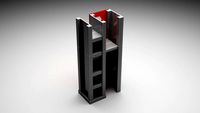
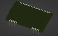
This is a functional button box with built in screen for use in Elite Dangerous or any other flight simulator that can output game data to a second monitor.
The back of the box has mounting holes for a 75mm x 75mm VESA mount. You can find many stands to pick from on Thingiverse. I used this one.
What is Inside?
A 7 inch HDMI screen, and adruino keyboard emulator tied to 12 Cherry MX Buttons. In the case of Elite Dangerous, it uses Status Display to provide game data to the screen, and simple key bindings set in game.
What you need to build this?
7.1 inch Touchscreen for Rasberry Pi. I used an Osoyoo model. In theory any brand should work. I left the cutout on the right side open to support as many models as possible. However don't trust my mounting holes to fit your screen. Double check them yourself.
1x Adruino Pro Micro
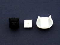
12x Cherry MX Switches
12x Cherry MX Keycaps. (You can print up your own of course. Not included here)
4x M3x16 mm Socket Head bolts.
A piece of double sided 3M wall tape. (the thick kind you use to hang pictures)
Wire, solder, and the knowledge of how to use it. I STRONGLY suggest getting 7 colors of wire. Why 7? Because we are doing a 3x4 matrix. 3 rows, 4 columns.
How to make it
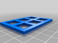
Print the two pieces posted here. If you can't figure out this step. Just give up now.
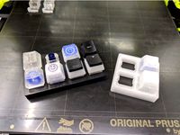
Place each of the Cherry MX switches into the square holes in the top plate.
Wire the Cherry MX Switches to the Adruino in a 3x4 matrix pattern. Take note of the pin numbers you used. You will need this later. Be sure to leave room for placing the monitor into the top plate.
Place screen face down into the top plate. I suggest partially screwing the M3 bolts into the top plate and screen.
Put the double sided tape on the back of the Arduino and place it in the cutout slot. (I really hope you tested your connections before you got this far)
Then flip the monitor+cover over and lower it into the base. Make sure you are not pinching wires.
Screw the m3 bolts into the base.
Use the Arduino code pasted below and load it into the Arduino IDE. You will need to download and install the Keypad library.
Check the keybindings and pins used in the code below, you may prefer alternative key bindings.
#include#include #include
#define NUMROWS 3#define NUMCOLS 4
//define the symbols on the buttons of the keypadschar buttons[NUMROWS][NUMCOLS] = {{'y', 'u', 'o', 'p'},{'h', 'j', 'k', 'l'},{'b', 'n', 'm', ','},};
byte rowPins[NUMROWS] = {16,5,4}; //connect to the row pinouts of the keypadbyte colPins[NUMCOLS] = {6,7,8,9}; //connect to the column pinouts of the keypad
Keypad keypad = Keypad( makeKeymap(buttons), rowPins, colPins, NUMROWS, NUMCOLS );
void setup(){Serial.begin(9600);Keyboard.begin();}
void loop(){char key = keypad.getKey();
if (key != NO_KEY){Keyboard.write( key );}}
This is a functional button box with built in screen for use in Elite Dangerous or any other flight simulator that can output game data to a second monitor.
The back of the box has mounting holes for a 75mm x 75mm VESA mount. You can find many stands to pick from on Thingiverse. I used this one.
What is Inside?
A 7 inch HDMI screen, and adruino keyboard emulator tied to 12 Cherry MX Buttons. In the case of Elite Dangerous, it uses Status Display to provide game data to the screen, and simple key bindings set in game.
What you need to build this?
7.1 inch Touchscreen for Rasberry Pi. I used an Osoyoo model. In theory any brand should work. I left the cutout on the right side open to support as many models as possible. However don't trust my mounting holes to fit your screen. Double check them yourself.
1x Adruino Pro Micro
12x Cherry MX Switches
12x Cherry MX Keycaps. (You can print up your own of course. Not included here)
4x M3x16 mm Socket Head bolts.
A piece of double sided 3M wall tape. (the thick kind you use to hang pictures)
Wire, solder, and the knowledge of how to use it. I STRONGLY suggest getting 7 colors of wire. Why 7? Because we are doing a 3x4 matrix. 3 rows, 4 columns.
How to make it
Print the two pieces posted here. If you can't figure out this step. Just give up now.
Place each of the Cherry MX switches into the square holes in the top plate.
Wire the Cherry MX Switches to the Adruino in a 3x4 matrix pattern. Take note of the pin numbers you used. You will need this later. Be sure to leave room for placing the monitor into the top plate.
Place screen face down into the top plate. I suggest partially screwing the M3 bolts into the top plate and screen.
Put the double sided tape on the back of the Arduino and place it in the cutout slot. (I really hope you tested your connections before you got this far)
Then flip the monitor+cover over and lower it into the base. Make sure you are not pinching wires.
Screw the m3 bolts into the base.
Use the Arduino code pasted below and load it into the Arduino IDE. You will need to download and install the Keypad library.
Check the keybindings and pins used in the code below, you may prefer alternative key bindings.
#include
#define NUMROWS 3#define NUMCOLS 4
//define the symbols on the buttons of the keypadschar buttons[NUMROWS][NUMCOLS] = {{'y', 'u', 'o', 'p'},{'h', 'j', 'k', 'l'},{'b', 'n', 'm', ','},};
byte rowPins[NUMROWS] = {16,5,4}; //connect to the row pinouts of the keypadbyte colPins[NUMCOLS] = {6,7,8,9}; //connect to the column pinouts of the keypad
Keypad keypad = Keypad( makeKeymap(buttons), rowPins, colPins, NUMROWS, NUMCOLS );
void setup(){Serial.begin(9600);Keyboard.begin();}
void loop(){char key = keypad.getKey();
if (key != NO_KEY){Keyboard.write( key );}}
Similar models
thingiverse
free
Cherry MX Macro Keypad by Relyk
...cherry mx switches to create a macro pad. the controller is an arduino pro micro. feel free to ask questions and i'll answer.
thingiverse
free

Arduino Pro Micro Cherry MX USB Numpad by PhobosTK
...ditional top row of keys that i've set to [play - voldown - volup - mute].
ps: i've used 1n4148 diodes for key debouncing
grabcad
free

Keypad Matrix 3X4 12 Key Numeric Waterproof
...keypad matrix 3x4 12 key numeric waterproof
grabcad
arduino 3x4 matrix keypad
thingiverse
free

Cherry Mx key by Oreshield
...erry mx key by oreshield
thingiverse
a key that you can use on a keyboard with cherry mx switches and other mechanical switches.
thingiverse
free

4 6 and 8 button Macro pads by Jebidiah_Crumps
...ne wire per switch to a pin on the arduino.
to code it use the arduino ide and this guide https://www.sparkfun.com/tutorials/337
thingiverse
free
Cherry MX Series keyswitch connector by okmh
...ies keyswitches".http://cherrycorp.com/english/switches/key/mx.htm
i have tested the data using up!plus and dimension elite.
thingiverse
free

20 percent key plate by _spindle
...ey plate by _spindle
thingiverse
a 4x6 key plate for cherry mx switches. i'm still working on refining the pcb and firmware.
grabcad
free

LED backlighted 3x4 stainless steel keypad
...mount metal illuminated key button usb backlit keypad,led backlighted 12 keys 3x4 stainless steel 10pin connector from aliexpress
thingiverse
free

Macro Keypad (8 mechanical keys + 1 dial) by ftxujie
...eet (optional)
wires
software
arduino ide
you can find the code and wiring from https://www.ftxujie.com/2020/11/macro-keypad.html
thingiverse
free
Parametric (Customizable) Cherry MX Key Switch Tester
... the corner (makes a great keychain/fidget toy). all examples have been re-rendered and the 1x1 model includes the keyring hole.
Elite
turbosquid
$1

Elit
... available on turbo squid, the world's leading provider of digital 3d models for visualization, films, television, and games.
3ddd
$1
Подвесы Elite Wire
... wire , подвес
подвесы фирмы elite коллекция wire
3ddd
free
Кухня Cesar Elite
... классическая , cesar elite
классическая кухня cesar elite
3ddd
$1
Настольная лампа Elite Wire
... wire
3ddd
elite wire , elite , wire
elite wire
turbosquid
$19

Steyr Elite
...osquid
royalty free 3d model steyr elite for download as fbx on turbosquid: 3d models for games, architecture, videos. (1537913)
turbosquid
$15

Elite Sofa
...bosquid
royalty free 3d model elite sofa for download as max on turbosquid: 3d models for games, architecture, videos. (1363420)
turbosquid
$9

Elite ring
...bosquid
royalty free 3d model elite ring for download as stl on turbosquid: 3d models for games, architecture, videos. (1228855)
3ddd
$1
Полотенцесушитель HAMMAM Elite
...hammam elite
размеры: 1440х500 (матовый)
производиетель: турцияhttp://www.odenemdom.ru/turtsiya-hammam-elite-44547.html
3ddd
$1
Столы серии Selecta elite
...lite , офисный , стол
столы серии selecta elite
turbosquid
$50
stolichnaya elit
... available on turbo squid, the world's leading provider of digital 3d models for visualization, films, television, and games.
Dangerous
turbosquid
$150

dangerous
... available on turbo squid, the world's leading provider of digital 3d models for visualization, films, television, and games.
turbosquid
$50

Danger
... available on turbo squid, the world's leading provider of digital 3d models for visualization, films, television, and games.
turbosquid
$2

Danger Singlet
...ree 3d model danger singlet for download as c4d, obj, and fbx on turbosquid: 3d models for games, architecture, videos. (1691344)
3d_export
free

Dangerous Material
...dangerous material
3dexport
render is a bit bad(
turbosquid
$39

Danger Sign
... available on turbo squid, the world's leading provider of digital 3d models for visualization, films, television, and games.
3d_export
$40
sakura danger moond
...sakura danger moond
3dexport
3d_export
$20
the ship is a dangerous merchant
...the ship is a dangerous merchant
3dexport
3d_export
$10
Danger Clown Female
...danger clown female
3dexport
3d_export
$10
Danger Mime Female
...danger mime female
3dexport
3d_export
$5
danger cat
...the mouth and the eyes, imagine a cat with shiny eyes, its seems scary.<br>but don't worry its getting cool in the day.
Function
turbosquid
$1

functional clock
...d
royalty free 3d model functional clock for download as fbx on turbosquid: 3d models for games, architecture, videos. (1378928)
turbosquid
$5

functional door
... model functional door for download as 3ds, obj, c4d, and stl on turbosquid: 3d models for games, architecture, videos. (1483785)
3d_export
$5
multi function box
...multi function box
3dexport
it is multi function box in iges format
3ddd
$1

Fitness Equipament - Functional
...fitness equipament - functional
3ddd
треножер
fitness equipament functional, modeled from real model.
turbosquid
$19

Four function formula
...
royalty free 3d model four function formula for download as on turbosquid: 3d models for games, architecture, videos. (1154985)
turbosquid
$1
functional work table
...yalty free 3d model functional work table for download as max on turbosquid: 3d models for games, architecture, videos. (1198733)
3d_export
free
Multi-functional anaquel
...multi-functional anaquel
3dexport
https://www.dock4all.com/
turbosquid
$12

Multi-Function Knife
... available on turbo squid, the world's leading provider of digital 3d models for visualization, films, television, and games.
turbosquid
$9

function x black coin
...yalty free 3d model function x black coin for download as max on turbosquid: 3d models for games, architecture, videos. (1457828)
turbosquid
$8

Multi-function cylinder mechanism
...lti-function cylinder mechanism for download as ige and sldpr on turbosquid: 3d models for games, architecture, videos. (1223739)
Multi
3d_export
$5
multi handle
...multi handle
3dexport
multi handle
3d_export
free
Multi socket
...multi socket
3dexport
multi socket
design_connected
$22

Multy Loveseat
...multy loveseat
designconnected
ligne roset multy loveseat 2-seater computer generated 3d model. designed by claude brisson.
turbosquid
$10
multi pan
...
royalty free 3d model multi pan for download as max and ige on turbosquid: 3d models for games, architecture, videos. (1161690)
turbosquid
$9

Multi Plug
...
royalty free 3d model multi plug for download as max and fbx on turbosquid: 3d models for games, architecture, videos. (1355953)
turbosquid
$39
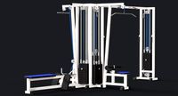
Multi Gym
...y free 3d model multi gym for download as obj, fbx, and blend on turbosquid: 3d models for games, architecture, videos. (1275571)
3ddd
free
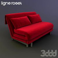
Ligne Roset Multy
... sofa , мебель
двухместный диван multy от французского производителя ligne roset
3d_export
$5

multi-colored pencils
...multi-colored pencils
3dexport
multi-colored pencils on a mirror surface
3d_export
$5
multi function box
...multi function box
3dexport
it is multi function box in iges format
3ddd
free
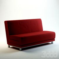
ligne roset / MULTY
...ligne roset / multy
3ddd
ligne roset , multy
минималистический диван
Display
3ddd
$1

Display
...display
3ddd
терминал
display computer 3d model
3d_export
$5
Display
...display
3dexport
display<br>verts 2.262<br>faces 3.928
turbosquid
$8

Display
...turbosquid
royalty free 3d model display for download as fbx on turbosquid: 3d models for games, architecture, videos. (1634534)
3ddd
$1
Display cabinet
...display cabinet
3ddd
витрина
display cabinet
turbosquid
$50

display
... available on turbo squid, the world's leading provider of digital 3d models for visualization, films, television, and games.
turbosquid
$25

DISPLAY
... available on turbo squid, the world's leading provider of digital 3d models for visualization, films, television, and games.
turbosquid
$10
Display
...e 3d model display for download as ma, max, obj, fbx, and dae on turbosquid: 3d models for games, architecture, videos. (1387472)
3d_export
$6
display stand
...display stand
3dexport
super market display stand
3d_ocean
$12
Display Case
...rnishing furniture glass storage vetrinetta white
a 3d model of a display case. the texture for the back of the case is provided.
3d_export
$30

Vehicle display
...vehicle display
3dexport
vehicle display consists of podium and vehicle cover no vehicle there is a veiled vehicle silhouette