Thingiverse
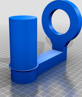
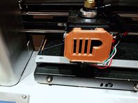
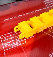
Monoprice Select Mini V2 bed cable re-route through 40mm fan hole by novaguy
by Thingiverse
Last crawled date: 3 years ago
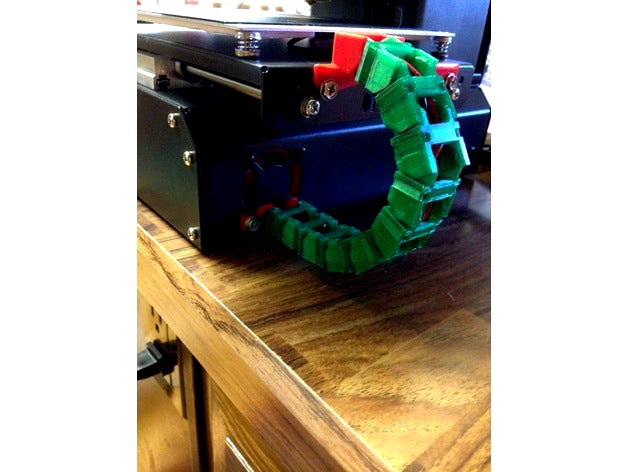
I had the common bed temp sensor issue with these printers. I repaired the wire and then sought to prevent the issue from happening again. I did not find exactly what I was looking for and decided to make my own. This is a re-mix of https://www.thingiverse.com/thing:2198351 inspired by https://www.thingiverse.com/thing:2376061
There is absolutely no cutting or drilling required for this mod. This works with a few different cable chain models out there. I used https://www.thingiverse.com/thing:611593/ for the ends, but I am actually using a cable chain that a friend had printed for me while my printer was down that I do not know the origin of. I needed 10 links for my application. It would be a good idea to print a few more than 10 just to be on the safe side.
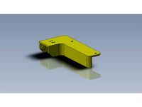
You will probably want to print the fan shroud with supports. If your printer does really long bridging well you may be able to get away with printing it upright without supports, but I did not try.
You will need to provide your own screws to mount the fan to the shroud and the fan opening chain adapter. 2 of the stock stock 40mm fan mounting screws can be used to mount the shroud to the back of the printer. You will also need to locate some screws (fairly short) and nuts to secure the bed mount part. I happened to have everything I needed in loose parts bins that I had around the hose so I do not know specifically what screws to recommend. You should print the parts and locate screws that will work before you try to stall the parts into the printer.
Installation instructions:
Note: Please only install this if you are comfortable working on mechanical and electronic devices. It should go without saying, but you are proceeding at your own risk. Be sure the printer is unplugged and cool before you begin.
Whenever handling wires be sure to not pull too hard on connectors. Also always be sure that all wires are clear when tightening any screw to avoid pinching the wire.
Do not over-tighten screws!
Tools required:
Phillips screw driver.
Something to cut wire ties.
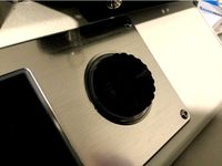
Remove the 4 screws that hold the 40mm fan in place on the back of the printer. You could probably do this later, but I found it easier to do this first.
Set printer on it's back and remove the 6 screws that hold the bottom to the chassis. Take care to support the bottom plate when removing the last screw so that it does not free-fall. You can also rotate the bottom panel 90 degrees (with the circuit board toward the back of the printer) to avoid disconnecting anything.
Locate and disconnect the bed heater and bed thermister wires from the circuit board.
Clip any wire ties holding these two wires in place.
Carefully route the two loose wires through the hole in the top of the chassis. You may need to push the rubber grommet through the hole in order to get the bed heater wire connector through the hole.
Put the bottom plate back in place loosely with just a couple screws and the turn the printer upright again.
Pull the two loose cables through the hole in the top of the chassis until they are clear of falling back inside. Note If you had to displace the rubber grommet to get the wires out of the chassis, you can put it back in place now.
Remove the print bed surface. TIP: If you use a caliper to measure the height of all 4 corners it makes re-leveling the bed a little easier when the printer is reassembled.
Cut the wire tie holding the wires to the underside of the print bed,
Pop the rubber grommet out of the print bed and pull the two loose wires through the hole.
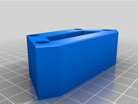
Feed both loose wires through the cable chain opening in the bed mount part and then replace the rubber grommet.
Use some short screws and nuts to secure the bed mount part to the bed.
Re-secure the print bed plate to the printer. Be careful with the angle of the wires where they attach to the underside of the bed. Avoid a sharp angle toward the back of the printer so that the solder joints are not under stress.
Feed the two loose wire connectors through the bottom section of the fan opening at the back of the printer.
Set the printer on it's back again.
Remove the bottom panel like before.
Mount the 40mm fan to the flat side of the shroud (not the side with the notch at the bottom).
Position the printer so that the upper-left screw hole for the rear fan is accessible by hanging just over the edge of your work table.
Feed the wires through the notch in the fan shroud and then line up the fan shroud with the original fan mounting holes on the back of the printer. Note that the notch should point down when the printer is upright.
While holding the fan shroud in place with one hand, use one of the original fan mounting screws to secure the upper-left corner (in relation to facing the back of the printer) of the fan shroud to the printer chassis.
Repeat the last step to secure the upper-right corner of the fan shroud.
Reconnect the bed heater and thermister connections to the circuit board.
Re-position and secure the bottom panel of the printer. When doing this take special care to make sure that the fan is not in contact with any wires. It is much closer to the circuit board and other wires than it was before. Use wire ties as needed.
Gently pull on the bed heater and thermister wires to take up excessive slack inside the printer. Note that the bed should move freely to both stop points without any pulling on the wires. If it does not, then you will need to open the printer back up again and find a different route for the wires.
Secure the fan chain adapter to the back of the printer with two screws. Be sure to not apply too much force as doing so could break the fan shroud since it is not supported from the other side.
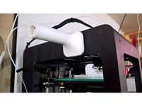
Attach cable chain links as needed for cable length.
There is absolutely no cutting or drilling required for this mod. This works with a few different cable chain models out there. I used https://www.thingiverse.com/thing:611593/ for the ends, but I am actually using a cable chain that a friend had printed for me while my printer was down that I do not know the origin of. I needed 10 links for my application. It would be a good idea to print a few more than 10 just to be on the safe side.
You will probably want to print the fan shroud with supports. If your printer does really long bridging well you may be able to get away with printing it upright without supports, but I did not try.
You will need to provide your own screws to mount the fan to the shroud and the fan opening chain adapter. 2 of the stock stock 40mm fan mounting screws can be used to mount the shroud to the back of the printer. You will also need to locate some screws (fairly short) and nuts to secure the bed mount part. I happened to have everything I needed in loose parts bins that I had around the hose so I do not know specifically what screws to recommend. You should print the parts and locate screws that will work before you try to stall the parts into the printer.
Installation instructions:
Note: Please only install this if you are comfortable working on mechanical and electronic devices. It should go without saying, but you are proceeding at your own risk. Be sure the printer is unplugged and cool before you begin.
Whenever handling wires be sure to not pull too hard on connectors. Also always be sure that all wires are clear when tightening any screw to avoid pinching the wire.
Do not over-tighten screws!
Tools required:
Phillips screw driver.
Something to cut wire ties.
Remove the 4 screws that hold the 40mm fan in place on the back of the printer. You could probably do this later, but I found it easier to do this first.
Set printer on it's back and remove the 6 screws that hold the bottom to the chassis. Take care to support the bottom plate when removing the last screw so that it does not free-fall. You can also rotate the bottom panel 90 degrees (with the circuit board toward the back of the printer) to avoid disconnecting anything.
Locate and disconnect the bed heater and bed thermister wires from the circuit board.
Clip any wire ties holding these two wires in place.
Carefully route the two loose wires through the hole in the top of the chassis. You may need to push the rubber grommet through the hole in order to get the bed heater wire connector through the hole.
Put the bottom plate back in place loosely with just a couple screws and the turn the printer upright again.
Pull the two loose cables through the hole in the top of the chassis until they are clear of falling back inside. Note If you had to displace the rubber grommet to get the wires out of the chassis, you can put it back in place now.
Remove the print bed surface. TIP: If you use a caliper to measure the height of all 4 corners it makes re-leveling the bed a little easier when the printer is reassembled.
Cut the wire tie holding the wires to the underside of the print bed,
Pop the rubber grommet out of the print bed and pull the two loose wires through the hole.
Feed both loose wires through the cable chain opening in the bed mount part and then replace the rubber grommet.
Use some short screws and nuts to secure the bed mount part to the bed.
Re-secure the print bed plate to the printer. Be careful with the angle of the wires where they attach to the underside of the bed. Avoid a sharp angle toward the back of the printer so that the solder joints are not under stress.
Feed the two loose wire connectors through the bottom section of the fan opening at the back of the printer.
Set the printer on it's back again.
Remove the bottom panel like before.
Mount the 40mm fan to the flat side of the shroud (not the side with the notch at the bottom).
Position the printer so that the upper-left screw hole for the rear fan is accessible by hanging just over the edge of your work table.
Feed the wires through the notch in the fan shroud and then line up the fan shroud with the original fan mounting holes on the back of the printer. Note that the notch should point down when the printer is upright.
While holding the fan shroud in place with one hand, use one of the original fan mounting screws to secure the upper-left corner (in relation to facing the back of the printer) of the fan shroud to the printer chassis.
Repeat the last step to secure the upper-right corner of the fan shroud.
Reconnect the bed heater and thermister connections to the circuit board.
Re-position and secure the bottom panel of the printer. When doing this take special care to make sure that the fan is not in contact with any wires. It is much closer to the circuit board and other wires than it was before. Use wire ties as needed.
Gently pull on the bed heater and thermister wires to take up excessive slack inside the printer. Note that the bed should move freely to both stop points without any pulling on the wires. If it does not, then you will need to open the printer back up again and find a different route for the wires.
Secure the fan chain adapter to the back of the printer with two screws. Be sure to not apply too much force as doing so could break the fan shroud since it is not supported from the other side.
Attach cable chain links as needed for cable length.
Similar models
thingiverse
free

Slim X Axis Cable Chain Hotend Mount for Ender 3 using Satsana Remix for Ender 3V2 Fan Shroud by Vyperious
...ded strength vs cost savings is promising.
my first remix, let me know how i did. also credit due to the above mentioned. enjoy!
thingiverse
free

A30M Extruder Cable Manager by cginaz
...angs down low enough to get a cable tie through the smaller holes at the bottom of the print to secure the cables out of the way.
thingiverse
free

BLV mgn bed cable sleeve mount
...x10 screws and m5 hammer nuts to fix the mounts to the extrusions
m3x8 and m3 nuts to secure the wires on at the bed and the back
thingiverse
free

Anet A6 - Bed mount for 10x10 cable by DarthVader911
...o-iiqp2dtl-42c1-r4k9pzps-1tbzhl_odo5i15t2cztnya-k2yqwdlhrvnsuh_vwfi8tcfaovkt8ben5yb_gmhiqygvjvmcra5argl4mjfgshoqohsoxsuqvca2mg4lk
thingiverse
free
Heat Bed Cable Chain Mounts for Printrbot Simple Metal for X Axis Upgrade by Twolter66
... chain links.
i had to solder new wires onto the heat plate because they were not long enough to accommodate the length of chain.
thingiverse
free

Y axis cable chain horizontal mount for Wanhao Di3 / Monoprice Maker Select v2.1 by xenz
... then this mount isn't for you.
also, the rear mount do extended the printer about 8cm in length. measure before you print !!
thingiverse
free
Lack Enclosure Table Grommet by littleab
...look to both the top and bottom of the grommet.
to insulate the hole with the wires in it, just press some foam into the grommet.
thingiverse
free

Noctua 60mm x 25mm Fan Cover Shroud by Skoopsy
...er 3 pro psu.
there is no hole for the fan wire, as i routed the fan wire through an unused fan bolt hole back into the psu case.
thingiverse
free

RedCat Gen 7 Front ESC/Receiver Mount by SimpleSine
...e post backward. you need to remove the battery tray to do this. the mount just rests on the top of the screws still very secure.
thingiverse
free

Anet A6 Bed Y-axis Cable Chain (front mount) by jbhugh
...table, but there is a frame screw close by on the a6 that could be made to work with a remix of the end piece (male_end_mod.stl).

Monoprice
thingiverse
free

Display frame for Monoprice MP10
...display frame for monoprice mp10
thingiverse
display frame for monoprice mp10
thingiverse
free

Bridge covers Monoprice MP10
...bridge covers monoprice mp10
thingiverse
bridge covers monoprice mp10
thingiverse
free
Monoprice Coin by Peyton_Guyot
...monoprice coin by peyton_guyot
thingiverse
print this!
thingiverse
free
Voxel Monoprice spool holder by avalero
...voxel monoprice spool holder by avalero
thingiverse
voxel monoprice spool holder
thingiverse
free
Monoprice select mini knob by BramRausch
...monoprice select mini knob by bramrausch
thingiverse
this is a replacement knob for the monoprice select mini.
thingiverse
free

Monoprice 3d printer hook by dmitriyf
...monoprice 3d printer hook by dmitriyf
thingiverse
this is an attachment to monoprice select 3d printer v2
thingiverse
free
monoprice ultimate spool mount by death4u
...older by danmannert to monoprice ultimate 3d printer. it clips into the slot on the top of the printer for the optional enclosue.
thingiverse
free
Monoprice Mini Delta Foot
...a foot for a monoprice mini delta. it helps to increase airflow under the printer. it also helps to reduce the volume of the fan.
thingiverse
free
Monoprice Select Mini Fan Guard
...y fan protection. this is an essential upgrade.
used it on the monoprice select mini pro (from www.3dprinthings.be).
perfect fit!
thingiverse
free

Monoprice Cable Tie Mount
... but had to cut down the straps a bit to make them work. designed a quick mount that fits the full strap, item 6457 on monoprice.
Route
turbosquid
$10

ROUTES~1.3DS
... available on turbo squid, the world's leading provider of digital 3d models for visualization, films, television, and games.
turbosquid
$46

Task Chair - Route
...del task chair - route for download as max, 3ds, fbx, and obj on turbosquid: 3d models for games, architecture, videos. (1644066)
turbosquid
$10

ROUTES~1.DXF
... available on turbo squid, the world's leading provider of digital 3d models for visualization, films, television, and games.
turbosquid
$10

ROUTES~1.LWO
... available on turbo squid, the world's leading provider of digital 3d models for visualization, films, television, and games.
3d_export
$65

eighth route army
...eighth route army
3dexport
simple rendering of the scene file
3d_export
$65

eighth route army
...eighth route army
3dexport
simple rendering of the scene file
turbosquid
$6
![Alternative route [traffic signal]](/t/13301445.jpg)
Alternative route [traffic signal]
... model alternative route [traffic signal] for download as max on turbosquid: 3d models for games, architecture, videos. (1199677)
3ddd
$1

Route nationale 7
...route nationale 7
3ddd
дорожный знак
inspiration fro road signs of the nationale 7
3d_export
$6

MDF Routed Beds 3D Model
...mdf routed beds 3d model
3dexport
bed
mdf routed beds 3d model ashvathnarayana 62550 3dexport
turbosquid
$5

Route to be used by pedal cycles only
... available on turbo squid, the world's leading provider of digital 3d models for visualization, films, television, and games.
40Mm
turbosquid
$10

40MM Bullet
... available on turbo squid, the world's leading provider of digital 3d models for visualization, films, television, and games.
turbosquid
$49
40mm Vickers-Terni
... free 3d model 40mm vickers-terni for download as lwo and obj on turbosquid: 3d models for games, architecture, videos. (1260063)
turbosquid
$3
40mm grenade M9XX
...y free 3d model 40mm grenade m9xx for download as obj and fbx on turbosquid: 3d models for games, architecture, videos. (1408150)
turbosquid
$3

40mm grenade M3XX
...y free 3d model 40mm grenade m3xx for download as obj and fbx on turbosquid: 3d models for games, architecture, videos. (1408145)
turbosquid
$3
40mm grenade M1XX
...y free 3d model 40mm grenade m1xx for download as obj and fbx on turbosquid: 3d models for games, architecture, videos. (1408144)
turbosquid
$8

40mm Smith & Wesson
... available on turbo squid, the world's leading provider of digital 3d models for visualization, films, television, and games.
turbosquid
free
Free 40mm grenade M433
...e 3d model free 40mm grenade m433 for download as obj and fbx on turbosquid: 3d models for games, architecture, videos. (1404768)
turbosquid
$98

40mm 6G30 grenade launcher
... available on turbo squid, the world's leading provider of digital 3d models for visualization, films, television, and games.
turbosquid
$10

Famas G2 M203 40mm.
... available on turbo squid, the world's leading provider of digital 3d models for visualization, films, television, and games.
turbosquid
free
40mm Bofors TNT-11606
... available on turbo squid, the world's leading provider of digital 3d models for visualization, films, television, and games.
Select
3ddd
$1

TUBADZIN SELECT
...max 2014, 2011.
fbx 2014, 2013, 2011,
obj
_____________________________________http://www.tubadzin.pl/en/collection/324
3ddd
$1
Плитка Selection
... supergres , плитка
плитка selection - supergres ceramiche
turbosquid
$15
Christmas Selection
...royalty free 3d model christmas selection for download as fbx on turbosquid: 3d models for games, architecture, videos. (1696333)
turbosquid
$39

Vases selection
... available on turbo squid, the world's leading provider of digital 3d models for visualization, films, television, and games.
turbosquid
free

SELECTIVE RACKING SYSTEM
...yalty free 3d model selective racking system for download as on turbosquid: 3d models for games, architecture, videos. (1282512)
turbosquid
$10
Hansgrohe ShowerTablet Select
...ee 3d model hansgrohe showertablet select for download as max on turbosquid: 3d models for games, architecture, videos. (1336955)
turbosquid
$29
Chill selectional sofa
...odel chill selectional sofa for download as max, obj, and fbx on turbosquid: 3d models for games, architecture, videos. (1465691)
3ddd
free

Lunaria - Nova, ASA Selection
... asa selection , dried flowers
ветка лунарии в вазе nova, asa selection
3ddd
$1

inno SELECT SLIM chair
...inno select slim chair
3ddd
inno
high detailed inno select slim chair
turbosquid
$29

Select Chaise Lounge
... available on turbo squid, the world's leading provider of digital 3d models for visualization, films, television, and games.
V2
3d_export
free
Lamp v2
...lamp v2
3dexport
lamp v2 with solar panel
3d_export
$5

hammerhead v2
...hammerhead v2
3dexport
razer hammerhead v2 headphones, modeled in cinema 4d, render in corona
3d_export
$5

manometer v2
...manometer v2
3dexport
3d_export
$5
potato v2
...potato v2
3dexport
turbosquid
$52

Lifebuoys v2
...squid
royalty free 3d model lifebuoys v2 for download as fbx on turbosquid: 3d models for games, architecture, videos. (1560870)
turbosquid
$2

Mask v2
...turbosquid
royalty free 3d model mask v2 for download as stl on turbosquid: 3d models for games, architecture, videos. (1527741)
turbosquid
free
Flashlight V2
...d
free 3d model flashlight v2 for download as , obj, and fbx on turbosquid: 3d models for games, architecture, videos. (1663559)
turbosquid
$29
Thanos v2
...
royalty free 3d model thanos v2 for download as ztl and obj on turbosquid: 3d models for games, architecture, videos. (1651077)
turbosquid
$29
Titan v2
...d
royalty free 3d model titan v2 for download as ztl and obj on turbosquid: 3d models for games, architecture, videos. (1540228)
turbosquid
$29
Frieza v2
...
royalty free 3d model frieza v2 for download as ztl and obj on turbosquid: 3d models for games, architecture, videos. (1701238)
Cable
3d_export
free

Cables
...cables
3dexport
cables for your purposes
3d_export
free
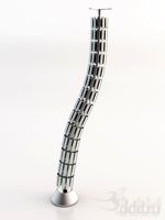
cable belt for cable organization
...ze your cables in 3d printers. it will bend only to one direction. the area to put the cables per piece is aprox. 1,6cmx2,6cmx1cm
3d_ocean
$16
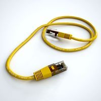
Ethernet Cable
...ethernet cable
3docean
cable computer electronics ethernet internet network connected
ethernet cable 3d model
3d_export
$65

cable
...cable
3dexport
simple rendering of the scene file
turbosquid
$14

Cable
...l cable for download as ma, max, fbx, 3ds, gltf, obj, and stl on turbosquid: 3d models for games, architecture, videos. (1631358)
3ddd
$1
Cable Cover
...cable cover
3ddd
кабель
vertebra passacavo - cable cover
max + vray 2.20.03
3d_export
$15
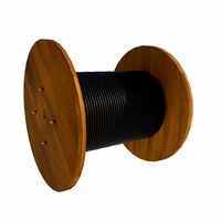
Cable reel
...without cable. textures 4k 4096x4096 targa, png, jpeg.<br>number of polygons without cable: 2896<br>with cable: 35328
3d_export
$7

short cable
...short cable
3dexport
rubber cord. very detailed. cable thickness: 2.55 mm total length: 55mm
3d_export
$5

USB CABLE
...usb cable
3dexport
turbosquid
$30
Cable Reels
...osquid
royalty free 3d model cable reels for download as fbx on turbosquid: 3d models for games, architecture, videos. (1439507)
Mini
turbosquid
$10
Mini Mini Luceplan
...
royalty free 3d model mini mini luceplan for download as max on turbosquid: 3d models for games, architecture, videos. (1227359)
3d_ocean
$39

Mini Cooper
...mini cooper
3docean
cabrioler cooper mini
mini cooper cabrioler
3d_export
$30

Mini lathe
...mini lathe
3dexport
mini lathe
3d_export
$5

mini mouse
...mini mouse
3dexport
mini mouse
3d_export
$5

mini house
...mini house
3dexport
mini house
3d_export
free

Mini Mecha
...mini mecha
3dexport
concept of mini mecha
3d_ocean
$20
Mini Gun
...mini gun
3docean
gatling gun gun machine gun mini gun weapon
model of a mini gatling gun.
3ddd
free

Herve mini
... кофейный , herve
http://www.mobiliavenanti.it/ru/products/hervè-mini
3d_export
$5
mini wall
...mini wall
3dexport
mini wall for living room
3d_export
$5

mini bank
...mini bank
3dexport
mini bank 3d model
Re
3ddd
$1
RES 10_8
...res 10_8
3ddd
res , дверь
производитель res модель 10.8
turbosquid
$7

Re
... available on turbo squid, the world's leading provider of digital 3d models for visualization, films, television, and games.
design_connected
$18
Re-trouvé
...re-trouvé
designconnected
emu group re-trouvé chairs computer generated 3d model. designed by patricia urquiola.
design_connected
$16

Re-turned
...
photo-realistic 3d models of the re-turned table accessories from beller for 3d architectural and interior design presentations.
3ddd
free
дверь RES WAVE
... дверь , карим рашид
производитель res италия модель wave
turbosquid
$1

Table Re
...ree 3d model table re for download as ma, obj, fbx, and blend on turbosquid: 3d models for games, architecture, videos. (1233574)
3ddd
$1

Do-lo-Res
... угловой
диван фабрика do-lo-res компонуется из отдельных боксов, разнообразных размеров и тканей.
design_connected
$16
Re-trouvé Tables
...re-trouvé tables
designconnected
emu group re-trouvé tables computer generated 3d model. designed by urquiola, patricia.
design_connected
$11

Re-flect pendant
...re-flect pendant
designconnected
steng licht re-flect pendant computer generated 3d model. designed by e27 berlin.
design_connected
$11

Re-flect wall
...re-flect wall
designconnected
steng licht re-flect wall computer generated 3d model. designed by e27 berlin.
Fan
3d_export
$5
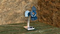
fan
...fan
3dexport
fan 3d model, table fan, fan, electric fan, ventilator
archibase_planet
free

Fan
...fan
archibase planet
fan large fan
fan out n260707 - 3d model for interior 3d visualization.
archibase_planet
free
Fan
...fan
archibase planet
fan ceiling fan ventilator
fan stealth n300615 - 3d model (*.gsm+*.3ds) for interior 3d visualization.
3d_export
$15

fan
...fan
3dexport
is an ancient fan
3ddd
$1
Fan-C-Fan by marco gallegos
...n-c-fan by marco gallegos
3ddd
вентилятор , marco gallegos
fan-c-fan by marco gallegos
3d_export
$10
fan
...fan
3dexport
a detailed fan designed for home or space blowing is now available for only 19.99!
turbosquid
$1
Fan
...fan
turbosquid
free 3d model fan for download as on turbosquid: 3d models for games, architecture, videos. (1427865)
turbosquid
$14

Fan
...fan
turbosquid
royalty free 3d model fan for download as on turbosquid: 3d models for games, architecture, videos. (1415642)
3ddd
$1

Светильник Fan
...светильник fan
3ddd
fan , italamp
светильник fan, производитель italamp
turbosquid
$25

Fan
...fan
turbosquid
royalty free 3d model fan for download as c4d on turbosquid: 3d models for games, architecture, videos. (1483246)
Bed
3ddd
$1

bed
...bed
3ddd
bed , постельное белье
bed
3ddd
$1

bed
...bed
3ddd
bed , постельное белье
bed
3ddd
$1
bed
...bed
3ddd
bed , постельное белье
bed
3ddd
$1

bed
...bed
3ddd
bed , постельное белье
bed
3ddd
$1

bed
...bed
3ddd
bed , постельное белье
bed
3ddd
$1

bed
...bed
3ddd
bed , постельное белье
bed
3ddd
free
bed
...bed
3ddd
bed , постельное белье
bed
3ddd
free

bed
...bed
3ddd
bed , постельное белье
bed
3ddd
$1
Bed
...bed
3ddd
bed , постельное белье , постель
bed
3d_export
$7

bed adairs bed
...rs bed
3dexport
bed adairs bed in modern style. if you want a smoother surface, please turn on turbosmooth in the modifier list.
Hole
design_connected
$9
Hole
...hole
designconnected
zeritalia hole shelves and storage computer generated 3d model. designed by derin design.
3ddd
$1

Magic hole
...magic hole
3ddd
magic
дизайнерское кресло magic hole
3d_export
free

black hole
...black hole
3dexport
3d rendering black hole in blender 2.9
3ddd
$1

Magic Hole
...magic hole
3ddd
philippe starck
magic hole - дизайн philippe starck (2010)
turbosquid
$4

Black Hole
...squid
royalty free 3d model black hole for download as blend on turbosquid: 3d models for games, architecture, videos. (1606724)
turbosquid
$5

security hole
...yalty free 3d model security hole for download as 3dm and max on turbosquid: 3d models for games, architecture, videos. (1669645)
turbosquid
$32
hole punch
... 3d model hole punch for download as 3ds, obj, fbx, and blend on turbosquid: 3d models for games, architecture, videos. (1230702)
3d_export
$10
Black hole
...black hole
3dexport
a minimalist representation of a singularity
turbosquid
$50

Worm Hole
... available on turbo squid, the world's leading provider of digital 3d models for visualization, films, television, and games.
turbosquid
$30

15 Hole
... available on turbo squid, the world's leading provider of digital 3d models for visualization, films, television, and games.