Thingiverse
Modular Electronics Enclosure by MyFunctionalDesigns
by Thingiverse
Last crawled date: 3 years, 3 months ago
Final Validation Prints have Started
I am working on an enclosure to house my electronics. As I know things change, so I have gone for a very modular approach.
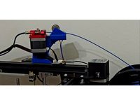
My plan is to house a DIN rail for mounting my power supplies (24V, 12V, and 5V) as well as relays to control certain items (Ex: mains powered bed).
During the design I have tried to keep everything as clean as possible, including hiding all screws from view. This makes some of the prints, such as the accent, a bit trickier, but I think it is worth it in the end.
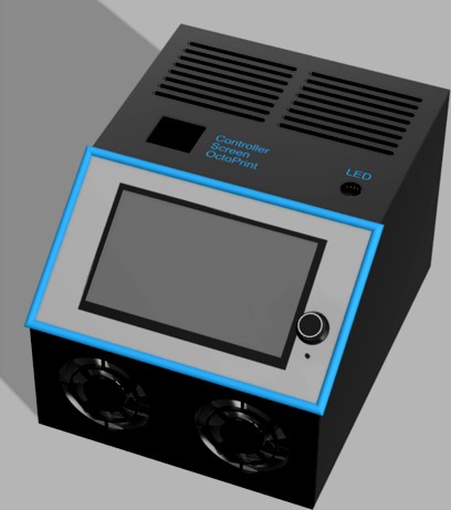
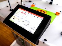
The dimensions are 230 mm wide, 190 mm tall, and 290 mm deep. The screen is at a 35 degree angle to provide easy visibility.
For now I am adding the Fusion renderings as I am still working on making sure everything fits together. As each piece is completed the files will be added so this may look very incomplete for a while.
In the end to make it easier to do remixes or additional mounts, I will be providing both STL and Fusion 360 source files.
Screenshot Descriptions
The design you are looking at is almost complete as I am verifying joints and part fits for items that go in the initial panels. Most are still in the mail, so it is taking a while.
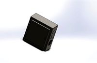
The rendering is 3 colors, with the body in black, the screen border in grey, and an accent color in blue. The case is designed for a 2-3 color look, although you can go hog wild when you print your version.
I have the new Big Tree Tech TFT70 on order, so this case will fit large amounts of stuff as you can see. The TFT70 is 200mm x 100mm.
The front has dual 80mm fans, and the top has room for 3 SD card extension mounts (Screen, Controller, and Pi). It also has a spot where I plan to put a switch to turn my LEDs on and off. Text is recessed .5mm with seperate bodies to allow dual color printing.
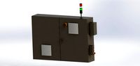
On the back panel I have placed GX16 connectors for most of the wiring. There is room for 3 USB ports (1 per component, Keystone Slot) and a hardwired network cable (Keystone Slot) for the Pi for those that prefer that over WiFi . There is also a standard power input and switch, along with a output for the mains powered bed controlled via a relay. A remix to put an XT-60 connector on the back would be very quick and simple, and I might have that as part of the base panels when I get everything ready.
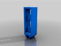
Finally the inside view shows you the mounting rails for your internals, as well as holes in the bottom for securing additional items. The center rail is the perfect height for those that want to mount a DIN rail to mount items to.
General Design
I have used parameter based design as much as possible (mounts excluded as they are one-offs, usually only based on parameters for mount holes) to ensure that everything lines up correctly. Each panel is designed to be customized as needed, so you can make minor (or major) changes to fit your needs easily.
Remixing and Custom Mounts were the plan from the start, so once it is out, have at it.
Main components that should not require customization include:
Bottom Panel
Left Panel
Right Panel
Accent Border
Main components that may require customization include (ideas for custom items in sub lists):
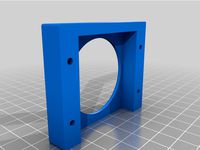
Front Panel
Single or Dual Fans
Vents Only
Top Panel
Variable number of SD Card slots
Vents Only
LED Switch present
Screen Panel
Will require 2 panels per screen, one floating (what you see) and one back for mounting screen to
Rear Panel, Split into Left and Right sides (one for power, one for connections)
Power connectors (based upon your needs)
Control Wire Connectors
Fan Connectors
Lighting Connectors
Network Connections
USB Connections
Mains Power Cover Safety Item
A panel to cover up your 110/220v mains wiring so you don't accidentally touch it when opening your case.
Electronics Mounts
A new mount needs to be added for each piece of equipment that you want to add to the case.
Assembly Instructions
There are a few unique parts to this, so I will document how they are intended to go together with a complete parts list for the base case, along with a parts list for the components that I have chosen for my case.
Mount Rails
There are multiple mount rails available with 3 on both the left and right panel, as well as 3 in the bottom panel. Once final spacing is completed, I will list all the measurements here.
Tentative spacing is as follows:
Bottom/Base panel has holes that are 50mm on center (from wall to center, or center to center), 3 rows of 25 holes.
Sides are 75mm on center, with the first row being 17mm above the base panel. The bottom 2 rows have 25 holes, and the top one has 15.
Case Parts Requirements
Parts for Assembly:
28mm x 3mm piano wire, 8 pieces
Glue (optional, secure wire in sides)
M3 screw inserts, holes are sized for Ruthex threaded inserts
M3x8 screw, 5
M3x20 screw, 2
Parts for attaching Mounts:
M3 screw inserts, holes are sized for Ruthex threaded inserts
M3x8 screws
You can also use M3x10 screws along with some washers. This may provide a more secure mount as the washer spreads the load slightly against the material by having a larger area of contact.
Shopping List
Here are some parts that I have used in my designs. To prevent remixing, use parts that use the same mount patterns.
Chosen Electronics:
BTT SKR 1.4 Turbo
BTT TFT70
Initial Case
M3 Screw Inserts
DIN Rail
DIN mounted 12v Power for fans
2 BeQuiet 80mm PWM Pure Wings 2 Fans
Temperature based fan controller
7 GX16 Connectors, 4 Pin
GX16 Connector, 5 Pin for BL Touch
Power Switch
AC Supply Socket, Male
Supply Socket, Female for power to Bed
Supply Cable to Bed, one end cut and wired to bed.
2 USB Keystone for Screen + Controller
Keystone Cover (for Pi slots, future upgrade for me)
2 SD Card Extension for Screen + Controller
Rubber Feet
USB 90 degree turn for screen to access USB slot
XT 60 Socket (See Note 1)
a short USBB => USBA cable for the controller
A short USB3 A=>A cable for the screen
A switch for LED lights (TBD)
Wiring and sleeving for a new wire harness
Note 1: Prior to upgrading my power, I used the stock PS in its original location to feed power to my electronics via a 24V cable. This used an XT60 socket inbound to the controller. I then used the Supply Socket outward towards the heated bed which also provided an additional grounding point to the frame.
Mains Heated Bed / Power Upgrade (See Note 1):
DIN mounted 24v Power for Controller
24V Solid State Relay to control 220V, TBD
Silicone Bed Heater, TBD
Aluminum Bed, TBD
Note 1: I have not yet completed this upgrade, so the list may change.
To add a Raspberry Pi with Octoprint (See Note 1):
A Raspberry Pi
DIN mounted 5v Power, 3A or 6A (See Note 2)
USB Keystone
RJ45 Keystone for hard wired networking
SD Card Extension
A short USB3 A=>A cable
A short USBC cable to provide power to the Pi. Will cut and wired to the power supply.
A short network cable
Note 1: I have not yet completed this upgrade, so the list may change.
Note 2: Power supply based upon if you are driving LEDs on 5V or not
Print Settings
You know your printer best, so pick what you feel is right. That said, here are my general settings for prints. Certain parts may need unique orientations to fit on your print bed, which might also require different supports.
Slicer: Cura 4.6.1
Material: PLA
Infill: 20%
Supports: Tree
Bed Adhesion: Rafts as needed
I am working on an enclosure to house my electronics. As I know things change, so I have gone for a very modular approach.
My plan is to house a DIN rail for mounting my power supplies (24V, 12V, and 5V) as well as relays to control certain items (Ex: mains powered bed).
During the design I have tried to keep everything as clean as possible, including hiding all screws from view. This makes some of the prints, such as the accent, a bit trickier, but I think it is worth it in the end.
The dimensions are 230 mm wide, 190 mm tall, and 290 mm deep. The screen is at a 35 degree angle to provide easy visibility.
For now I am adding the Fusion renderings as I am still working on making sure everything fits together. As each piece is completed the files will be added so this may look very incomplete for a while.
In the end to make it easier to do remixes or additional mounts, I will be providing both STL and Fusion 360 source files.
Screenshot Descriptions
The design you are looking at is almost complete as I am verifying joints and part fits for items that go in the initial panels. Most are still in the mail, so it is taking a while.
The rendering is 3 colors, with the body in black, the screen border in grey, and an accent color in blue. The case is designed for a 2-3 color look, although you can go hog wild when you print your version.
I have the new Big Tree Tech TFT70 on order, so this case will fit large amounts of stuff as you can see. The TFT70 is 200mm x 100mm.
The front has dual 80mm fans, and the top has room for 3 SD card extension mounts (Screen, Controller, and Pi). It also has a spot where I plan to put a switch to turn my LEDs on and off. Text is recessed .5mm with seperate bodies to allow dual color printing.
On the back panel I have placed GX16 connectors for most of the wiring. There is room for 3 USB ports (1 per component, Keystone Slot) and a hardwired network cable (Keystone Slot) for the Pi for those that prefer that over WiFi . There is also a standard power input and switch, along with a output for the mains powered bed controlled via a relay. A remix to put an XT-60 connector on the back would be very quick and simple, and I might have that as part of the base panels when I get everything ready.
Finally the inside view shows you the mounting rails for your internals, as well as holes in the bottom for securing additional items. The center rail is the perfect height for those that want to mount a DIN rail to mount items to.
General Design
I have used parameter based design as much as possible (mounts excluded as they are one-offs, usually only based on parameters for mount holes) to ensure that everything lines up correctly. Each panel is designed to be customized as needed, so you can make minor (or major) changes to fit your needs easily.
Remixing and Custom Mounts were the plan from the start, so once it is out, have at it.
Main components that should not require customization include:
Bottom Panel
Left Panel
Right Panel
Accent Border
Main components that may require customization include (ideas for custom items in sub lists):
Front Panel
Single or Dual Fans
Vents Only
Top Panel
Variable number of SD Card slots
Vents Only
LED Switch present
Screen Panel
Will require 2 panels per screen, one floating (what you see) and one back for mounting screen to
Rear Panel, Split into Left and Right sides (one for power, one for connections)
Power connectors (based upon your needs)
Control Wire Connectors
Fan Connectors
Lighting Connectors
Network Connections
USB Connections
Mains Power Cover Safety Item
A panel to cover up your 110/220v mains wiring so you don't accidentally touch it when opening your case.
Electronics Mounts
A new mount needs to be added for each piece of equipment that you want to add to the case.
Assembly Instructions
There are a few unique parts to this, so I will document how they are intended to go together with a complete parts list for the base case, along with a parts list for the components that I have chosen for my case.
Mount Rails
There are multiple mount rails available with 3 on both the left and right panel, as well as 3 in the bottom panel. Once final spacing is completed, I will list all the measurements here.
Tentative spacing is as follows:
Bottom/Base panel has holes that are 50mm on center (from wall to center, or center to center), 3 rows of 25 holes.
Sides are 75mm on center, with the first row being 17mm above the base panel. The bottom 2 rows have 25 holes, and the top one has 15.
Case Parts Requirements
Parts for Assembly:
28mm x 3mm piano wire, 8 pieces
Glue (optional, secure wire in sides)
M3 screw inserts, holes are sized for Ruthex threaded inserts
M3x8 screw, 5
M3x20 screw, 2
Parts for attaching Mounts:
M3 screw inserts, holes are sized for Ruthex threaded inserts
M3x8 screws
You can also use M3x10 screws along with some washers. This may provide a more secure mount as the washer spreads the load slightly against the material by having a larger area of contact.
Shopping List
Here are some parts that I have used in my designs. To prevent remixing, use parts that use the same mount patterns.
Chosen Electronics:
BTT SKR 1.4 Turbo
BTT TFT70
Initial Case
M3 Screw Inserts
DIN Rail
DIN mounted 12v Power for fans
2 BeQuiet 80mm PWM Pure Wings 2 Fans
Temperature based fan controller
7 GX16 Connectors, 4 Pin
GX16 Connector, 5 Pin for BL Touch
Power Switch
AC Supply Socket, Male
Supply Socket, Female for power to Bed
Supply Cable to Bed, one end cut and wired to bed.
2 USB Keystone for Screen + Controller
Keystone Cover (for Pi slots, future upgrade for me)
2 SD Card Extension for Screen + Controller
Rubber Feet
USB 90 degree turn for screen to access USB slot
XT 60 Socket (See Note 1)
a short USBB => USBA cable for the controller
A short USB3 A=>A cable for the screen
A switch for LED lights (TBD)
Wiring and sleeving for a new wire harness
Note 1: Prior to upgrading my power, I used the stock PS in its original location to feed power to my electronics via a 24V cable. This used an XT60 socket inbound to the controller. I then used the Supply Socket outward towards the heated bed which also provided an additional grounding point to the frame.
Mains Heated Bed / Power Upgrade (See Note 1):
DIN mounted 24v Power for Controller
24V Solid State Relay to control 220V, TBD
Silicone Bed Heater, TBD
Aluminum Bed, TBD
Note 1: I have not yet completed this upgrade, so the list may change.
To add a Raspberry Pi with Octoprint (See Note 1):
A Raspberry Pi
DIN mounted 5v Power, 3A or 6A (See Note 2)
USB Keystone
RJ45 Keystone for hard wired networking
SD Card Extension
A short USB3 A=>A cable
A short USBC cable to provide power to the Pi. Will cut and wired to the power supply.
A short network cable
Note 1: I have not yet completed this upgrade, so the list may change.
Note 2: Power supply based upon if you are driving LEDs on 5V or not
Print Settings
You know your printer best, so pick what you feel is right. That said, here are my general settings for prints. Certain parts may need unique orientations to fit on your print bed, which might also require different supports.
Slicer: Cura 4.6.1
Material: PLA
Infill: 20%
Supports: Tree
Bed Adhesion: Rafts as needed
Similar models
thingiverse
free
Raspberry Pi headless server case
...al)
1x 6mm power switch (optional)
1x 40x40x10mm 5v fan (optional)
3-pin female connector
wires (suggested: red 10cm, black 10cm)
thingiverse
free

Kossel XL 2020 USB B panel by rmoro
... the panel to the printer. the photos also show the controller board with the usb connector that came off and the repaired board.
thingiverse
free

Power Functions PWM controller by AnnDee
...tor with cable
power functions connector with cable (you can also use my printfile for the connector)
4 screws m2 x 18 (iso 4762)
thingiverse
free

Remixed Left Case by pigaro
.... i had the opposite problem on the right side case. the screws protruded too far, so i made some cylinders to offset the screws.
thingiverse
free

Rear Anet A8 LCD mount for Raspberry Pi 3 by halfluck
...nnector wasn't sticking up out of the top and added 3mm width so that the usb connectors clear the lcd ribbon cable connector
thingiverse
free
USB socket case by T_Hambush
...a socket, which was mounted on a bit of stripboard. i have attached it to the 5v rail of an atx psu and it powers a raspberry pi.
thingiverse
free

Raspberry Pi 4 case with built-in power supply by aeberbach
...upply is doing how to build this safely.
longer blog post about this: https://aeberbach.github.io/posts/2019-10-09-rpi4-psu-case
thingiverse
free
Lack PowerSupply Mount by niget2002
...seem to really add much heat to the enclosure.
you will need 4 of the power supply mounts and one of each of the other two parts.
thingiverse
free

N64 controller panel-mount connector by jamesglanville
... easy source of the panel mount connectors. this one works well, using just a printed part, and some pieces of thick copper wire.
thingiverse
free
7inch PanelDue screen case for BigBox by robas
...s.
parts used:
9x m3x6 hex socket self tapping screw
1x 20cm 40pin gpio ribbon cable
2x 40pin 2.54mm male single row header strip
Myfunctionaldesigns
thingiverse
free
Ender 5 Spool Mount by MyFunctionalDesigns
...ted to the top rail on an ender 5.
designed to work with my spool mounted runout sensor:https://www.thingiverse.com/thing:4718423
thingiverse
free
Spool Mounted Runout Sensor by MyFunctionalDesigns
...le span) that mounts to the ender 5 filament arm.
designed together with my spool mount:https://www.thingiverse.com/thing:4718422
thingiverse
free

MicroSwiss Backplate for Ender 5 by MyFunctionalDesigns
...se this as a guide, but please test your designs to make sure they work.
the stl here is only because thingiverse requires it. :)
thingiverse
free

Runout Sensor for 2020 rails by MyFunctionalDesigns
...r switch and some wire with a plug to get this up and running.
fusion 360 file provided in case anyone wants to remix further. :)
thingiverse
free

Hero Me Gen 5: Ender 5 MicroSwiss Direct Drive Gantry Adapter by MyFunctionalDesigns
... this one.
it's a small part that makes the hero me gen 5 system work on the microswiss direct drive for the ender 5. yay! :d
thingiverse
free
Ender5 Extruder Arm M4 with filament runout sensor mount by TalFeiner
...runout sensor for 2020 railsas well, which published by myfunctionaldesigns so i just added a place to mount it...
Enclosure
3d_export
free
electrical enclosure
...l enclosure where electrical devices like (relays, contactors, busbars ) are kept in order to protect from hazardous environment.
turbosquid
$100
GPU Enclosure
...yalty free 3d model gpu enclosure for download as obj and stl on turbosquid: 3d models for games, architecture, videos. (1381061)
3d_export
$5
Electrical Enclosure
...ed. also has tower lights attaced on the top.<br>file format that are available:<br>.step<br>.obj<br>.stl
archive3d
free
Enclosure 3D Model
...closure 3d model
archive3d
shower enclosure-acquarius- 3d model for interior 3d visualization.
archive3d
free
Enclosure 3D Model
...enclosure 3d model
archive3d
shower enclosure-omega- 3d model for interior 3d visualization.
archive3d
free
Enclosure 3D Model
...enclosure 3d model
archive3d
shower enclosure-vega - 3d model for interior 3d visualization.
archive3d
free
Enclosure 3D Model
...enclosure 3d model
archive3d
shower enclosure-zenith - 3d model for interior 3d visualization.
turbosquid
$20
shower enclosure
... available on turbo squid, the world's leading provider of digital 3d models for visualization, films, television, and games.
turbosquid
$14
Dumpster Enclosure
... available on turbo squid, the world's leading provider of digital 3d models for visualization, films, television, and games.
turbosquid
$25
3d printer enclosure
... model 3d printer enclosure for download as ipt, skp, and fbx on turbosquid: 3d models for games, architecture, videos. (1634310)
Modular
3ddd
$1
MODULAR
...modular
3ddd
modular , врезной свет
modular потолочные светильники
3ddd
$1
Modular Spock
...modular spock
3ddd
modular
modular spock
3ddd
$1
MODULAR / Spock
...modular / spock
3ddd
modular
modular/spock
design_connected
$7
Modular
...modular
designconnected
emmemobili modular shelves and storage computer generated 3d model. designed by ferruccio laviani.
3ddd
$1
Modular spock
...modular spock
3ddd
modular
spock wall led
turbosquid
$25
Modular sofa Angelo Cappellini Modular
...a angelo cappellini modular for download as max, fbx, and obj on turbosquid: 3d models for games, architecture, videos. (1570923)
turbosquid
$15
Modular sofa Angelo Cappellini Modular
...a angelo cappellini modular for download as max, fbx, and obj on turbosquid: 3d models for games, architecture, videos. (1570304)
3ddd
$1
Modular 2FLAT2C
...modular 2flat2c
3ddd
modular
modularhttp://www.supermodular.com/
3d_export
free
Modular walls
...modular walls
3dexport
modular walls for playing without materials and textures
3ddd
$1
Modular / Lighting Juliette
...modular / lighting juliette
3ddd
modular
modular lighting juliette
Electronics
turbosquid
$1

electron
...urbosquid
royalty free 3d model electron for download as max on turbosquid: 3d models for games, architecture, videos. (1157488)
turbosquid
$50

electronic
...
royalty free 3d model electronic for download as max and obj on turbosquid: 3d models for games, architecture, videos. (1289427)
turbosquid
$40

Electron
... available on turbo squid, the world's leading provider of digital 3d models for visualization, films, television, and games.
3d_ocean
$8
Electronic game
...electronic game
3docean
electronic games nu pogody wait a minute well
electronic game “well, wait a minute”, “nu pogody”
3ddd
$1
Brilux Electronic
...brilux electronic
3ddd
подвес. brilux electronic. польша. материалы настроены.
3d_export
free

electronic shop
...lectronic shop with high quality interior and exterior. it has tvs smartphone play station printer and many more electronic item.
3ddd
$1

Термостаты OJ Electronics
...ермостаты oj electronics
3ddd
oj electronics , термостат
термостаты фирмы oj electronics
3d_export
$8

electron 714
...electron 714
3dexport
game ready model for export to unreal engine soviet tv electron 714 pbr 4k
3ddd
$1
Термостат OJ Electronics
... oj electronics
3ddd
oj electronics , термостат
термостат occ2-1991 фирмы oj electronics
turbosquid
$60
Electronics Stuff
...
royalty free 3d model electronics stuff for download as max on turbosquid: 3d models for games, architecture, videos. (1624680)