Thingiverse
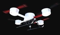
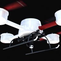
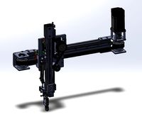
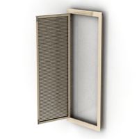
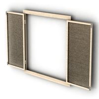
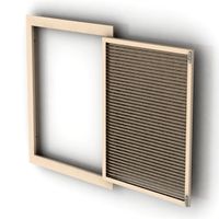
Mobius gimbal (2 axis) for 22mm motors and H frame by mcseven
by Thingiverse
Last crawled date: 3 years ago
Preface
This gimbal was based upon two other sources, of which unfortunately the source files are not available and both authors did not reply to my inquiries.
http://www.thingiverse.com/thing:216558
Here, the holder which turbi uploaded (other than shown in the pictures!), presses on the "power" button of the Mobius. Also, it's very difficult to print as the "roof" part has extremely thin walls. Overall, it looks very nice on his renderings, but was not designed for printing.
http://www.thingiverse.com/thing:332566
Here, the holder looks very nice, but is, unfortunately, is also not easy to print. When printing laid horizontally (not vertically as in the original images), some parts are in the air. Also, particularly without cooling fan, the small screw holes in the "tower" will be a mushy mess.
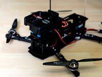
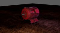
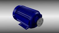
Turbi's design was created for 28mm motors, which are available through hobbyking. The lightest ones I could find were ~32g 2206-140KV, which is quite a lot. I wanted to have a gimbal with smaller and even lighter motors 1807-340KV (beware of their stiff cables though, see my photographs for suggested motor mounting position and cable guidance).
My overall weight is 154g with cam, controller board and cables, which seems to be extremely good compared to the metal gimbals you can buy off ebay or hobbyking.
Changes to original sources
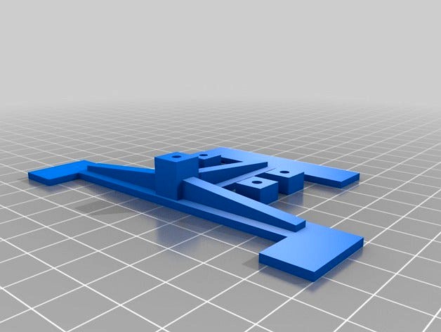
With the source STLs, it seems impossible to import the meshes with sketchup or Solidworks: both programs have "repair-on-open", which breakes a lot of faces. So I used OpenSCAD to augment the existing meshes and export a new complete STL. Worked fine.
The inner diameters of both motor holders were changed from 28mm to 22mm.
In order to balance the gimbal, I extended the Y axis holder arm a few mm.
The X shaped vibration dampener holder had too large holes. I reduced their diameter as well. Just measure the diameters you have and adapt if necessary.
In the cam holder I strengthened the 2 small flexible nipple arms that slide into the screw holes of the cam.
Also, I removed the curves from the mounting position of that holder and replaced it with a flat ugly box. Way easier to print and hopefully more stable.
Tools and Materials
Small cutter knife
M2.5 screws with nuts and washers (for motors)
maybe M2 screws with nuts and washers (the screw holes are very small)
PLA and ABS in your desired color. Natural / Transparent seems to be the strongest.
Four rubber vibration bumpers
Notes
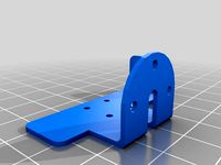
Use the mirrored cam holder in order to have the screw attachments at the respective bottoms (so they don't get in the way while rotation takes place).
In case you have a different frame, you'd need to design your own part of the top holder. Use a 8mm suare pillar to connect it to the top X shaped vibration dampener.
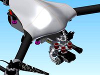
Also, see the pictures on how the StoRM32 is attached to the whole frame and how, in particular, the wires are guided. This setup may look strange but provides enough flexibility for all positions the camera can be moved into.
This gimbal was based upon two other sources, of which unfortunately the source files are not available and both authors did not reply to my inquiries.
http://www.thingiverse.com/thing:216558
Here, the holder which turbi uploaded (other than shown in the pictures!), presses on the "power" button of the Mobius. Also, it's very difficult to print as the "roof" part has extremely thin walls. Overall, it looks very nice on his renderings, but was not designed for printing.
http://www.thingiverse.com/thing:332566
Here, the holder looks very nice, but is, unfortunately, is also not easy to print. When printing laid horizontally (not vertically as in the original images), some parts are in the air. Also, particularly without cooling fan, the small screw holes in the "tower" will be a mushy mess.
Turbi's design was created for 28mm motors, which are available through hobbyking. The lightest ones I could find were ~32g 2206-140KV, which is quite a lot. I wanted to have a gimbal with smaller and even lighter motors 1807-340KV (beware of their stiff cables though, see my photographs for suggested motor mounting position and cable guidance).
My overall weight is 154g with cam, controller board and cables, which seems to be extremely good compared to the metal gimbals you can buy off ebay or hobbyking.
Changes to original sources
With the source STLs, it seems impossible to import the meshes with sketchup or Solidworks: both programs have "repair-on-open", which breakes a lot of faces. So I used OpenSCAD to augment the existing meshes and export a new complete STL. Worked fine.
The inner diameters of both motor holders were changed from 28mm to 22mm.
In order to balance the gimbal, I extended the Y axis holder arm a few mm.
The X shaped vibration dampener holder had too large holes. I reduced their diameter as well. Just measure the diameters you have and adapt if necessary.
In the cam holder I strengthened the 2 small flexible nipple arms that slide into the screw holes of the cam.
Also, I removed the curves from the mounting position of that holder and replaced it with a flat ugly box. Way easier to print and hopefully more stable.
Tools and Materials
Small cutter knife
M2.5 screws with nuts and washers (for motors)
maybe M2 screws with nuts and washers (the screw holes are very small)
PLA and ABS in your desired color. Natural / Transparent seems to be the strongest.
Four rubber vibration bumpers
Notes
Use the mirrored cam holder in order to have the screw attachments at the respective bottoms (so they don't get in the way while rotation takes place).
In case you have a different frame, you'd need to design your own part of the top holder. Use a 8mm suare pillar to connect it to the top X shaped vibration dampener.
Also, see the pictures on how the StoRM32 is attached to the whole frame and how, in particular, the wires are guided. This setup may look strange but provides enough flexibility for all positions the camera can be moved into.
Similar models
thingiverse
free

Modius Gimbal by turbi
...ectronic board "brushless gimbal".
the motors are 28mm external diameter.
http://www.youtube.com/watch?v=c6wqqfr00d8
thingiverse
free
Mobius Gimbal by fiendie
...will need:
brushless motors: http://goo.gl/lvkdxo
gimbal controller: http://goo.gl/en3oks
vibration dampers: http://goo.gl/eem41g
thingiverse
free

My Fly Dream Vibration Dampener by lacion
...com/hobbyking/store/__40614__vibration_damping_balls_100g_61_black_8_pcs_.html)
there are 4 m3 screw holes in the bottom plate.
thingiverse
free

Mobius Camera Holder for Open Brushless Gimbal by ewingate
...sible updates, maybe.
or, you know, print something even nicer by the original designer!http://www.thingiverse.com/thing:216558
thingiverse
free

Frame Brace with y-axis motor mount and screw holes (Anet A8) by JacobPed
...you can use to rest the motor on if you wish.
note that the dampener is represented in the skethup picture as the part in orange.
thingiverse
free
Gimbal for Mobius Action Cam with rotation Axis by Sternes
...ed version of the camera mount (lense of the camera is nearer to the roll axis)
added an angle mount, fits also for rctiger motor
grabcad
free

3 Axis Acrylic Mobius Brushless Gimbal
...ned to fit f450 quadcopter.
mobius and dumper model are from rafal niczyporuk (https://grabcad.com/library/mobius-cam-gimbal-1)
thingiverse
free

RunCam Swift dampened mount for S500 Quadcopter by bakedpotato
...can be directly attached to the front of the frame's pcb and help to reduce small vibrations induced by the motors and props.
thingiverse
free

Mobius Gimbal by Xcopter
...t mounted gimbal for the mobius.
i am in the works of printing one right now so the photos above are not actually the real thing.
thingiverse
free
Mobius Mini Gimbal by Dispectum
...
thingiverse
mobius mini gimbal for 1806 class brushless motors.
there is also the mould for carbon fiber camera holder version.
Mcseven
thingiverse
free

Kitchen Paper Roll Extender by mcseven
...ly is, and -moreover- really fits the holder.
long story short, this is my humble attempt at solving the issue. hope you like it!
thingiverse
free

Kettlebell Cookie Cutter by mcseven
...up's weld-tool doesn't really stitch, it creates tiny new lines where points do not match exactly... well,not bad anyway.
thingiverse
free

Customizable Scribing Tool by mcseven
...oduct.
anyhow, i decided to make the one i designed both customizable and public. hope it helps someone else in their endeavours.
thingiverse
free

Large Printable Filament Spool Holder by mcseven
...patible with "dasfilament"'s really large 2,3kg spools.
the smallest part (clip) isn't really necessary.
enjoy.
thingiverse
free

HMS Sh1tAway by mcseven
...o screw in from the front. these two prevent rotation, while the bottom one (with a washer) keeps the stick in the shovel.
enjoy.
thingiverse
free

Customizable everything box (waterproof) by mcseven
...*********************
// ** / cutouts
// **************************
there, you can remove the two already there and add your own.
thingiverse
free

Customizable Spool Holder Axis by mcseven
...iting (e.g. with sketchup's "round corners" script), set the respective parts lengths to zero in customizer.
enjoy.
thingiverse
free

Configurable Dishwasher Salt Funnel by mcseven
...pillars: how wide in mm should the pillars be?
length_of_pillars: how long (not height!) should the pillars be?
hope you like it!
thingiverse
free

Large TEVO Black Widow Spool Holder (Remix) by mcseven
..., so is the original stl. and, as in the original, you'd need two hammer nuts, two washers and two suitable m?-screws.
enjoy.
thingiverse
free

Cloud Rain Wall Flower Pot Thing (CLICK, REMIX) by mcseven
...017: made a cloud version with spacers for the coconut. thus, water goes really into the bowl.
thanks to 3dpvdb for a great item!
Mobius
design_connected
$11

Mobius
...mobius
designconnected
kristalia mobius coffee tables computer generated 3d model. designed by lucidi pevere.
turbosquid
free

Mobius
... available on turbo squid, the world's leading provider of digital 3d models for visualization, films, television, and games.
3d_export
$120

Mobius bracelet
...mobius bracelet
3dexport
mobius bracelet 3d render modelling animation
3ddd
$1

Mobius Table
...mobius table
3ddd
kristalia , кофейный
mobius coffee table by kristalia
design_connected
$25

Mobius C
...mobius c
designconnected
zenith mobius c computer generated 3d model. designed by schamburg, marc.
3d_export
$5
mobius bracelet
...mobius bracelet
3dexport
3d model of a mobius bracelet.<br>modeled in solidworks.<br>rendered in keyshot.
turbosquid
$19

red mobius
...bosquid
royalty free 3d model red mobius for download as max on turbosquid: 3d models for games, architecture, videos. (1353147)
turbosquid
free

Mobius Desk
...y free 3d model mobius desk for download as max, obj, and fbx on turbosquid: 3d models for games, architecture, videos. (1229898)
turbosquid
$2

Mobius ring
...e 3d model mobius ring for download as 3ds, max, obj, and fbx on turbosquid: 3d models for games, architecture, videos. (1195725)
turbosquid
free

Mobius strip
... available on turbo squid, the world's leading provider of digital 3d models for visualization, films, television, and games.
Gimbal
turbosquid
$1
Yuneec Save Stick for Gimbal
... available on turbo squid, the world's leading provider of digital 3d models for visualization, films, television, and games.
3d_export
$20

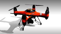
splashdrone gimbal camera
...nsions. all textures used have been included. thank you for purchasing this model!! click on my username to see more of my models
3d_export
$40
splashdrone 3 plus with gimbal camera
...nsions. all textures used have been included. thank you for purchasing this model!! click on my username to see more of my models
turbosquid
$88
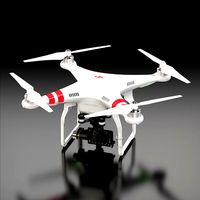
DJI Phantom 2 Quadcopter with gimbal for GoPro HERO4 or 3
... available on turbo squid, the world's leading provider of digital 3d models for visualization, films, television, and games.
3d_export
$5

concentrate box
...concentrate box 3dexport concealer box with handle and gimbal ...
cg_studio
$55
Drone Quadrocopter With Camera Rigged3d model
...fly wing propeller rc video camera sky dron spy gimbal gopro riged aircraft toy .obj .fbx .max .3ds -...
3d_ocean
$29
Drone Quadrocopter With Camera Rigged
...quadrocopter with camera rigged 3docean aircraft camera dron fly gimbal gopro propeller quadrocopter rc riged sky sport spy toy...
3ddd
free
Foucault's Iron Orb
...physicist léon foucault's gyroscope inspired our openwork globe. its double-gimbal frame is built of iron around a nucleus of...
thingiverse
free
Gimbal by tannermichael
...amera and gravity to self level. the gimbal uses .125" axles to pivot on. this gimbal was made using autodesk inventor 2015.
thingiverse
free

2020 Gimbal
...2020 gimbal
thingiverse
2020 gimbal
22Mm
turbosquid
$1

support mods 22mm for e-cig
... available on turbo squid, the world's leading provider of digital 3d models for visualization, films, television, and games.
3ddd
$1

JRM-0554
...производитель: johan-richard -http://www.johnrichard.com - модель: jrm-0554 размеры: w-610mm, d-1220mm, h-22mm ...
3d_export
$9

flower number 4
...121,643 edges: 364,995 facet: 243,330 tris: 243,330 x = 22mm y = 30 mm z = 2 mm need...
3d_export
$5

Cartouche-011
...carving on cnc machines length: 503mm width: 158mm height: 22mm ...
3d_export
$16
ring with stones
...ring with stones 3dexport current ring size is 22mm<br>ring rail size is 69.1<br>сentral stone is 6.5 mm<br>18 stones...
3d_export
$7

ring of blades
...in the archive.<br>ring diameter:<br>16mm 17mm 18mm 19mm 20mm 21mm 22mm 23mm<br>in the archive there are models of different quality:<br>high...
3d_export
$7

ring wild rocks
...wild rocks<br>ring diameter: 16mm 17mm 18mm 19mm 20mm 21mm 22mm 23mm need change write me: lilipop1122@mail.ru<br>there are 2 types...
3d_export
$5
puzzle cube
...to account for some sagging. the bridge length is 22mm cube size at default scale is...
3d_export
$7

knife
...igs<br>- stp<br>- stl<br>- knife: 20,232 vertices, 23,920 faces<br>- knife: (w)22mm (l)195mm (h)9mm<br>other models may be found in my...
3d_export
$19

cutlery set 3 pieces
...spoon: (w)42mm (l)180mm (h)11mm<br>- fork: (w)26mm (l)184mm (h)9mm<br>- knife: (w)22mm (l)195mm (h)9mm<br>other models may be found in my...
Axis
3ddd
$1
Мария Axis
...
3ddd
кухня , классическая , axis
модель кухни.
3d_export
$22
Axis robot 6-axis robotic arm
...ing parts drawings, standard parts purchased parts list, can be produced directly according to the drawings, welcome to download!
3ddd
free

Versatile Axis
...ddd
nexus , плитка
http://bvtileandstone.com/ceramic-porcelain/versatile-axis/
3d_export
$19
robot 2 axis
...robot 2 axis
3dexport
robot 2 axis
turbosquid
$40
Axis R5F
... available on turbo squid, the world's leading provider of digital 3d models for visualization, films, television, and games.
turbosquid
$40
Axis S5F
... available on turbo squid, the world's leading provider of digital 3d models for visualization, films, television, and games.
turbosquid
$30
Axis Athlon
... available on turbo squid, the world's leading provider of digital 3d models for visualization, films, television, and games.
turbosquid
$10

Linear Axis
... available on turbo squid, the world's leading provider of digital 3d models for visualization, films, television, and games.
3d_export
$15

drawing axis
...drawing axis
3dexport
simple rendering of the scene file
3ddd
$1
versatile axis ARC
...versatile axis arc
3ddd
versatile , плитка
versatile axis arc red dot design award
Motors
archibase_planet
free
Motor
...base planet
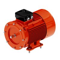
motor motor engine engine electric motor
motor wagner n250213 - 3d model (*.gsm+*.3ds) for interior 3d visualization.
archibase_planet
free
Motor
...motor
archibase planet
motor motor engine engine
motor n151112 - 3d model (*.gsm+*.3ds) for interior 3d visualization.
archibase_planet
free
Motor
...motor
archibase planet
motor motor engine engine
motor n150615 - 3d model (*.gsm+*.3ds+*.max) for interior 3d visualization.
turbosquid
$15
Motor
...otor
turbosquid
royalty free 3d model motor for download as on turbosquid: 3d models for games, architecture, videos. (1639404)
3d_ocean
$5
Electric motor
...electric motor
3docean
car electric engine industry motor phase train vehicle
an electric motor enjoy!
3d_ocean
$18
Electric Motor
...electric motor
3docean
electric motor engine machine mover parts
3d model electric motor for hoist crane
turbosquid
$29

Motor
... available on turbo squid, the world's leading provider of digital 3d models for visualization, films, television, and games.
turbosquid
$5
Motor
... available on turbo squid, the world's leading provider of digital 3d models for visualization, films, television, and games.
3d_export
$5
electric motor
...electric motor
3dexport
electric motor use for industrial purposes
3d_export
$5

servo motor
...tor
3dexport
it's a simple part of servo motor 0.75kw for used in machines assembly to show specified motor in own project.
Frame
archibase_planet
free
Frame
...frame
archibase planet
frame photo frame
frame n190813 - 3d model (*.gsm+*.3ds) for interior 3d visualization.
archibase_planet
free
Frame
...frame
archibase planet
frame photo frame
frame n071113 - 3d model (*.gsm+*.3ds) for interior 3d visualization.
3ddd
$1

Frame
...frame
3ddd
frame
3ddd
free
Frame
...frame
3ddd
frame
archibase_planet
free

Frame
...frame
archibase planet
frame mirror frame ornament
frame n260113 - 3d model (*.gsm+*.3ds) for interior 3d visualization.
archibase_planet
free

Frame
...frame
archibase planet
frame photo frame
frame photo n190813 - 3d model (*.gsm+*.3ds) for interior 3d visualization.
archibase_planet
free
Frame
...frame
archibase planet
frame window window frame
frame 1 - 3d model (*.gsm+*.3ds) for interior 3d visualization.
archibase_planet
free
Frame
...frame
archibase planet
frame window frame window
frame 3 - 3d model (*.gsm+*.3ds) for interior 3d visualization.
archibase_planet
free
Frame
...frame
archibase planet
frame wall frame decoration
frame 1 - 3d model (*.gsm+*.3ds) for interior 3d visualization.
archibase_planet
free
Frame
...frame
archibase planet
frame window window frame
frame 2 - 3d model (*.gsm+*.3ds) for interior 3d visualization.
2
design_connected
$11
No 2
...no 2
designconnected
sibast no 2 computer generated 3d model. designed by sibast, helge.
turbosquid
$6
Cliff Rock 2-2
...uid
royalty free 3d model cliff rock 2-2 for download as obj on turbosquid: 3d models for games, architecture, videos. (1619161)
turbosquid
$29

Book variation 2 2
...3d model book variation 2 2 for download as max, obj, and fbx on turbosquid: 3d models for games, architecture, videos. (1366868)
turbosquid
$22
Classic baluster (2) (2)
...assic baluster (2) (2) for download as max, obj, fbx, and stl on turbosquid: 3d models for games, architecture, videos. (1483789)
turbosquid
$99

Smilodon 2 Pose 2
... available on turbo squid, the world's leading provider of digital 3d models for visualization, films, television, and games.
turbosquid
$20

Barrel Barricade 2-2
... available on turbo squid, the world's leading provider of digital 3d models for visualization, films, television, and games.
turbosquid
$6

Wall Trophy (2) (2)
... available on turbo squid, the world's leading provider of digital 3d models for visualization, films, television, and games.
turbosquid
free
Tire label 2 of 2
... available on turbo squid, the world's leading provider of digital 3d models for visualization, films, television, and games.
3ddd
$1

Кровать, 2 тумбочки, 2 светильника
...кровать, 2 тумбочки, 2 светильника
3ddd
кровать, 2 тумбочки, 2 светильника
нормальное качество
формат 3ds max
без текстур
3ddd
free

Кровать, 2 тумбочки, 2 светильника
...кровать, 2 тумбочки, 2 светильника
3ddd
кровать, 2 тумбочки, 2 светильника
нормальное качество
формат 3ds max
без текстур