Thingiverse
Mk2B Bed Modification for Anet A8 by FredGenius
by Thingiverse
Last crawled date: 3 years ago
I upgraded my heated bed to a Mk2B heater pcb and borosilicate glass plate recently, thought I'd share the construction information and the printable parts.
Why upgrade? The aluminium plate is heavy, and because it heats up unevenly (hotter in the middle and cooler at the edges) it warps, making printing difficult, especially when you want a 0.1mm first layer.
The borosilicate glass makes an excellent build surface, and because it has a very low coefficient of thermal expansion it stays very flat.
Using larger, M4 screws to support the bed makes it more stable, and more durable.
So, by replacing the stock bed I've saved approximately 300 grams mass in the y axis, and have a very flat build surface. My print quality is excellent and I have no regrets.
You will need:
1x Mk2B heater pcb
1x 213mm x 200mm borosilicate glass plate
1x 100K NTC glass body thermistor
4x M4 x 35mm hex head bolts (or #8-32 x 1.5")
4x M4 (or #8-32) half nuts
4x binder clips
Kapton tape, and some strands of copper wire (I used strands from some 7/0.2mm equipment wire I had lying around, but almost any wire will do if you can solder it).
Tools:
An M4 or #8-32 tap to re-thread the holes in the H frame
A soldering iron and solder
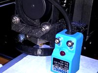
A digital multimeter
Method:
Choose the adjuster/locknut file, M4 or #8-32) for the hardware you have.
Start by printing the adjusters, lock wheels and caps - you need 8 wheels and 4 caps. Press the half nuts and bolt heads into the wheels.
Next, remove the old bed and de-solder or cut the wires. Also remove the screws and springs, you won't need them.
Take the thermistor and solder a strand of copper wire to each leg, long enough to reach the edge of the bed. Next, tape the thermistor to the underside of the pcb, there's a hole in the centre which is the perfect location. Tape the wires in place so they aren't touching and solder to the original thermistor cable (the two thin white wires).
Test the thermistor with a multimeter, it should read about 100K Ohms at room temperature, and fall slowly when you touch it.
Solder the heater wires to the pads provided. The Mk2B heater pcb is designed for either 12V or 24V supplies, so make sure you use the 12V option. Ignore the pads for the resistor and LEDs, they are not needed.
Secure the cables - I used two zip ties, one around the cables, the second looped through the hole in the PCB and through the first tie. This should provide adequate strain relief.
Next, use the M4 (or #8-32) tap to re-thread the holes at each corner of the H frame, no need to drill out the M3 holes first.
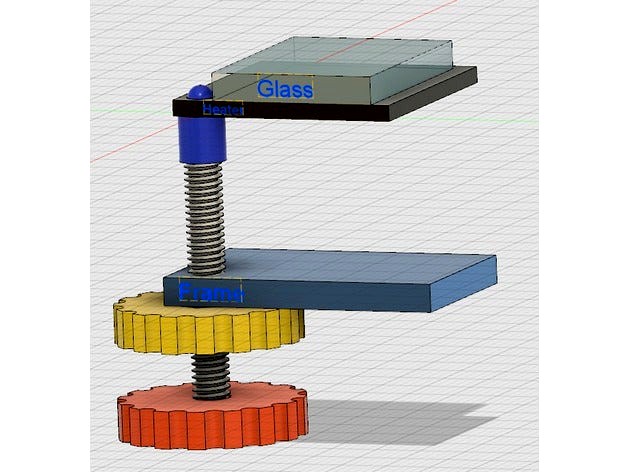
Screw the bolts with the adjuster and lock wheels in place through the H frame as per the diagram, and position the caps on top.
Rest the PCB on the caps, they should locate in the holes at each corner.
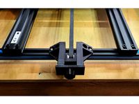
Position the glass on top of the PCB so the screw caps aren't obstructed and secure with the binder clips. I find that placing the clips at the sides rather than the front and back edges works best.
Connect your bed and thermistor to the main board, level your bed and you're good to go!
I've been using this setup since June 2017 without problems. The bed heats up really quickly and the glass is the best build surface I've tried. A smear of ABS Juice on the glass is all you need for good adhesion, and the print will come loose when the bed temperature drops below about 40C.
PS, be careful - if you run the nozzle into the bed you'll most likely break the glass.
Update! I've re-designed the caps, they are longer now, and have an M4 thread internally, making them a bit more stable. See below for print settings.
Update! I've added the adjuster-locknut and cap mesh for #8-32 bolts. :)
Update! Check out my differential corner adjusters, 0.3mm per turn! https://www.thingiverse.com/thing:3151276
Why upgrade? The aluminium plate is heavy, and because it heats up unevenly (hotter in the middle and cooler at the edges) it warps, making printing difficult, especially when you want a 0.1mm first layer.
The borosilicate glass makes an excellent build surface, and because it has a very low coefficient of thermal expansion it stays very flat.
Using larger, M4 screws to support the bed makes it more stable, and more durable.
So, by replacing the stock bed I've saved approximately 300 grams mass in the y axis, and have a very flat build surface. My print quality is excellent and I have no regrets.
You will need:
1x Mk2B heater pcb
1x 213mm x 200mm borosilicate glass plate
1x 100K NTC glass body thermistor
4x M4 x 35mm hex head bolts (or #8-32 x 1.5")
4x M4 (or #8-32) half nuts
4x binder clips
Kapton tape, and some strands of copper wire (I used strands from some 7/0.2mm equipment wire I had lying around, but almost any wire will do if you can solder it).
Tools:
An M4 or #8-32 tap to re-thread the holes in the H frame
A soldering iron and solder
A digital multimeter
Method:
Choose the adjuster/locknut file, M4 or #8-32) for the hardware you have.
Start by printing the adjusters, lock wheels and caps - you need 8 wheels and 4 caps. Press the half nuts and bolt heads into the wheels.
Next, remove the old bed and de-solder or cut the wires. Also remove the screws and springs, you won't need them.
Take the thermistor and solder a strand of copper wire to each leg, long enough to reach the edge of the bed. Next, tape the thermistor to the underside of the pcb, there's a hole in the centre which is the perfect location. Tape the wires in place so they aren't touching and solder to the original thermistor cable (the two thin white wires).
Test the thermistor with a multimeter, it should read about 100K Ohms at room temperature, and fall slowly when you touch it.
Solder the heater wires to the pads provided. The Mk2B heater pcb is designed for either 12V or 24V supplies, so make sure you use the 12V option. Ignore the pads for the resistor and LEDs, they are not needed.
Secure the cables - I used two zip ties, one around the cables, the second looped through the hole in the PCB and through the first tie. This should provide adequate strain relief.
Next, use the M4 (or #8-32) tap to re-thread the holes at each corner of the H frame, no need to drill out the M3 holes first.
Screw the bolts with the adjuster and lock wheels in place through the H frame as per the diagram, and position the caps on top.
Rest the PCB on the caps, they should locate in the holes at each corner.
Position the glass on top of the PCB so the screw caps aren't obstructed and secure with the binder clips. I find that placing the clips at the sides rather than the front and back edges works best.
Connect your bed and thermistor to the main board, level your bed and you're good to go!
I've been using this setup since June 2017 without problems. The bed heats up really quickly and the glass is the best build surface I've tried. A smear of ABS Juice on the glass is all you need for good adhesion, and the print will come loose when the bed temperature drops below about 40C.
PS, be careful - if you run the nozzle into the bed you'll most likely break the glass.
Update! I've re-designed the caps, they are longer now, and have an M4 thread internally, making them a bit more stable. See below for print settings.
Update! I've added the adjuster-locknut and cap mesh for #8-32 bolts. :)
Update! Check out my differential corner adjusters, 0.3mm per turn! https://www.thingiverse.com/thing:3151276
Similar models
thingiverse
free

Glass Bed Corner Supports by GORILLA_PARTS
...hese are corner supports for adapting common 213mm x 200mm borosilicate glass plates to a 214mm x 214mm prusa mk2b pcb heat bed.
thingiverse
free

YAHexagonalHeatedBedHolder - "mind the solder joints" version by nmaggioni
...x slightly larger washers to avoid the bolts sliding out of aluminium beams.
see the post-printing section for more instructions.
thingiverse
free

Ultimaker 2 clone base plate - MK2b ready by S3bape
...ter since i prefer m3 nylock nuts for heated bed leveling over um2 thumb screws.
i recommend to laser cut it of 4mm pa6 aluminum.
thingiverse
free

Ender 3 Pro Glass Bed Clips by ItchyJuffoWup
...arp over time. eventually, i would recommend printing them with either petg or abs to withstand the constant heating and cooling.
thingiverse
free

Glass Clip For 3mm Glass & MK2B Heat bed by mr_paiko
...glass clip for 3mm glass & mk2b heat bed by mr_paiko
thingiverse
a rigid clip for 3mm glass on mk2b pcb heat_bed
thingiverse
free

IC Pin Straightener (8-32 Thread) by dcdalrymple
...
2x: #8-32 x 1.25" socket head cap screw (1.75" for wide version)
4x: compression spring, 3/8" long x 0.3" od
thingiverse
free

Ender 3 Ultimate Spool Holder
...t combos (for attaching to frame)
spoolholder part has guide hole that can be drilled out if m3 bolt does not have leading point.
thingiverse
free

GLASS BED HOLDER 220 mm GLASS by angelriv
... allen bolt
you also need 3 m4 x 10 allen bolts and 3 m4 square nuts
you can also use longer bolts with a couple of plain washers
thingiverse
free

Shelf Mounted Spool Holder
...
1x m12 hexagonal nut
2x m8 bolt
2x m8 hexagonal nut
1x m4 screw
1x m4 nyloc nut
6x m4 torx wood screws
1x 25x600mm aluminum tube
thingiverse
free
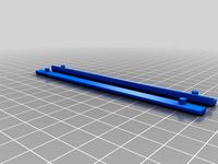
CR-10 S5 Y Axis Belt Tensioner - Improved Lower Profile by terrylamprecht
...nch the belt wheel/bearing. i have included both the .stp files and the stls. please feel free to make additional improvements.
Fredgenius
thingiverse
free

Vape Juice Filler Nozzle by FredGenius
... filler nozzle by fredgenius
thingiverse
vape juice filler nozzle, screws on to a standard bottle, better for filling your tank.
thingiverse
free
Micro-SD Card Display Stand by FredGenius
...micro-sd card display stand by fredgenius
thingiverse
a display stand for your micro-sd card collection. enjoy!
thingiverse
free
Vape Grips by FredGenius
...ce to hold, and helps to keep the pen from falling over. two sizes, both for 14mm diameter pens, 72mm and 48mm tall respectively.
thingiverse
free

Palette Knife by FredGenius
... to 0.1mm
if you want a stiffer blade, scale the z axis in your slicer program.
please leave a comment if you find this useful...
thingiverse
free

Salt Cellar by FredGenius
...low a few grains to trickle out. perfect for my breakfast boiled eggs, perfect if you're trying to reduce your sodium intake.
thingiverse
free
QCTP DTI Holder by FredGenius
...r the adjuster screw is threaded, m5x0.8
the adjuster screw is a m5x30 set screw, the brass adjuster nut you can make yourself...
thingiverse
free
Filament Plunger by FredGenius
... any crud will be stuck to the rod, and can be removed easily.
if anyone can suggest a better name for this tool, please tell me!
thingiverse
free

Arduino Uno Base Plate by FredGenius
...mply push-fits in to place, can easily be removed when required, but a little hot-melt glue will make it a little more permanent.
thingiverse
free
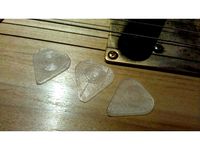
Scalable Guitar Pick by FredGenius
...esses and see what works best for you.
i printed mine with pla but no reason why abs won't work if you allow for shrinkage...
thingiverse
free
CNC Digitizing Probe by FredGenius
...an be bought here: https://www.ebay.co.uk/itm/322792083221 - although might be a while before you find uses for the other 99 lol!
Mk2B
thingiverse
free

3DR MK2/MK2B heated bed adapter by ghaffar47
...bed adapter by ghaffar47
thingiverse
this is an adapter for 3dr with extension for mounting mk2 / mk2b heated bed
happy printing
thingiverse
free
Glass Clip For 3mm Glass & MK2B Heat bed by mr_paiko
...glass clip for 3mm glass & mk2b heat bed by mr_paiko
thingiverse
a rigid clip for 3mm glass on mk2b pcb heat_bed
thingiverse
free

MK2B Drill/tap template by ZUK3D
...ut from the center hole 104.5mm to each side to mark center for drill. then use a square and mark 209mm from top holes to bottom.
thingiverse
free
MK2B glass holder/stabiliser by Wydryszek
...wo minutes to just help with print quality....and yes quality is now better :)
i'm still using three clips to hold the glass.
thingiverse
free

MK2B Heated Bed Support for Kossel 2020 by engineer119
...2 units
heatedbed-support2 ... 2 units
cap screw m3x25mm + sw m3 + washer m3 + nut m3 + spring 4mmx17mm + nylon nut m3 ... 4 sets
thingiverse
free
Ultimaker 2 clone base plate - MK2b ready by S3bape
...ter since i prefer m3 nylock nuts for heated bed leveling over um2 thumb screws.
i recommend to laser cut it of 4mm pa6 aluminum.
thingiverse
free

MakerBot Replicator 2 MK2B Heat-plate Adaptor by DMEngineering
...eces so that it can be printed on a typical sized 3d printer joined with two dowels. a soft mallet can be used to tap into place.
thingiverse
free

MK2B LED Light Protector by lboucher
...ll down a bit on the heatbed to help level it if, if needed.
i have a piece of corkboard under my heatbed, so adjust as needed.
thingiverse
free

QUBD Twoup MK2B heated bed supports by Jakontheroad
...ork with m3 screws and nuts to attach the bed to them.
i used 6 x 1/2 metal screws to attach the support to the bed (see photos)
thingiverse
free
mk2b heated bed model for s3d by rockpaperlizardspock
...de>
note: this is not a technical drawing, it is just for aesthetic purposes in simplify3d to easily visualise the build area.
A8
turbosquid
$47

Car A8
...
turbosquid
royalty free 3d model car a8 for download as max on turbosquid: 3d models for games, architecture, videos. (1196060)
turbosquid
$50

Audi A8
...yalty free 3d model audi a8 for download as 3dm, obj, and fbx on turbosquid: 3d models for games, architecture, videos. (1580187)
turbosquid
$15

Audi A8
...lty free 3d model audi a8 for download as obj, fbx, and blend on turbosquid: 3d models for games, architecture, videos. (1387519)
turbosquid
$500

Audi A8
... available on turbo squid, the world's leading provider of digital 3d models for visualization, films, television, and games.
3d_export
$5

Audi A8 3D Model
...audi a8 3d model
3dexport
audi a8 cars car
audi a8 3d model ma 20351 3dexport
3d_export
$5

Audi A8 3D Model
...audi a8 3d model
3dexport
3d model of audi a8
audi a8 3d model badyaka 12136 3dexport
3d_ocean
$89

Audi A8 2010
...usiness car car class class f f german german luxury luxury s s s8 s8 sedan sedan vehicle vehicle
new audi a8 2010 detaled model.
turbosquid
$39

A8 2018
...a8 2018 for download as 3ds, obj, wrl, c4d, fbx, dae, and stl on turbosquid: 3d models for games, architecture, videos. (1345349)
turbosquid
free

audi a8 l
...rbosquid
royalty free 3d model audi a8 l for download as obj on turbosquid: 3d models for games, architecture, videos. (1663016)
3d_ocean
$45

Audi A8 restyled
...our door vehicle was created in blender3d 2.62.realistic renderings were created with yafaray 0.1.2 realistic plugin.rendering...
Anet
thingiverse
free

Anet by derbodesign
...anet by derbodesign
thingiverse
logo anet
thingiverse
free
Anet e10 , Anet v1.0 by jonathan_943D
...anet e10 , anet v1.0 by jonathan_943d
thingiverse
soporte de ventilador de 80mm, para controladora anet v1.0
thingiverse
free
Anet A8 Anet AM8 Y belt holder
...anet a8 anet am8 y belt holder
thingiverse
anet a8 anet am8 y belt holder
thingiverse
free
Anet A8 Probe Bracket for anet sensor by chelrix
...anet a8 probe bracket for anet sensor by chelrix
thingiverse
anet a8 probe bracket for anet official sensor and marlin firmware
thingiverse
free
Anet logo by JUST3D_PRNTNG
...anet logo by just3d_prntng
thingiverse
anet logo
thingiverse
free
Fan nozzle for Anet A8 with original Anet levelsensor by peteruhlmann
...et levelsensor by peteruhlmann
thingiverse
here is an improved fan nozzle for the anet a8 with original level sensor from anet.
thingiverse
free
Anet Et4 Box
...anet et4 box
thingiverse
tool box for anet et4
thingiverse
free
Anet Logo by Superflex_Plastic_Fantastic
...anet logo by superflex_plastic_fantastic
thingiverse
anet logo to incorporate into designs.
thingiverse
free
Box for Anet ET4
...box for anet et4
thingiverse
this is a simple box for tool of anet et4
thingiverse
free

Anet V1.0 Board Kühlung (80mm Lüfter) / Anet A8 by MadCre8
...anet v1.0 board kühlung (80mm lüfter) / anet a8 by madcre8
thingiverse
anet v1.0 board kühlung (80mm lüfter) / anet a8
Modification
turbosquid
$12
AKMS (AK47 modification)
... available on turbo squid, the world's leading provider of digital 3d models for visualization, films, television, and games.
turbosquid
$79
BusTransForm - Modif Bus Thailand
...d model bustransform - modif bus thailand for download as obj on turbosquid: 3d models for games, architecture, videos. (1383303)
3d_export
$25

mitsubishi evo 9 modification
...mitsubishi evo 9 modification
3dexport
evo 9 has been modified with a nice and elegant look.
3d_ocean
$25

Dart Vader (modificated helm)
...niforms, as well as anatomical model of the character itself. the model is divided into groups for further editing. primarily ...
turbosquid
$15

FN SCAR-H modification low-poly game ready
...fication low-poly game ready for download as ma, obj, and fbx on turbosquid: 3d models for games, architecture, videos. (1386384)
3d_export
$5

sphere light
...sphere light
3dexport
the socket and light are modifables
3d_export
$5

Fabulous chest
...chest 3dexport fabulous chest for your game or further modification ...
3d_export
free

cold coffee
...cold coffee 3dexport cold coffee can. any required modification will be done at...
3d_ocean
$12

Cartoon Dump or Sand Truck
...already rig low poly modifier still in stack for modification unwrap uvw for material and colour...
3d_ocean
$12

Cartoon Cement Mixer Truck
...already rig low poly modifier still in stack for modification unwrap uvw for material and colour...
Bed
3ddd
$1

bed
...bed
3ddd
bed , постельное белье
bed
3ddd
$1

bed
...bed
3ddd
bed , постельное белье
bed
3ddd
$1
bed
...bed
3ddd
bed , постельное белье
bed
3ddd
$1

bed
...bed
3ddd
bed , постельное белье
bed
3ddd
$1
bed
...bed
3ddd
bed , постельное белье
bed
3ddd
$1

bed
...bed
3ddd
bed , постельное белье
bed
3ddd
free
bed
...bed
3ddd
bed , постельное белье
bed
3ddd
free

bed
...bed
3ddd
bed , постельное белье
bed
3ddd
$1
Bed
...bed
3ddd
bed , постельное белье , постель
bed
3d_export
$7

bed adairs bed
...rs bed
3dexport
bed adairs bed in modern style. if you want a smoother surface, please turn on turbosmooth in the modifier list.