Thingiverse
Mini Tailsitter VTOL by Lob0426
by Thingiverse
Last crawled date: 3 years ago
this is a work in progress
This is a non-scale drawing of a design by a Flite Test Forum member slembcke. He was making a very small VTOL tail sitter plane (fixed wing)
https://forum.flitetest.com/index.php?threads/mini-tail-sitter-vtol-wing.36637/#post-369841
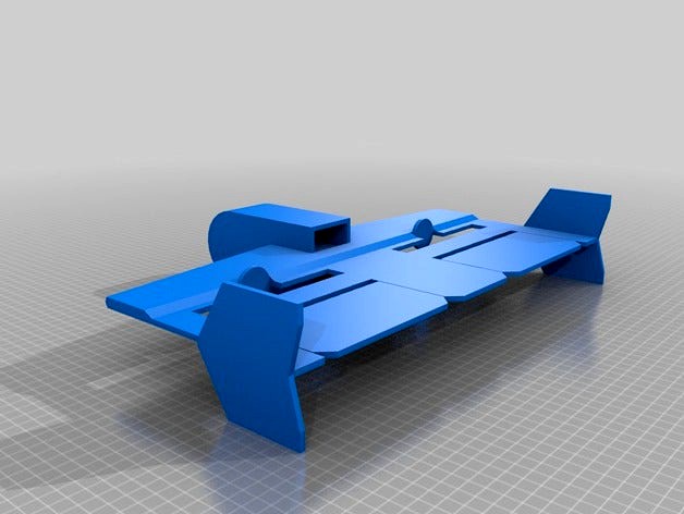
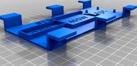
I made a few changes as it is not to scale anyway. It is a KF2 step Airfoil design (Kline-Fogelman). It is made with Dollar Tree Foam Board. Also known as Adams Readi-board. This drawing is 400mm X 280mm tall, when standing on its tail. The rudders are fixed and rudder is by differential motor control, while in plane mode. In VTOL mode the Yaw axis is by Elevons.
He originally powered it with 1304 brushless motors in front of the wings. He eventually moved to 1806 motors midline in the wing. He used a custom programmed Seriously DoDo controller from RMRC.
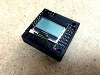
I plan on following up his work. Not being a programmer I will be using a KK2.1.5 Mini Flight Controller which is 36X36mm form factor. The stock firmware has been replaced with OpenAero2VTOL firmware. I am also planning on using 1806 2280K motors with 5X4 propeller's.
He was using a very small battery in his and had relatively short flight times. I think the design needs to be sized up some to get better flight times with heavier batteries. But I would like to start where he is right now. I hope he will return to the project. He was making good progress. This is my first drawing that has so much work into it. Still some to learn about SketchUp (2016). I first tried Fusion 360 but was getting nowhere with it. I will have to try it again.
Again this work was not began by me so make sure you attribute the work fairly if you try it out!
Ver 2 files; lengthened the KF step to add strength, fixed some mismatches. This thing will need some sort of spar if you plan to build it. the best place would be under the KF Step and above the wing sheet. I would put a groove in both the step and the wing sheet and hot glue the spar inside them both.
I am considering redoing this for 3D printing.
NOTES;
Version 3 has all the changes listed below. It will still accept a battery over 100mm long inside the fuselage. Additional changes. Cleaned up all hidden geometry. Internal fuselage front pod properly formed now. More than enough room for a FPV Camera and Transmitter. Limited to 5" (127mm) props. This thing is about ready for a build out of Readi-Board. Worried the pod may be to far out front now. have to build it to find out!
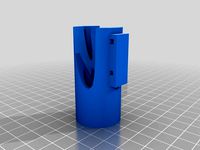
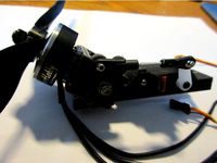
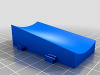
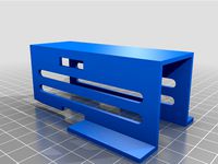
The upper compartment of the fuselage pod is meant to house the Flight Controller and the Receiver. The Lower compartment is for the Flight Battery. The Battery compartment is really large. I think the battery for this is going to be a 4S 1P 1300ma. The Battery compartment can hold 2 of these batteries side by side. And it is 100mm deep where the Batteries are only around 69mm to 75mm in length. In other words the Fuselage pod is on the large side. It needs to be reduced some to save weight. A little more height in the electronics bay would be nice as it is only 16mm tall. You could use a 2200ma in the battery bay. But the amount of wing on this will not carry the weight
I think you can use hard wood dowels from the local hardware store for spars. I would use two almost full width. As stated above I would score the KF step and the Wing sheet and imbed the spars between them.
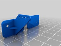
The motor mounts will most likely be mid chord. This means cutting slots that are about 5.25" (133.33mm) on each side of the centerline. This may cause strength issues in the trailing edge.
All of the tail surfaces are touching the ground. This is a no no in a VTOL aircraft. At the very least the control surfaces have to be clear the ground so they can move freely. Plus there needs to be some pass through space except for the pieces that are keeping the plane vertical.
Recommend 5" X 4.5" Bullnose Propeller's.
Foot Note; for those of you that wonder why these things get done in stages and versions. At this point I have probably 10 hours into computer time drawing this up. There is probably another couple of hours into research like battery sizes and motor weights. Then getting any changes into the next version. And some more research for propeller sizes and pitch for maximum thrust. Not to mention probably an hour or so posting all of this into Thingiverse with my slow typing! LOL!
Build comments: Most major parts now cut out of Black colored Readi-board. Need to find my compass to draw half circles on pod sides. Forgot how easy the Flitetest Speed Build kits are. It has been a couple years, or so, since I scratch built an Armin/Experimental Airlines style plane. Cutting this out will remind you. LOL! I would say beginner/intermediate level build. The KF2 style wing makes it easier.
Still need to cut the motor/prop holes in main wing. A Flite Test Power Pack A has everything except the flight controller. I am using the KK 2.1.5 Mini. It is 36 X 36mm. These flight controllers have been hard to come by lately. The pod is not wide enough to fit the full size board 52 X 52mm. It may fit up in the front of the fuselage pod on one side or another. I will check this out when I get further along. The pod may get changed to allow the KK 2.1.5 and the KK 2.1HC. The hard case version is pretty heavy for such a small format. More expensive FC's like the Pixhawk mini should fit easily.
After I get this test flown I will make some plans, if it goes well. Most of this is going to be "butt" glued in place. There are a few places where adding glue tabs would improve strength and make it more accurate to assemble. I also think the pod will need to be shortened for better balance.
So far it is going well. Stay tuned, I know I am slow bare with me!
5/31/18:
Airframe mostly assembled, no electronics as yet. Some adjustments made in scratch build. Pod widened to 60mm. This should allow a full size KK board. My scratch building skills are not back up to par as yet, struggling, but it is getting done. Not pretty but pretty solid so far. Unintended design consequence seen. LOL! When set horizontal the pod and vertical stabs align almost level. I need to add 6 to 8mm to the underside of the pod or remove from the bottom of the stabilizers. I will make sure that makes it into the final drawings.
This is a non-scale drawing of a design by a Flite Test Forum member slembcke. He was making a very small VTOL tail sitter plane (fixed wing)
https://forum.flitetest.com/index.php?threads/mini-tail-sitter-vtol-wing.36637/#post-369841
I made a few changes as it is not to scale anyway. It is a KF2 step Airfoil design (Kline-Fogelman). It is made with Dollar Tree Foam Board. Also known as Adams Readi-board. This drawing is 400mm X 280mm tall, when standing on its tail. The rudders are fixed and rudder is by differential motor control, while in plane mode. In VTOL mode the Yaw axis is by Elevons.
He originally powered it with 1304 brushless motors in front of the wings. He eventually moved to 1806 motors midline in the wing. He used a custom programmed Seriously DoDo controller from RMRC.
I plan on following up his work. Not being a programmer I will be using a KK2.1.5 Mini Flight Controller which is 36X36mm form factor. The stock firmware has been replaced with OpenAero2VTOL firmware. I am also planning on using 1806 2280K motors with 5X4 propeller's.
He was using a very small battery in his and had relatively short flight times. I think the design needs to be sized up some to get better flight times with heavier batteries. But I would like to start where he is right now. I hope he will return to the project. He was making good progress. This is my first drawing that has so much work into it. Still some to learn about SketchUp (2016). I first tried Fusion 360 but was getting nowhere with it. I will have to try it again.
Again this work was not began by me so make sure you attribute the work fairly if you try it out!
Ver 2 files; lengthened the KF step to add strength, fixed some mismatches. This thing will need some sort of spar if you plan to build it. the best place would be under the KF Step and above the wing sheet. I would put a groove in both the step and the wing sheet and hot glue the spar inside them both.
I am considering redoing this for 3D printing.
NOTES;
Version 3 has all the changes listed below. It will still accept a battery over 100mm long inside the fuselage. Additional changes. Cleaned up all hidden geometry. Internal fuselage front pod properly formed now. More than enough room for a FPV Camera and Transmitter. Limited to 5" (127mm) props. This thing is about ready for a build out of Readi-Board. Worried the pod may be to far out front now. have to build it to find out!
The upper compartment of the fuselage pod is meant to house the Flight Controller and the Receiver. The Lower compartment is for the Flight Battery. The Battery compartment is really large. I think the battery for this is going to be a 4S 1P 1300ma. The Battery compartment can hold 2 of these batteries side by side. And it is 100mm deep where the Batteries are only around 69mm to 75mm in length. In other words the Fuselage pod is on the large side. It needs to be reduced some to save weight. A little more height in the electronics bay would be nice as it is only 16mm tall. You could use a 2200ma in the battery bay. But the amount of wing on this will not carry the weight
I think you can use hard wood dowels from the local hardware store for spars. I would use two almost full width. As stated above I would score the KF step and the Wing sheet and imbed the spars between them.
The motor mounts will most likely be mid chord. This means cutting slots that are about 5.25" (133.33mm) on each side of the centerline. This may cause strength issues in the trailing edge.
All of the tail surfaces are touching the ground. This is a no no in a VTOL aircraft. At the very least the control surfaces have to be clear the ground so they can move freely. Plus there needs to be some pass through space except for the pieces that are keeping the plane vertical.
Recommend 5" X 4.5" Bullnose Propeller's.
Foot Note; for those of you that wonder why these things get done in stages and versions. At this point I have probably 10 hours into computer time drawing this up. There is probably another couple of hours into research like battery sizes and motor weights. Then getting any changes into the next version. And some more research for propeller sizes and pitch for maximum thrust. Not to mention probably an hour or so posting all of this into Thingiverse with my slow typing! LOL!
Build comments: Most major parts now cut out of Black colored Readi-board. Need to find my compass to draw half circles on pod sides. Forgot how easy the Flitetest Speed Build kits are. It has been a couple years, or so, since I scratch built an Armin/Experimental Airlines style plane. Cutting this out will remind you. LOL! I would say beginner/intermediate level build. The KF2 style wing makes it easier.
Still need to cut the motor/prop holes in main wing. A Flite Test Power Pack A has everything except the flight controller. I am using the KK 2.1.5 Mini. It is 36 X 36mm. These flight controllers have been hard to come by lately. The pod is not wide enough to fit the full size board 52 X 52mm. It may fit up in the front of the fuselage pod on one side or another. I will check this out when I get further along. The pod may get changed to allow the KK 2.1.5 and the KK 2.1HC. The hard case version is pretty heavy for such a small format. More expensive FC's like the Pixhawk mini should fit easily.
After I get this test flown I will make some plans, if it goes well. Most of this is going to be "butt" glued in place. There are a few places where adding glue tabs would improve strength and make it more accurate to assemble. I also think the pod will need to be shortened for better balance.
So far it is going well. Stay tuned, I know I am slow bare with me!
5/31/18:
Airframe mostly assembled, no electronics as yet. Some adjustments made in scratch build. Pod widened to 60mm. This should allow a full size KK board. My scratch building skills are not back up to par as yet, struggling, but it is getting done. Not pretty but pretty solid so far. Unintended design consequence seen. LOL! When set horizontal the pod and vertical stabs align almost level. I need to add 6 to 8mm to the underside of the pod or remove from the bottom of the stabilizers. I will make sure that makes it into the final drawings.
Similar models
thingiverse
free

Wing spar support for Talon Pro mini talon by epquilloy
...ment from the wing spar by having more surface are in contact. apply glue to mount to the fuselage.
note: print 2 pieces of this.
thingiverse
free
Flying Wing Motor Pods for VTOL by nfluester
...rse
1st draft wing pods designed for a tek sumo and wingwing z84 either if you want to make a twin wing or play around with vtol
thingiverse
free
Mini Skyhunter VTOL by kerrycorcoran
...y trays were inspired from grahame addicott designs.
the boom mounts are for the stock boom tubes and some additional 10mm tubes.
thingiverse
free

FT Mini Arrow Power Pod (Fuselage Modified for 1500mah Battery) by RotorGator
... does bring the cog back, but the 1500mah battery compensates for it.
the pod fits into a fuselage cavity measuring 35mm x 28mm.
grabcad
free

Eagle E-4 VTOL Cargo Drone
...lid entry in this challenge.
now i´m working in a improved version of this drone because i think that is an interesting concept.
thingiverse
free
KK Mini Case by mitchellcook5
...hingiverse
-flight controller case for the new kk mini flight controller, with button extensions!
-please read instructions!!!
grabcad
free

Wing Ribs and Spars
...eabouts depending on wing sweep) to the fuselage. the spar carries flight loads and the weight of the wings whilst on the ground.
thingiverse
free

Esprite VTOL Tail-sitter
...s
propellers: max. 16in
battery: 3 to 6s lipo
cg line is ~240mm from the nose.
initial flight test: https://youtu.be/29rkdaucqeq
grabcad
free

Quadcopter SM450
...e
simonk 20a escs
sunnysky x2212 980 kv motors
kk 2.0 flight control board
turnigy nanotech 3s 3300 mah battery
10x4.5 propellars
thingiverse
free

Nano Talon - wing spar conversion by CrashAndBash
...to hacksaw through some plastic.
5/ glue wing spar holder in place. i used uhu por.
6/ trim spar to the right length
happy flying
Tailsitter
thingiverse
free
Tilt Motor Mount by ATXHELI
...are aligned perfectly for forward flight. the other for tailsitter applications which use +/-45 deg tilts from vertical. ball...
grabcad
free

UAV Tailsitter
...uav tailsitter
grabcad
a tailsitter capable of vtol with 2 propellers and 2 ailerons
cg_trader
$45

Focke Wulf Triebflugel
...central germany. it was a vertical take-off and landing tailsitter interceptor design for local defense of important factories or...
3dwarehouse
free
Heinkel Lerche II
...#defense #german #germany #he #heinkel #ii #lerche #point #reich #tailsitter ...
3dwarehouse
free

Triebflugel
...a alemanha . foi um vertical take-off and landing tailsitter interceptor de design para a defesa de locais importantes...
Lob0426
thingiverse
free
Eflite Apprentice control Horns by Lob0426
...e apprentice control horns
the same ones are used on rudder, elevator and the ailerons. the only difference is the screw lengths.
thingiverse
free
Parkzone Radian Pro Camera Mount by Lob0426
...s is a radian pro camera mount. it is hot glued behind the canopy. your camera is held on by rubber bands.
includes sketchup file
thingiverse
free

Video Transmitter mount for Indy250 plus. by Lob0426
...ingiverse
mounts vtx to back of indy250 plus frame. uses 3m double sided 20lb tape. mounts tx vertical.
sketchup file included
thingiverse
free

Tarot200A quadcopter skid risers by Lob0426
...op of the frame. no more worry about the props hitting the battery. allows use of larger batteries.
the sketchup file is included
thingiverse
free

Benbox DIY Laser fan mount by Lob0426
...the top of the laser/fan and then down. then it is bent out to put air around the laser path to clear the smoke.
work in progress
thingiverse
free

AXN Floater Jet (CloudsFly from Hobby King) Canopy Clip by Lob0426
...the canopy to slip in between upper and lower plates. version 2 tight fit.
insert into foam where original was and epoxy in place
thingiverse
free

Leading Edge clip for Foam board repair and builds by Lob0426
...dynamics.
i recommend you hot glue this on for the best strength. it will stay on without glue.
let me know how it works for you!
thingiverse
free
AXN Battery box by Lob0426
... and caused it to split on impact, also the battery pushed against the top of the body. this was corrected in the newer version.
thingiverse
free

Duet 8.5 motor adapter by Lob0426
...st successful. almost hovers at 50% power.
faster with more turn authority. battery must be all the way back as far as it can go.
thingiverse
free

Flite Test Mini Scout elevator repair clip by Lob0426
...s readi-board aircraft. keep a few in your field box for instant repairs of tears can also be used to repair leading edge damage.
Vtol
turbosquid
$2

Vtol
... available on turbo squid, the world's leading provider of digital 3d models for visualization, films, television, and games.
turbosquid
free

Vtol
... available on turbo squid, the world's leading provider of digital 3d models for visualization, films, television, and games.
turbosquid
$25

vtol plane private
...oyalty free 3d model vtol plane private for download as blend on turbosquid: 3d models for games, architecture, videos. (1253756)
turbosquid
$8
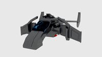
CRT Vtol X
...odel crt vtol x for download as 3ds, obj, fbx, blend, and dae on turbosquid: 3d models for games, architecture, videos. (1280946)
turbosquid
free

Stalker VTOL Sketchup
... available on turbo squid, the world's leading provider of digital 3d models for visualization, films, television, and games.
turbosquid
$10

Flying combat machine VTOL
... available on turbo squid, the world's leading provider of digital 3d models for visualization, films, television, and games.
turbosquid
$129

Camouflage VTOL (Landed & Flying)
... available on turbo squid, the world's leading provider of digital 3d models for visualization, films, television, and games.
turbosquid
free

VTOL V48 - Night Eagle
...eagle for download as 3ds, max, obj, fbx, blend, dae, and stl on turbosquid: 3d models for games, architecture, videos. (1251654)
turbosquid
free

Jet VTOL Hydro Genade Sub Rocket
... available on turbo squid, the world's leading provider of digital 3d models for visualization, films, television, and games.
3d_export
$50

vtol v-48 - night eagle
...ve (1)<br>(does not have) if there are objects with transparency such as leaves and branches there will be the specular map
Mini
turbosquid
$10
Mini Mini Luceplan
...
royalty free 3d model mini mini luceplan for download as max on turbosquid: 3d models for games, architecture, videos. (1227359)
3d_ocean
$39

Mini Cooper
...mini cooper
3docean
cabrioler cooper mini
mini cooper cabrioler
3d_export
$30

Mini lathe
...mini lathe
3dexport
mini lathe
3d_export
$5

mini mouse
...mini mouse
3dexport
mini mouse
3d_export
$5

mini house
...mini house
3dexport
mini house
3d_export
free

Mini Mecha
...mini mecha
3dexport
concept of mini mecha
3d_ocean
$20
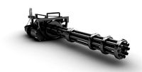
Mini Gun
...mini gun
3docean
gatling gun gun machine gun mini gun weapon
model of a mini gatling gun.
3ddd
free

Herve mini
... кофейный , herve
http://www.mobiliavenanti.it/ru/products/hervè-mini
3d_export
$5
mini wall
...mini wall
3dexport
mini wall for living room
3d_export
$5

mini bank
...mini bank
3dexport
mini bank 3d model