Thingiverse
MINERVA by themindseye
by Thingiverse
Last crawled date: 3 years ago
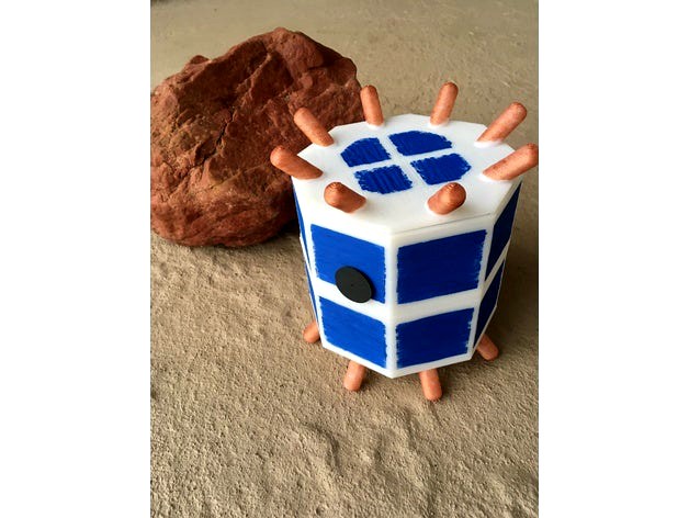
MINERVA
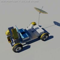
Micro/Nano Experimental Robot Vehicle for Asteroid
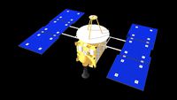
Before the European Space Agency (ESA) Rosetta mission's failed attempt to land Philae on Comet 67P/Churyumov-Gerasimenko captured our hearts and minds on 12 November 2014, another "lander" had been lost on a similar mission to an asteroid. This earlier mission was a joint Institute of Space and Astronautical Science (ISAS) of Japan and Japan Aerospace Exploration Agency (JAXA) MUSES-C technology verification mission ("HAYABUSA") which was launched on 9 May 2003. The goal of Hayabusa was to evaluate the ability to "collect samples from a small celestial body and to bring them back to the Earth." And this portion of the mission was successful, with the reentry of Hayabusa into the Australian desert on 13 June 2010.
NOTE: The final resting spot for the "lost" ESA Philae lander was discovered on 5 September 2016.
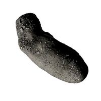
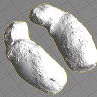
The asteroid that Hayabusa landed on was Itokawa (25143)--a small 535m x 294m x 209m hunk of stony S-type space rock. Prior to its initial touchdown on the asteroid, Hayabusa was scheduled to deploy a small rover/lander that was programmed to explore the surface of Itokawa. Known as MINERVA (Micro/Nano Experimental Robot Vehicle for Asteroid), this rover was incredibly small (120 mm x 100 mm; about the size of a lunchbox) and contained a unique propulsion system. Operating within the asteroid's micro-gravity environment, MINERVA was supposed to "hop" for mobility. This unusual movement was governed via a spinning turntable and two large flywheels. Although the pre-deployment telemetry from MINERVA was correct, the little rover was launched from Hayabusa on 12 November 2005 and was immediately "lost in space." The rover operated for over 18 hours following separation, but never reached the surface of Itokawa. Only a single image was transmitted from MINERVA along with a couple of 18+ hour data streams (e.g., voltage, photo-diode light intensity, and outside temperature). By studying these data ISAS and JAXA scientists determined that MINERVA was tumbling through space. In the words of one of the researchers, "MINERVA...became a small artificial satellite."
The Model
Due to the small size of MINERVA, this model is a life-size 1:1 scale model. Most of the internal scientific components have been reproduced except for the photo-diode sensors and orientation sensors. You can either glue these components together or "press fit" them together for maximum flexibility in disassembly and reassembly of your MINERVA model. Furthermore, the support structure inside MINERVA is made from several beams and clips that can be held together with #4-40 fasteners (NOTE: M3 fasteners should also work).
Parts
For building a complete life-size MINERVA, you will need to print the following parts:
Beam-Long (x10)
Beam-Short (x8)
Clips (x4)
Base (this part has built-in, disposable supports)
Upper Body
Top
Lip
Turntable
Comm
Flywheel (x2)
PC (x2)
Spindle (x4)
Torquer
Axle
Motor
Camera
Aperture
Condenser (x2)
Additionally, you will need:
Plastic Cement (recommended Testors Cement for Plastic Models # 3512 or Tamiya Extra Thin Cement #87038)
4-40 x 1/2 inch + nuts (x16)
4-40 x 3/4 inch + nuts (x12)
[M3 hardware may be substituted.]
Assembly Overview
Glue the Lip to the inside of the Top. Use the Upper Body as a guide for aligning the Lip.
Assemble the internal support structure using the photographs and drawing as a guide. Attach the Beams and Clips with either metal fasteners or plastic cement.
Carefully insert the internal support structure inside the Base and mark the center point of the Base floor. Remove the support structure and glue the Axle to this center point.
Glue the connector sides of the two PC parts together.
Carefully cut three (x3) Spindles to 60mm in length.
Insert these Spindles into the first three openings of the two cross support Beams. You can optionally glue these Spindles into place.
Glue the two Condensers together lengthwise with the electrodes topsy-turvy (end-to-end) from each other.
Attach the joined Condensers, Torquer, Flywheels, long Spindle, and Camera to the support structure and lower this assembly into the Base. Slip the Comm (Communications) component down alongside the structure end that is furthest away from the Aperture opening in the Upper Body.
Lay the Turntable on the Axle and insert the Motor beside the Turntable and inside the two lower support Beams.
Slide the Upper Body onto the Base and insert Aperture through the Upper Body (the Aperture should "plug" into the Camera body). Lay the joined PCs upside down on the internal support structure. Place the Top on your completed MINERVA model.
Enjoy.
References
You can download a FREE 3D-printable model of the asteroid Itokawa from NASA at:
https://nasa3d.arc.nasa.gov/detail/itokawa
Yoshimitsu, T., Kubota, T., Nakatani, I., Adachi, T., Saito, H., "Hopping Rover "MINERVA" for Asteroid Exploration," Pro. Fifth International Symposium on Artificial Intelligence, Robotics, and Automation in Space, June 1999, ESA SP-440; pgs. 83-88.
Yoshimitsu, T., Sasaki, S., Yanagisawa, M., Kubota, T., "Scientific Capability of MINERVA Rover in Hayabusa Asteroid Mission," Lunar and Planetary Science XXXV, 2004; 1517.pdf.
Yoshimitsu, T., Kubota, T., Nakatani, I., "MINERVA Rover Which Became a Small Artificial Solar Satellite," 20th Annual AIAA/USU Conference on Small Satellites, SSC06-IV-4
Hayabusa: A Technology Demonstrator for Sample and Return, Pamphlet; http://global.jaxa.jp/projects/sat/muses_c/
Micro/Nano Experimental Robot Vehicle for Asteroid
Before the European Space Agency (ESA) Rosetta mission's failed attempt to land Philae on Comet 67P/Churyumov-Gerasimenko captured our hearts and minds on 12 November 2014, another "lander" had been lost on a similar mission to an asteroid. This earlier mission was a joint Institute of Space and Astronautical Science (ISAS) of Japan and Japan Aerospace Exploration Agency (JAXA) MUSES-C technology verification mission ("HAYABUSA") which was launched on 9 May 2003. The goal of Hayabusa was to evaluate the ability to "collect samples from a small celestial body and to bring them back to the Earth." And this portion of the mission was successful, with the reentry of Hayabusa into the Australian desert on 13 June 2010.
NOTE: The final resting spot for the "lost" ESA Philae lander was discovered on 5 September 2016.
The asteroid that Hayabusa landed on was Itokawa (25143)--a small 535m x 294m x 209m hunk of stony S-type space rock. Prior to its initial touchdown on the asteroid, Hayabusa was scheduled to deploy a small rover/lander that was programmed to explore the surface of Itokawa. Known as MINERVA (Micro/Nano Experimental Robot Vehicle for Asteroid), this rover was incredibly small (120 mm x 100 mm; about the size of a lunchbox) and contained a unique propulsion system. Operating within the asteroid's micro-gravity environment, MINERVA was supposed to "hop" for mobility. This unusual movement was governed via a spinning turntable and two large flywheels. Although the pre-deployment telemetry from MINERVA was correct, the little rover was launched from Hayabusa on 12 November 2005 and was immediately "lost in space." The rover operated for over 18 hours following separation, but never reached the surface of Itokawa. Only a single image was transmitted from MINERVA along with a couple of 18+ hour data streams (e.g., voltage, photo-diode light intensity, and outside temperature). By studying these data ISAS and JAXA scientists determined that MINERVA was tumbling through space. In the words of one of the researchers, "MINERVA...became a small artificial satellite."
The Model
Due to the small size of MINERVA, this model is a life-size 1:1 scale model. Most of the internal scientific components have been reproduced except for the photo-diode sensors and orientation sensors. You can either glue these components together or "press fit" them together for maximum flexibility in disassembly and reassembly of your MINERVA model. Furthermore, the support structure inside MINERVA is made from several beams and clips that can be held together with #4-40 fasteners (NOTE: M3 fasteners should also work).
Parts
For building a complete life-size MINERVA, you will need to print the following parts:
Beam-Long (x10)
Beam-Short (x8)
Clips (x4)
Base (this part has built-in, disposable supports)
Upper Body
Top
Lip
Turntable
Comm
Flywheel (x2)
PC (x2)
Spindle (x4)
Torquer
Axle
Motor
Camera
Aperture
Condenser (x2)
Additionally, you will need:
Plastic Cement (recommended Testors Cement for Plastic Models # 3512 or Tamiya Extra Thin Cement #87038)
4-40 x 1/2 inch + nuts (x16)
4-40 x 3/4 inch + nuts (x12)
[M3 hardware may be substituted.]
Assembly Overview
Glue the Lip to the inside of the Top. Use the Upper Body as a guide for aligning the Lip.
Assemble the internal support structure using the photographs and drawing as a guide. Attach the Beams and Clips with either metal fasteners or plastic cement.
Carefully insert the internal support structure inside the Base and mark the center point of the Base floor. Remove the support structure and glue the Axle to this center point.
Glue the connector sides of the two PC parts together.
Carefully cut three (x3) Spindles to 60mm in length.
Insert these Spindles into the first three openings of the two cross support Beams. You can optionally glue these Spindles into place.
Glue the two Condensers together lengthwise with the electrodes topsy-turvy (end-to-end) from each other.
Attach the joined Condensers, Torquer, Flywheels, long Spindle, and Camera to the support structure and lower this assembly into the Base. Slip the Comm (Communications) component down alongside the structure end that is furthest away from the Aperture opening in the Upper Body.
Lay the Turntable on the Axle and insert the Motor beside the Turntable and inside the two lower support Beams.
Slide the Upper Body onto the Base and insert Aperture through the Upper Body (the Aperture should "plug" into the Camera body). Lay the joined PCs upside down on the internal support structure. Place the Top on your completed MINERVA model.
Enjoy.
References
You can download a FREE 3D-printable model of the asteroid Itokawa from NASA at:
https://nasa3d.arc.nasa.gov/detail/itokawa
Yoshimitsu, T., Kubota, T., Nakatani, I., Adachi, T., Saito, H., "Hopping Rover "MINERVA" for Asteroid Exploration," Pro. Fifth International Symposium on Artificial Intelligence, Robotics, and Automation in Space, June 1999, ESA SP-440; pgs. 83-88.
Yoshimitsu, T., Sasaki, S., Yanagisawa, M., Kubota, T., "Scientific Capability of MINERVA Rover in Hayabusa Asteroid Mission," Lunar and Planetary Science XXXV, 2004; 1517.pdf.
Yoshimitsu, T., Kubota, T., Nakatani, I., "MINERVA Rover Which Became a Small Artificial Solar Satellite," 20th Annual AIAA/USU Conference on Small Satellites, SSC06-IV-4
Hayabusa: A Technology Demonstrator for Sample and Return, Pamphlet; http://global.jaxa.jp/projects/sat/muses_c/
Similar models
3dwarehouse
free

Hayabusa Asteroid Orbiter
... asteroid orbiter
3dwarehouse
image modeling the spacecraft landed on the asteroid itokawa in japan #asteroid #hayabusa #orbiter
thingiverse
free

ITOKAWA iPhone4 Case by hemokosa
...kawa".http://darts.isas.jaxa.jp/planet/project/hayabusa/shape.plhttp://www.jaxa.jp/article/special/hayabusa_sp3/index_e.html
3dwarehouse
free
Asteroid Sample-return Spacecraft 'HAYABUSA' (MUSES-C)
...and return the sample to earth for further analysis. #hayabusa #japan #jaxa #musesc #nippon #science #seagate #space #space_craft
thingiverse
free
Asteroids for drinkers (sake jar and cups) by Kzysh0851
... version.
ryugu cups and stands: 162173 ryugu scaled one in twenty thousand, by tato_713https://www.thingiverse.com/thing:4278016
cg_trader
$50
Asteroid Itokawa
... itokawa
cg trader
asteroid itokawa 3d asteroid itokawa belt space, formats include obj, fbx, c4d, ready for 3d animation and ot
cults
free
Itokawa
...okawa shape model v1.0. hay-a-amica-5-itokawashape-v1.0. nasa planetary data system, 2008
author/origin: doug ellison / nasa-jpl
thingiverse
free
Philae lander by brainfloat
...ur of the esa rosetta mission i've created a miniature model of the philae lander to explore alien landscapes closer to home.
3d_export
$10
Lunar Rover 3D Model
...over 3d model
3dexport
lunar rover lander moon buggy vehicle mission space exploration
lunar rover 3d model korbul 10857 3dexport
thingiverse
free

Asteroid Itokawa by RTicknor
...asteroid itokawa by rticknor
thingiverse
models from nasa pds asteroid/dust archives. http://sbn.psi.edu/pds/archive/shape.html
grabcad
free

LUNAR LANDER
...lunar lander
grabcad
esa
Themindseye
thingiverse
free
The Voyage of the Bathysphere by themindseye
...the voyage of the bathysphere by themindseye
thingiverse
a 3d replica of the 1934 bathysphere with presentation plaque.
thingiverse
free
Ped101 by themindseye
... time, and temperature displays).
the complete project code and assembly details can be found at:
http://how2-oh.github.io/ped101
thingiverse
free

ThinkFun Plate Expansion Kit by themindseye
...nd 4x4 (large) for thinkfun maker studio. this thing is one part of a three part expansion kit series: brackets, plates, threads.
thingiverse
free
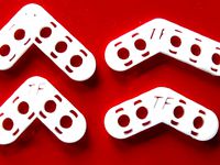
ThinkFun Bracket Expansion Kit by themindseye
...egree 2x3, 130-degree 2x2, and 130+-degree 2x3. this is one part of a three part expansion kit series: brackets, plates, threads.
thingiverse
free

Weather Box by themindseye
...her box is about 100+ days.
you can find the electronics building instructions and arduino code at:
how2-oh.github.io/weather-box
thingiverse
free

piOneer by themindseye
...t was featured in issue #50 of the magpi magazine:https://raspberrypi.org/magpi-issues/magpi50.pdf
[this is a free pdf download.]
thingiverse
free

ThinkFun Threads Expansion Kit by themindseye
...and printer variance might require increasing (e.g., nuts) 1-3% and decreasing (e.g., threaded parts) 1-3% sizes for optimal fit.
thingiverse
free
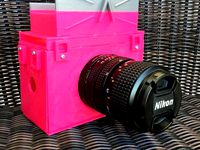
AIRflex by themindseye
...y pink? as acknowledgment of breast cancer awareness month, the airflex was printed in magenta pla with a silver pla accent band.
thingiverse
free

The Thankful Turkey by themindseye
..."feathered" thanks
note: the thankful turkey is an adaptation of a commercial product, "turkey on the table."
thingiverse
free

Greeting Knob by themindseye
...torials/accelerated-aging-your-metal-bearing-3d-prints
note: greeting knob is pull handle and not an operating cylinder doorknob.
Minerva
design_connected
$29

Minerva
...minerva
designconnected
poliform minerva computer generated 3d model. designed by colombo, carlo.
3ddd
free
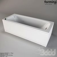
MINERVA 170
...minerva 170
3ddd
formina , ванна
bathtub minerva
3ddd
$1

Giorgetti - Poltrona Minerva
... poltrona minerva
http://divani.webmobili.it/p-77521-minerva-giorgetti-poltrone-.html
turbosquid
$29

Poliform Minerva
... available on turbo squid, the world's leading provider of digital 3d models for visualization, films, television, and games.
3ddd
free
Natuzzi Saturno & Minerva
...& minerva
3ddd
natuzzi , saturno & minerva
natuzzi saturno & minerva
3ddd
$1
Christopher Guy MINERVA
...stopher guy minerva
3ddd
minerva , christopher guy
высота: 64см
длина: 85см
ширина: 74см
3ddd
$1

Стол Minerva
...ilik
стол итальянской компании silik. выполнен в программе 3d max,8 + v-ray 1.5. элементы стола смоделированы с помощью сплайнов.
3ddd
$1
Silik Minerva
... silik
сервант silik minerva (art. 991)
ширина: 2240 мм
глубина: 590 мм
высота: 2520 мм
сервант без наполнения (вазы,статуэтки)
3ddd
$1
Globo Minerva 6834-9D
...globo minerva 6834-9d
3ddd
globo
globo minerva 6834-9d
3ddd
$1

Riperlamp Minerva 274A
...люстра пр-ва riperlamp. размеры соответствуют оригиналу, проработка довольно высокая. материалы не прикладываю, .obj в комплекте.