Thingiverse
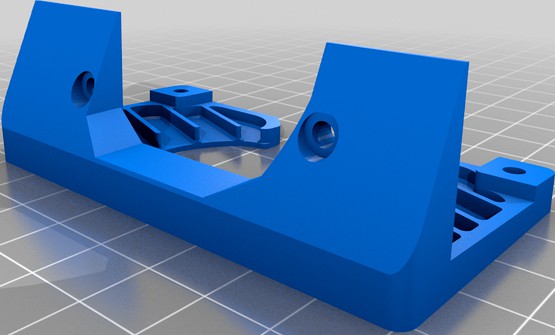
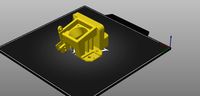
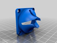
Microswiss Direct-Drive Mosquito Mount and Shroud 2 by susop
by Thingiverse
Last crawled date: 3 years ago
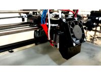
This design was created because I bought a micro-swiss direct drive and later upgraded my hot end to a Slice mosquito. I didn't want to throw out my microswiss for a bondtech extruder motor, so I made this design. This new version features two 5015 part cooling fans, and re-uses the stock filament runout sensor for a no-compromises CR-10S modification. For hardware, I designed the shroud around several kits of metric internal-wrenching hex-headed metric screws I already had on-hand. If you are starting from scratch, I counted-up the following:
18 square M3 nuts
1ea 30mm M3 screw
8ea 20mm M3 screw
3ea 16mm M3 screws
2ea 9mm-10mm M3 screws
8ea 8mm M3 screw
2ea stock filament sensor housing screws (the bevel-headed ones)
2ea 6mm M2.5 Screws (optional, but may increase rigidity. The included mosquito fan screws will work if you purchased the mosquito with a fan)
2ea M3 8mm stock curve-headed hot end cage mount screws
2ea stock spool adapter screws
2ea M5 20mm screws
2ea M5 t-slot nuts
E3D extruder mount adapter for Slice Mosquito
Slice Mosquito hot end sock (a 24v nozzle heater will not be able to overcome the power of the 5015 fans)
Spare bowden tube
If you're upgrading from a CR-10 with no filament sensor, you can just buy a spare X-axis endstop switch and it'll work, along with 2ea M3 screws of any reasonable size.
Zipties
For printing, delete all supports for the square M3 nut gaps. If you forget, it'll take forever to clean out. I was not able to delete the need for all supports, so use your best judgement. The "Bottom" file is a bit slanted. This is because my MicroSwiss bracket has a slant to it. Without adjusting for this slant, my shroud kept hitting the bed clips or the bed heater strain relief.
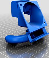
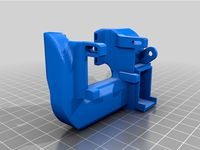
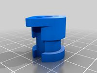
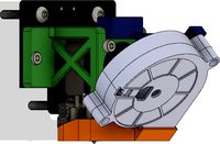
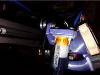
For assembly, the exploded view pictures should get you 99% of the way there. I ended up sanding both top and bottom of the Filament Switch Pivot to ensure it can freely pivot without being pinched. The center sleeve is slightly taller than the pivot, but I still found the pivot would bind initially. I also had to remove some material from the slice E3D adapter to allow the mount hardware to pass through. The best way to do this is to mount the adapter onto the heatsink, then pre-install the hot end by sandwiching it in-between the Right body and the E3D rear mount, then drill through the mount holes to ream the adapter until you see two groves cut into it. Go slow or you'll likely cut more plastic than metal. Looking through the mosquito mount holes, they should be full circles and unobstructed. For those who like to have adventures when assembling Ikea furniture, have fun and good luck! For everybody else, below are the recommended assembly steps:
Test-mount mosquito with just the Rear E3D Mount block and two screws. This is to approximate the length of bowden tube. Do a rough size estimation, remove hot end, insert the cut bowden tube, re-affix the assembly onto the direct drive mechanism with the bowden fed into the hole, then trim excess in an upside-down "V" shape to match the two extruder gears. Remove the hot end again, the slightly ream out the entrance to the bowden tube to make it less likely the filament will hang up on the lip of the tube as it is fed by the extruder gears. Be careful not to allow debris from the bowden tube to enter into tube itself and down into the nozzle.
Remove the extruder motor, then pre-position the backplate and install square nuts into the backplate. Reinstall all extruder motor hardware except the bottom left screw.
Insert nozzle heater and thermistor onto the heat block, then install the sock.
Insert the Mosquito assembly into the Right body and sandwich it with the Rear E3D mount. (Optional) install the Mosquito fan mount screws in the lower mount holes (smaller than the main mount screws for the E3D mount). This is optional because the main mount method is to sandwich the E3D mount. The mosquito fan mount screws may provide extra rigidity as a secondary means of connecting the heatsink with the printed shroud.
Install the assembly onto the Microswiss Direct Drive. Ensure all hardware mounting the assembly to the direct drive remains loose.
Pre-route all wiring as-necessary, and install all square nuts on the assembly so far (except the top right mount nut for the 40mm fan). Install the left body in a way that ensures the wiring stays within the channel and is not pinched.
Fully tighten all mount hardware between the assembly and the direct drive. Then insert the top right mount nut for the 40mm fan.
Install both 5015 fans and route wiring accordingly. The front screws for the fans cannot be installed yet. The Left Fan Mount Spacer is shaped like a teardrop to act like a handle for installation. It can be oriented either up or down.
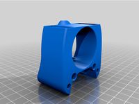
Install the hot end 40mm fan and shroud. Insert the square nuts and install the final two 5015 mount screws
Install the "Bottom" part cooling fan plate.
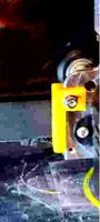
(optional) Install the Filament Switch Armature, Filament Switch, Filament Switch Center Sleeve, Filament Switch Pivot, Filament Switch Cover, and Spool Adapter (to the top of the frame). All hardware can be tightly installed except the Filament Switch Pivot/Sleeve thru-pin. The Filament Center Sleeve and Pivot will be mounted with a thru-bolt and square nut. The square nut will ride in a channel that allows for left/right adjustment. The spool adapter will align your spool in a straight line similar to a Prusa, and allow full print volume up to 400mm Z-axis.
Snug the thru-bolt and check for Filament Switch Pivot freedom of movement. If it doesn't move freely, remove it and sand the top and bottom again. Reinstall and repeat until tightening the thru-bolt does not bind the Filament Switch Pivot.
With the Filament Switch thru-bolt loose, load filament until it is just past the gears. Slide the Filament Switch Pivot until it just barely actuates the filament switch. Tighten the thru-pin, and check to make sure the filament switch actuates the switch when loaded, and de-actuates the switch when unloaded. This may take a few tries to get perfect. If your machine doesn't tell you when the switch is actuated or not, use a multimeter or continuity light to indicate actuation.
Test a few prints. To test filament switch actuation, clip the filament during a print. Once it stops, load new filament and resume print. After the print is finished, look for skin artifacting and tighten X-Axis belt as-needed. After 25 printing hours, re-tighten all hardware. Re-tighten again after 100 printing hours. This re-torques the printed "Right" body around the E3D adapter as the shroud relaxes and better conforms to the shape of the metal E3D Adapter.
For machine settings, I use X-min -44, X-max 38.5, Y-min -21.2, Y-max 24, Gantry Height 35mm.
I don't plan on any future updates to this design, but if you find you cannot get the filament runout switch rigging just-right, submit a comment and I'll alter the throw of the armature to actuate the switch more aggressively. I didn't have problems with mine, so I'm hoping the current version works for everybody.
18 square M3 nuts
1ea 30mm M3 screw
8ea 20mm M3 screw
3ea 16mm M3 screws
2ea 9mm-10mm M3 screws
8ea 8mm M3 screw
2ea stock filament sensor housing screws (the bevel-headed ones)
2ea 6mm M2.5 Screws (optional, but may increase rigidity. The included mosquito fan screws will work if you purchased the mosquito with a fan)
2ea M3 8mm stock curve-headed hot end cage mount screws
2ea stock spool adapter screws
2ea M5 20mm screws
2ea M5 t-slot nuts
E3D extruder mount adapter for Slice Mosquito
Slice Mosquito hot end sock (a 24v nozzle heater will not be able to overcome the power of the 5015 fans)
Spare bowden tube
If you're upgrading from a CR-10 with no filament sensor, you can just buy a spare X-axis endstop switch and it'll work, along with 2ea M3 screws of any reasonable size.
Zipties
For printing, delete all supports for the square M3 nut gaps. If you forget, it'll take forever to clean out. I was not able to delete the need for all supports, so use your best judgement. The "Bottom" file is a bit slanted. This is because my MicroSwiss bracket has a slant to it. Without adjusting for this slant, my shroud kept hitting the bed clips or the bed heater strain relief.
For assembly, the exploded view pictures should get you 99% of the way there. I ended up sanding both top and bottom of the Filament Switch Pivot to ensure it can freely pivot without being pinched. The center sleeve is slightly taller than the pivot, but I still found the pivot would bind initially. I also had to remove some material from the slice E3D adapter to allow the mount hardware to pass through. The best way to do this is to mount the adapter onto the heatsink, then pre-install the hot end by sandwiching it in-between the Right body and the E3D rear mount, then drill through the mount holes to ream the adapter until you see two groves cut into it. Go slow or you'll likely cut more plastic than metal. Looking through the mosquito mount holes, they should be full circles and unobstructed. For those who like to have adventures when assembling Ikea furniture, have fun and good luck! For everybody else, below are the recommended assembly steps:
Test-mount mosquito with just the Rear E3D Mount block and two screws. This is to approximate the length of bowden tube. Do a rough size estimation, remove hot end, insert the cut bowden tube, re-affix the assembly onto the direct drive mechanism with the bowden fed into the hole, then trim excess in an upside-down "V" shape to match the two extruder gears. Remove the hot end again, the slightly ream out the entrance to the bowden tube to make it less likely the filament will hang up on the lip of the tube as it is fed by the extruder gears. Be careful not to allow debris from the bowden tube to enter into tube itself and down into the nozzle.
Remove the extruder motor, then pre-position the backplate and install square nuts into the backplate. Reinstall all extruder motor hardware except the bottom left screw.
Insert nozzle heater and thermistor onto the heat block, then install the sock.
Insert the Mosquito assembly into the Right body and sandwich it with the Rear E3D mount. (Optional) install the Mosquito fan mount screws in the lower mount holes (smaller than the main mount screws for the E3D mount). This is optional because the main mount method is to sandwich the E3D mount. The mosquito fan mount screws may provide extra rigidity as a secondary means of connecting the heatsink with the printed shroud.
Install the assembly onto the Microswiss Direct Drive. Ensure all hardware mounting the assembly to the direct drive remains loose.
Pre-route all wiring as-necessary, and install all square nuts on the assembly so far (except the top right mount nut for the 40mm fan). Install the left body in a way that ensures the wiring stays within the channel and is not pinched.
Fully tighten all mount hardware between the assembly and the direct drive. Then insert the top right mount nut for the 40mm fan.
Install both 5015 fans and route wiring accordingly. The front screws for the fans cannot be installed yet. The Left Fan Mount Spacer is shaped like a teardrop to act like a handle for installation. It can be oriented either up or down.
Install the hot end 40mm fan and shroud. Insert the square nuts and install the final two 5015 mount screws
Install the "Bottom" part cooling fan plate.
(optional) Install the Filament Switch Armature, Filament Switch, Filament Switch Center Sleeve, Filament Switch Pivot, Filament Switch Cover, and Spool Adapter (to the top of the frame). All hardware can be tightly installed except the Filament Switch Pivot/Sleeve thru-pin. The Filament Center Sleeve and Pivot will be mounted with a thru-bolt and square nut. The square nut will ride in a channel that allows for left/right adjustment. The spool adapter will align your spool in a straight line similar to a Prusa, and allow full print volume up to 400mm Z-axis.
Snug the thru-bolt and check for Filament Switch Pivot freedom of movement. If it doesn't move freely, remove it and sand the top and bottom again. Reinstall and repeat until tightening the thru-bolt does not bind the Filament Switch Pivot.
With the Filament Switch thru-bolt loose, load filament until it is just past the gears. Slide the Filament Switch Pivot until it just barely actuates the filament switch. Tighten the thru-pin, and check to make sure the filament switch actuates the switch when loaded, and de-actuates the switch when unloaded. This may take a few tries to get perfect. If your machine doesn't tell you when the switch is actuated or not, use a multimeter or continuity light to indicate actuation.
Test a few prints. To test filament switch actuation, clip the filament during a print. Once it stops, load new filament and resume print. After the print is finished, look for skin artifacting and tighten X-Axis belt as-needed. After 25 printing hours, re-tighten all hardware. Re-tighten again after 100 printing hours. This re-torques the printed "Right" body around the E3D adapter as the shroud relaxes and better conforms to the shape of the metal E3D Adapter.
For machine settings, I use X-min -44, X-max 38.5, Y-min -21.2, Y-max 24, Gantry Height 35mm.
I don't plan on any future updates to this design, but if you find you cannot get the filament runout switch rigging just-right, submit a comment and I'll alter the throw of the armature to actuate the switch more aggressively. I didn't have problems with mine, so I'm hoping the current version works for everybody.
Similar models
thingiverse
free

Prusa i3 Hexagon Bowden mount by liu_d
...cs due to the increased airflow restriction in this mount.
it uses 23mm square (m4) mounting hole spacing for the carriage mount.
thingiverse
free

E3d Fan Duct Rattle Proof by 616Engineering
...laces the machine screw that crack and break the plastic with m3 screws and nuts.
necessary hardware
6x m3 nuts
6x shcs m3 x 20
thingiverse
free
40MM Fan & BLTouch Mount for FLSUN Cube by Cmerritt_319
...sults just using the stock z limit switch and the leveling screws.
print quality will improve dramatically once you install this.
thingiverse
free

Bowden adapter for GRRF hot-end with fan and pneufit connection by Tubograve
...fan that you find into old computer (60mm)
-the grrf hot-end
-some m3 screws and nuts
-the pneufit connection for bowden
bella.
thingiverse
free
CR6-SE MiniMe Direct Drive Mosquito Mount by charkear
...for a bowden style setup with an e3d mount similar to my other projects posted on...
thingiverse
free
I'm No Hero - Hot End Fan Shroud
...use the stock part fan or add the adapter and add a 40x40x10 fan. i may build an offset mount for the stock abl when i have time.
grabcad
free

BMG Adapter.
... to be experimented with. there are adapters for using both the mirrored and non-mirrored versions of the bondtech bmg extruder.
thingiverse
free
Mosquito Hot End Groove Mount Adapter - Bondtech QR by RepRapTodd
...r extruder. 1.75mm filament. recommend using capricorn xs ptfe bowden tubing to interface between the mosquito and bondtech qr.
thingiverse
free
Eryone Mosquito Mount and Fan Duct - Thinker S, Thinker SE, ER-20 by eight_heads
...m2.5 x ~20mm mosquito mount through heatsink fan to mosquito(front)
2@ m2.5 x ~10mm mosquito to mosquito bowden connector/adapter
thingiverse
free

Sapphire PRO Mosquito Hotend mount by Mr_Helpmann
...bs. it probably works just as well with petg.
no supports needed.
i will continue to make and publish improvements to the design.
Susop
thingiverse
free

Creality CR-10 Bed Lock Knobs by susop
...y equivalent to .25mm or .001" of bed height.
i bought an assorted metric square nuts kit made by kinpar and sold on amazon.
thingiverse
free

Microswiss Direct-Drive Mosquito Mount and Shroud by susop
... verify if petg will hold up, but if you wrap your heat block with a thermal sock like i did, i'd imagine petg would be fine.
Microswiss
thingiverse
free

Microswiss Ender 3 by Joferval
...microswiss ender 3 by joferval
thingiverse
microswiss direct drive adapter for ender 3
thingiverse
free

Precision Piezo Orion Microswiss clamp by Moriquendi
...nted parts required to use the orion with a microswiss hotend.
i have not personally tested these parts with a microswiss hotend.
thingiverse
free
VORON printhead for MicroSwiss hotend by phil245
...3d v6 hotend but i do have the microswiss so i set to making it fit.
i hope this helps someone, if it does please post a make.
thingiverse
free

BLTouch adjuster for Ender 3 with MicroSwiss hotend
... adjuster for ender 3 with microswiss hotend
thingiverse
bl touch (creality version) adjuster for ender 3 with microswiss hotend
thingiverse
free
Microswiss X Axis Endstop for DirectDrive by ericthetazman
... by ericthetazman
thingiverse
i made this to account for new position of x endstop with microswiss direct drive on my longer lk4
thingiverse
free

microswiss dd cr10s pro by deshi
...thingiverse
modified for the ender 3 microswiss dd to fit cr10s pro.
had to raise bed 5mm set x axis off set to -35 and y to -25
thingiverse
free

CR-10S fan nozzle for microswiss hotendf by jfmvoers
...hotendf by jfmvoers
thingiverse
cooling nozzle for a creality cr10s with microswiss hotend.also fits on other creality printers.
thingiverse
free
Satsana Ender 3 v2 MicroSwiss 5010 by Annikamint
...giverse.com/thing:4787797/files
and
https://www.thingiverse.com/thing:4647053 to fit on ender 3 v2 with microswiss and 5010 fan
thingiverse
free
ender 3 v2 bltouch microswiss by Mampo112
...sured 1.4mm shorter than creality stock hotend.
use m3 screws to fit it.
thats my first post in thingiverse
sorry my poor english
thingiverse
free

CR10 / Ender2 Microswiss Fang by 2bedom
...all metall 300°c microswiss hotend.
(https://store.micro-swiss.com/products/all-metal-hotend-kit-for-cr-10)
the fang fits good ..
Mosquito
design_connected
$16

Mosquito
...mosquito
designconnected
rex kralj mosquito computer generated 3d model. designed by kralj, niko.
3d_export
$5

Mosquito
...of some place that is destroyed or abandoned long ago. with such models the application would top the charts and prove its worth.
turbosquid
$100

Mosquito
... available on turbo squid, the world's leading provider of digital 3d models for visualization, films, television, and games.
turbosquid
$22
mosquito
... available on turbo squid, the world's leading provider of digital 3d models for visualization, films, television, and games.
turbosquid
$20

Mosquito
... available on turbo squid, the world's leading provider of digital 3d models for visualization, films, television, and games.
turbosquid
$15

mosquito
... available on turbo squid, the world's leading provider of digital 3d models for visualization, films, television, and games.
turbosquid
$3
Mosquito
... model mosquito for download as 3ds, obj, fbx, blend, and dae on turbosquid: 3d models for games, architecture, videos. (1311331)
3d_export
$25

mosquito
...mosquito
3dexport
simple rendering of the scene file
3d_export
$10
Mosquito 3D Model
...mosquito 3d model
3dexport
mosquito insect bug hexapod flyer
mosquito 3d model def 19400 3dexport
archive3d
free

Mosquito 3D Model
...archive3d
mosquito gnat insect
mosquito - 3d model (*.gsm+*.3ds) for exterior 3d visualization.
Shroud
3d_export
$500

Centrifugal pump volute casing with impeller
...casing with impeller 3dexport volute casing with impeller and shroud ...
3d_export
$35
The Holy Face base relief 3D Model
...the holy face base relief 3d model 3dexport shroud turin veronica veronica's veil gospel ikon jesus holy face...
3d_export
$20
present car cloth presentation transport transportation shape concepts show celebration cover showro
...transportation shape concepts show celebration cover showroom covered revealin shroudd cover covering tarp draped fabric cloth showroom reveal revealing...
3d_export
$5

Lockheed F-117 Nighthawk lowpoly stealth bomber
...initial operating capability status in 1983. the aircraft was shroudd in secrecy until it was revealed to the public...
3d_export
$49
kriss vector gen 2 sub-d
...rear flip sight.<br>- vector ejection port.<br>- vector crb square shroud / 16"" sliencer.<br>- ds150 stock.<br>- .ma (maya 2020 ascii)<br>-...
3d_export
$10

vichy dining table
...in oak, sycamore and walnut marquetry.<br>even if the restaurant shroud the vichy in a long table cloth, two slender...
3d_export
$500

us navy pcu sterett ddg-104 arleigh burke class destroyer flight iia max
...the position has been shifted.<br>q. where are the exhaust shroud for the stacks?<br>a. since ddg-89, the exhaust system was...
thingiverse
free

shroud by samshay317
...shroud by samshay317
thingiverse
shroud
thingiverse
free

Fan Shroud
...fan shroud
thingiverse
this is a fan shroud for a 140mm fan
thingiverse
free
40mm fan shroud
...40mm fan shroud
thingiverse
40mm fan shroud
Direct
design_connected
free
Compas Direction
...compas direction
designconnected
free 3d model of compas direction by vitra designed by prouvé, jean.
design_connected
$18

Direction Pivotant
...direction pivotant
designconnected
vitra direction pivotant computer generated 3d model. designed by prouvé, jean.
turbosquid
$6
not direct the front
...oyalty free 3d model not direct the front for download as max on turbosquid: 3d models for games, architecture, videos. (1213034)
turbosquid
$10

Rails Direct
... available on turbo squid, the world's leading provider of digital 3d models for visualization, films, television, and games.
3d_export
$5

Picto toilet directions
...lude 3d files next to rhino6: x3dv, step, igus, obj and stl. double-sided, flipping changes the gender directions to the toilets.
3ddd
$1
fauteuli direction
...d
chair , vitra , fauteuli
fauteuli vitra chair
design_connected
$18

Fauteuil Direction, 1951
...fauteuil direction, 1951
designconnected
vitra fauteuil direction, 1951 computer generated 3d model. designed by prouvé, jean.
3d_export
$5
Directional tactile 3D Model
...tactile 3d model
3dexport
directional tactile braille tile flooring interior
directional tactile 3d model renob000 71068 3dexport
turbosquid
$26

Radio direction finder A
...ty free 3d model radio direction finder a for download as fbx on turbosquid: 3d models for games, architecture, videos. (1212490)
turbosquid
$7

Wooden direction signage
...ty free 3d model wooden direction signage for download as max on turbosquid: 3d models for games, architecture, videos. (1453747)
Drive
3d_export
$10

cycloidal drive
...cycloidal drive
3dexport
cycloidal drive
3d_ocean
$5
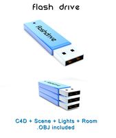
Flash Drive
...h drive included : – materials – scene ( lighs / room ) – .c4d + .obj for any questions please feel free to contact me thank you.
3d_ocean
$5
Usb drive
...s shaders and a lighting setup. it also has a small animation of it going in and out. i saved it out as both a .blend file and...
3d_ocean
$5

Pen Drive
...est computer drive game model good low poly new pen pen drive textured unwrapped uv very low poly
a very beautiful low poly model
3d_ocean
$10
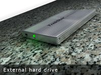
External hard drive
... is a detailed model of a trekstor external hard drive. you can easily modify the label on the top. simply edit the text objects.
turbosquid
$1

Flash Drive
...quid
royalty free 3d model flash drive for download as blend on turbosquid: 3d models for games, architecture, videos. (1231573)
turbosquid
$10
Flash Drive
...id
royalty free 3d model usb flash drive for download as obj on turbosquid: 3d models for games, architecture, videos. (1325282)
turbosquid
$1
USB Drive
...
royalty free 3d model usb drive for download as obj and fbx on turbosquid: 3d models for games, architecture, videos. (1701787)
3d_ocean
$4
USB Flash Drive
...usb flash drive
3docean
computer disk drive electronic flash mac memory pc pen usb
usb flash drive. the cartridge form
turbosquid
$10

Flash Drive
...y free 3d model flash drive for download as lxo, lxo, and obj on turbosquid: 3d models for games, architecture, videos. (1551742)
Mount
3d_export
free

mounting bracket
...mounting plate is the portion of a hinge that attaches to the wood. mounting plates can be used indoors, cabinetry and furniture.
turbosquid
$2

MOUNTING
... available on turbo squid, the world's leading provider of digital 3d models for visualization, films, television, and games.
turbosquid
free

Mounts
... available on turbo squid, the world's leading provider of digital 3d models for visualization, films, television, and games.
turbosquid
free

Mount Fuji
...fuji
turbosquid
free 3d model mount fuji for download as obj on turbosquid: 3d models for games, architecture, videos. (1579977)
3d_export
$5

Headphone mount LR
...headphone mount lr
3dexport
headphone mount l+r
turbosquid
$39

Mount rainier
...quid
royalty free 3d model mount rainier for download as fbx on turbosquid: 3d models for games, architecture, videos. (1492586)
turbosquid
$5

pipe mounting
...quid
royalty free 3d model pipe mounting for download as obj on turbosquid: 3d models for games, architecture, videos. (1293744)
turbosquid
$3

Mounting Tires
...uid
royalty free 3d model mounting tires for download as fbx on turbosquid: 3d models for games, architecture, videos. (1708511)
3d_export
$5

Magnetic GoPro Mount
...pro mount
3dexport
cool magnetic mount for gopro. allows you to mount the camera on flat metal surfaces and get exclusive shots.
turbosquid
$5

Stone Mount
...ty free 3d model stone mount for download as ma, obj, and fbx on turbosquid: 3d models for games, architecture, videos. (1370306)
2
design_connected
$11
No 2
...no 2
designconnected
sibast no 2 computer generated 3d model. designed by sibast, helge.
turbosquid
$99

Smilodon 2 Pose 2
... available on turbo squid, the world's leading provider of digital 3d models for visualization, films, television, and games.
turbosquid
$20
Barrel Barricade 2-2
... available on turbo squid, the world's leading provider of digital 3d models for visualization, films, television, and games.
turbosquid
$6
Wall Trophy (2) (2)
... available on turbo squid, the world's leading provider of digital 3d models for visualization, films, television, and games.
turbosquid
free
Tire label 2 of 2
... available on turbo squid, the world's leading provider of digital 3d models for visualization, films, television, and games.
3ddd
$1

Кровать, 2 тумбочки, 2 светильника
...кровать, 2 тумбочки, 2 светильника
3ddd
кровать, 2 тумбочки, 2 светильника
нормальное качество
формат 3ds max
без текстур
3ddd
free

Кровать, 2 тумбочки, 2 светильника
...кровать, 2 тумбочки, 2 светильника
3ddd
кровать, 2 тумбочки, 2 светильника
нормальное качество
формат 3ds max
без текстур
turbosquid
$19
Loft wooden square box chandelier (2) (2) (2)
... available on turbo squid, the world's leading provider of digital 3d models for visualization, films, television, and games.
3ddd
$1
ALPEREN-2
...alperen-2
3ddd
комод , alperen-2
комод с зеркалом alperen-2
design_connected
$27

Confluences 2 2-Seater Sofa
... 2-seater sofa
designconnected
ligne roset confluences 2 2-seater sofa computer generated 3d model. designed by nigro, philippe.