Thingiverse
MIA 3D Printer Micro - Fabrikator Mini II Revamp for Higher Precision and Ease Of Calibration by MIAMicroFlight
by Thingiverse
Last crawled date: 3 years ago
A 3D printer design I am working on as time permits reusing some of the mechanical parts of a Turnigy Mini II 3D printer.
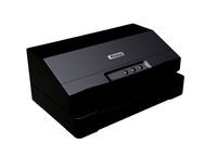
My very first 3D printers were a couple Fabrikator Mini II, I bought for prototyping quickly small parts. I made a lot of great parts on them, after making some upgrades to improve the precision, but leveling the table on such tiny enclosed machines was always tedious and the hex socket screws used to level the table were not deep enough for the hex key to engage in them, and geting to them inside the enclosure was a task!. So I decided to gut all the components and make them work around my own design.
I still have the other Fabrikator Mini II for nostalgic reasons. I was going to sell them almost new for 1/2 the price, but I really like the original design except for the hard to level and acces the hot end issues.
Bear in mind this is my first 3D printer design "revamp" and a good test of the part quality of my new Anycubic I3 Mega that is making all the 3D printed parts for this revamped project. So far so good!
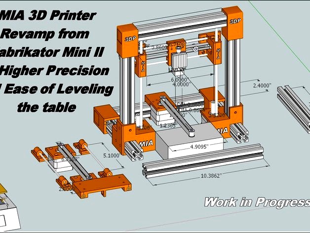
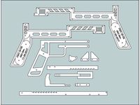
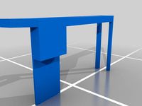
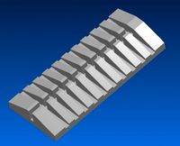
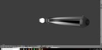
This started with a logical placement of the given stock mechnical parts with a machine style in the tradition of the very early industrial types of CNC routers and Mills with the work bed Y axis front to back for logical ease of accesing parts and working on the machine, but in miniature. However, once I had the main parts printed and assembled with the extrussion, I began to see some areas that could have been done simpler and since I really like the Anycubic I3 mega, layout, I decided to rearrange the parts and go with a similar layout, thus the new drawing. The base is done in 4 sections, it is a bolt on assembly, the top wth the rail supports part of the upper 3D printed plate, two sides and a bottom. This will double for the Y rail support and be the enclosure for the electronics nice and neat just likle the Anycubic I3.
Nov 11, 2017 - Project Start
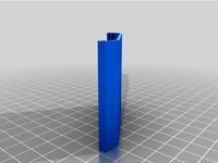
Currently, I am printing the Y axis Liner support base, this is taking most of the platform on the Anycubic I3 mega. I printed this with no bottom fill but with a 25% fill for the rest of the part, this was done to make the thickness of t this part honeycomb like, for strength yet lighteness.
The square aluminum extrusion I am using for the frame and some of the 3D printed parts may seem overkill on such a small machine, but I learned long ago that if you are going to build a precision machine you have to start with a solid framework. The T-Slot aluminum extrusion I am using is 1"x1" but one could replace such with a square 1/16 wall alu tube of same outside dimensions. The T-Slot is nice since things can be attached more easily at any given point along its length without having to drill though the tube. One could also use precision square wood made from bass -oak. But the T-slot extrussion offers the best precision and rigidity. There are no micro precision 3D printers on the market, at leat not since the last time I researched it, and since I have the materials and tools, I decided to dive into this project and make it to my own needs.
MIA 3D Printer Micro SPECIFICATION:
High Rigidity and Precision
Logical
Simple
Easy Access
Easy Leveling
Use Aluminum T-Slot Extrusion with 3D Printed Parts
Design around Stock Fabrikator Mini II Mechanics and Electronics
Why I really decided to do this :
Well, I had some T-Slot 1x1" alumium extrusions waiting for a neat project and so I decided to design the structure around these extrusions. The original Fabrikator Mini II is very rigid and is done in anodized blue aluminum enclosure, on some models, so this was the nice part, but acces sto the build table and for maintenance and calibration ? not very user friendly. Otherwise, it is a nice little machine that outputs some fairly decent parts, when calibrated properly. But to make a more precise and easy to acccess and adjust micro 3D printer, capable of printing on same 100x100x100mm working area, I decided to take on this task.
The 3D Printed parts are being printed on an Anycubi I3 Mega 3D printer for precision and right now there is still a few parts that need to be made and tweaked, but it is looking great!. I will post more photos, files, as projects continues.
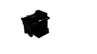
Nov 12, 2017 - New Cad Layout
New CAD Photo Uploaded. I have made some changes to the base, just to get the item printed and try it for fit, in real time. The idea with the base is to get it done in 3 printed parts, each is small enough to fit on the Anycubic I3, Mega , better if you have a larger printer. The Base "skirt" has provisions for screw mounting via posts part of the skirt that alow the top and bottom to be screwed on. I did this for ease of acces to the base. It also has perforations at the front and at the back for air flow to the electronics which will be installed inside. The "skirt" part of the base is also integral with the front panel, and I did this to establish a solid conplete rectangle support (the "skirt"). This also has a couple side tabs that screw onto the side base posts of the gantry tower. Very similar to the way the Anycubic I3 is done, so no brainer here, except customization of the base for the Fab Mini II guts.
I also finished the upper Z axis support posts, these are floating, meaning they are able to slide on the Alu horizontal upper frame extrussion and allow for side adjustment, for parallelism.
I have most of the framework assembled and waiting on the base "skirt" to finish printing so that I can assemble the base with the Y axis. The Y axis at the top of the base was tested and it moves nice and smooth, but I had to modify the linear sliding rail to clear the belt buckle under it. The top of the base, the one with the integral Y Axis rail supports was printed as one piece, as the stl file shows, but I had a bit of warpage on the ends since the thickness is still dense at M6 or 0.250" thick with infill of 25%, I may do this part in two section, and go with the rail supports as separate pieces over a G10 1/8" thick sheet. Much like I plan on doing the base bottom from G10 as we do not need the thickness for a bottom plate, just a thin cover for the base enclosure. M2 or 1/16" thick Aluminum would be the other option. But I got plenty G10 in various thicknesess so I will probably use that. We'll see once I have the base skirt printed and assembled with the top.
The Z and X axis was also tested and it slides nice and smootth with very little setting of the 3D printed parts.
...More to come...
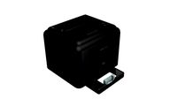
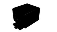
November 13, 2017 - Real Product Photos
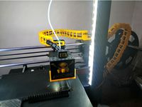
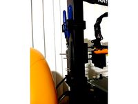
New Real Product Photos uploaded. I had to redo the Z Axis in view that the stock Fabrikator Mini II Belt is too short for the distance of the independent Z axis rods and Blocks. I was going to cut the stock belt to get an exra 1" of length, but I decided not to do this. The new Z Axis block is all in one piece but may flex due to loosing the front bulk as the independent Z blocks have in order to access easier the screws for the Y Axis motor. However, I can alwwas go back to the independent Z Blocs with a longer belt which is faily cheap. I just need to order one that has the same width and teeth spec. Anyway, I wanted to upload real product photos so viewers can see how the actual product is coming along and how the Anycubic I3 Mega printed the parts. First prototype asssembly is always a must, because it allows one to see the physical model and any areas that may need tweaking. It normally takes me 3 attempts to get from concept to finish and tested product.
I did not spend too much time on the electronic board fit, in CAD, but this is going to be a bit challenging fitting it in the smaller base, with easy access to the SD Card and USB slots on the side, as the original Fabrikator Mini II has, but other options were considered.
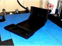
November 15, 2017 - Heated Bed Platform
The actual build of this revamp design has allowed me to redesign the heated bed better. I am going to make an auxiliary aluminum frame to support the existing Fab II hot plate and this will ride over a G10 thick plate that will mount to the 3D printed part, both for support and insulation from the hot plate. This will also have a larger footprint by 1" around the perimeter of the hot plate so that the leveling hardware can clear the hot end at the very extremes of the build platform, be neatly hidden under it and be easily adjustable. A glass table has been also considered as the Anycubic I3 Has. If I could get a hold a miniature size "Ultrabase" it would be awesome!
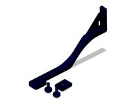
November 24, 2017 - Z Axis Boots
I addded the boots that hold the Z axis rods in place over the base blocks. These boots have a glove fit tolerance for the Z rods and have 2 perforations that mate with the base blocks using M4 screws in a self threading manner right into the plastic base to hold them in place.
My very first 3D printers were a couple Fabrikator Mini II, I bought for prototyping quickly small parts. I made a lot of great parts on them, after making some upgrades to improve the precision, but leveling the table on such tiny enclosed machines was always tedious and the hex socket screws used to level the table were not deep enough for the hex key to engage in them, and geting to them inside the enclosure was a task!. So I decided to gut all the components and make them work around my own design.
I still have the other Fabrikator Mini II for nostalgic reasons. I was going to sell them almost new for 1/2 the price, but I really like the original design except for the hard to level and acces the hot end issues.
Bear in mind this is my first 3D printer design "revamp" and a good test of the part quality of my new Anycubic I3 Mega that is making all the 3D printed parts for this revamped project. So far so good!
This started with a logical placement of the given stock mechnical parts with a machine style in the tradition of the very early industrial types of CNC routers and Mills with the work bed Y axis front to back for logical ease of accesing parts and working on the machine, but in miniature. However, once I had the main parts printed and assembled with the extrussion, I began to see some areas that could have been done simpler and since I really like the Anycubic I3 mega, layout, I decided to rearrange the parts and go with a similar layout, thus the new drawing. The base is done in 4 sections, it is a bolt on assembly, the top wth the rail supports part of the upper 3D printed plate, two sides and a bottom. This will double for the Y rail support and be the enclosure for the electronics nice and neat just likle the Anycubic I3.
Nov 11, 2017 - Project Start
Currently, I am printing the Y axis Liner support base, this is taking most of the platform on the Anycubic I3 mega. I printed this with no bottom fill but with a 25% fill for the rest of the part, this was done to make the thickness of t this part honeycomb like, for strength yet lighteness.
The square aluminum extrusion I am using for the frame and some of the 3D printed parts may seem overkill on such a small machine, but I learned long ago that if you are going to build a precision machine you have to start with a solid framework. The T-Slot aluminum extrusion I am using is 1"x1" but one could replace such with a square 1/16 wall alu tube of same outside dimensions. The T-Slot is nice since things can be attached more easily at any given point along its length without having to drill though the tube. One could also use precision square wood made from bass -oak. But the T-slot extrussion offers the best precision and rigidity. There are no micro precision 3D printers on the market, at leat not since the last time I researched it, and since I have the materials and tools, I decided to dive into this project and make it to my own needs.
MIA 3D Printer Micro SPECIFICATION:
High Rigidity and Precision
Logical
Simple
Easy Access
Easy Leveling
Use Aluminum T-Slot Extrusion with 3D Printed Parts
Design around Stock Fabrikator Mini II Mechanics and Electronics
Why I really decided to do this :
Well, I had some T-Slot 1x1" alumium extrusions waiting for a neat project and so I decided to design the structure around these extrusions. The original Fabrikator Mini II is very rigid and is done in anodized blue aluminum enclosure, on some models, so this was the nice part, but acces sto the build table and for maintenance and calibration ? not very user friendly. Otherwise, it is a nice little machine that outputs some fairly decent parts, when calibrated properly. But to make a more precise and easy to acccess and adjust micro 3D printer, capable of printing on same 100x100x100mm working area, I decided to take on this task.
The 3D Printed parts are being printed on an Anycubi I3 Mega 3D printer for precision and right now there is still a few parts that need to be made and tweaked, but it is looking great!. I will post more photos, files, as projects continues.
Nov 12, 2017 - New Cad Layout
New CAD Photo Uploaded. I have made some changes to the base, just to get the item printed and try it for fit, in real time. The idea with the base is to get it done in 3 printed parts, each is small enough to fit on the Anycubic I3, Mega , better if you have a larger printer. The Base "skirt" has provisions for screw mounting via posts part of the skirt that alow the top and bottom to be screwed on. I did this for ease of acces to the base. It also has perforations at the front and at the back for air flow to the electronics which will be installed inside. The "skirt" part of the base is also integral with the front panel, and I did this to establish a solid conplete rectangle support (the "skirt"). This also has a couple side tabs that screw onto the side base posts of the gantry tower. Very similar to the way the Anycubic I3 is done, so no brainer here, except customization of the base for the Fab Mini II guts.
I also finished the upper Z axis support posts, these are floating, meaning they are able to slide on the Alu horizontal upper frame extrussion and allow for side adjustment, for parallelism.
I have most of the framework assembled and waiting on the base "skirt" to finish printing so that I can assemble the base with the Y axis. The Y axis at the top of the base was tested and it moves nice and smooth, but I had to modify the linear sliding rail to clear the belt buckle under it. The top of the base, the one with the integral Y Axis rail supports was printed as one piece, as the stl file shows, but I had a bit of warpage on the ends since the thickness is still dense at M6 or 0.250" thick with infill of 25%, I may do this part in two section, and go with the rail supports as separate pieces over a G10 1/8" thick sheet. Much like I plan on doing the base bottom from G10 as we do not need the thickness for a bottom plate, just a thin cover for the base enclosure. M2 or 1/16" thick Aluminum would be the other option. But I got plenty G10 in various thicknesess so I will probably use that. We'll see once I have the base skirt printed and assembled with the top.
The Z and X axis was also tested and it slides nice and smootth with very little setting of the 3D printed parts.
...More to come...
November 13, 2017 - Real Product Photos
New Real Product Photos uploaded. I had to redo the Z Axis in view that the stock Fabrikator Mini II Belt is too short for the distance of the independent Z axis rods and Blocks. I was going to cut the stock belt to get an exra 1" of length, but I decided not to do this. The new Z Axis block is all in one piece but may flex due to loosing the front bulk as the independent Z blocks have in order to access easier the screws for the Y Axis motor. However, I can alwwas go back to the independent Z Blocs with a longer belt which is faily cheap. I just need to order one that has the same width and teeth spec. Anyway, I wanted to upload real product photos so viewers can see how the actual product is coming along and how the Anycubic I3 Mega printed the parts. First prototype asssembly is always a must, because it allows one to see the physical model and any areas that may need tweaking. It normally takes me 3 attempts to get from concept to finish and tested product.
I did not spend too much time on the electronic board fit, in CAD, but this is going to be a bit challenging fitting it in the smaller base, with easy access to the SD Card and USB slots on the side, as the original Fabrikator Mini II has, but other options were considered.
November 15, 2017 - Heated Bed Platform
The actual build of this revamp design has allowed me to redesign the heated bed better. I am going to make an auxiliary aluminum frame to support the existing Fab II hot plate and this will ride over a G10 thick plate that will mount to the 3D printed part, both for support and insulation from the hot plate. This will also have a larger footprint by 1" around the perimeter of the hot plate so that the leveling hardware can clear the hot end at the very extremes of the build platform, be neatly hidden under it and be easily adjustable. A glass table has been also considered as the Anycubic I3 Has. If I could get a hold a miniature size "Ultrabase" it would be awesome!
November 24, 2017 - Z Axis Boots
I addded the boots that hold the Z axis rods in place over the base blocks. These boots have a glove fit tolerance for the Z rods and have 2 perforations that mate with the base blocks using M4 screws in a self threading manner right into the plastic base to hold them in place.
Similar models
thingiverse
free
Anycubic i3 MEGA Z shield spacer by ppicault
...cape on the high part of the printer.
you have to print 2 parts for a full cover of the surface.
ready to use gcode is available.
thingiverse
free

Second Z axis endstop handle for Anycubic i3 Mega by mjedlinski
...3 mega, you should follow this topic:https://www.lesimprimantes3d.fr/forum/topic/9051-double-endstop-axe-z-modification-officiel/
thingiverse
free
Z axis endstop screw holder for Anycubic I3 Mega by Ziarni89
... axis endstop screw holder for anycubic i3 mega by ziarni89
thingiverse
a little holder for z-endstop screw of anycubic i3 mega.
thingiverse
free

Anycubic i3+ part bed engine by goku666
...ve my first 3d printer anycubic i3+ and one part of this printer is broken, so decide to project this part. mayby someone help :)
thingiverse
free
Cable chain hotend and z Axis Anycubic I3 mega (mega s) by VSLab
...so i decided to redesign everything myself. i hope you enjoy it, for any possible issues you comment and i will give you support.
thingiverse
free
Anycubic i3-Mega Schutz Z-Achse by Jerks
...e frame of the anycubic i3 mega to prevent the cables etc. of the printhead get stuck on the z-axis or get stuck under the frame.
grabcad
free

Anycubic i3 Mega NÄVLINGE Lampholder
...
a 3d-printed holder to mount the ikea clamp lamp nävlinge on the z-frame of the anycubic i3 mega printer.
created with freecad!
thingiverse
free
AnyCubic Mega i3 - Side Extruder Support by Alpharic
...mount to a z motor?
nop in this moment . i put the same way like my delta printer,
if someday is going wrong i will let you know,
thingiverse
free
Anycubic I3 Mega Z-Axis Camera Mount C920/Tripod Screw by Aerocalculus
... cameras that have a camera tripod screw mount, such as logitech c920.
i would advice against mounting heavy cameras like a dslr.
grabcad
free

SD Card Support for Anycubic i3 Mega S
...mega s
grabcad
sd card support for anycubic i3 mega s. i designed this support to put the sd card reader on front of the printer
Miamicroflight
thingiverse
free
Anycubic I3 Mega Repositionable Tool Holder Blocks by MIAMicroFlight
...ier or cura, as you wish to arange the blocks on your machine.
please let me know if you find it useful by liking or commenting.
thingiverse
free

MIA LED LAMP Ver 1.0 for ANYCUBIC I3 MEGA by MIAMicroFlight
...k is more practical. it still provides plenty light around the work area . i have other lamp designs but have to tweak the files.
thingiverse
free
Rubber Band Gun OGG P201 Ai-Oh, Wood, 10 rounds - Revamped for 3D Print by MIAMicroFlight
...t this link:http://oggcraft.jp/eng/eng_howto_aioh_1.html
but if you have questions as to the build. i'd be happy to help you.
Revamp
3d_export
$13
wooden three seater sofa
...stand out in your home among-st all your furniture. revamp your living space with this wooden...
thingiverse
free
Wearables Revamped by mmueller43
...wearables revamped by mmueller43
thingiverse
using new skills on an old project.
thingiverse
free

Akupara Revamped by childishlindino
.... i also changed what it was floating on to make it feel like it was more in space, as you can see by the crescent moon and star.
thingiverse
free
Champion Gundyr Revamped by Mahantzu
...champion gundyr revamped by mahantzu
thingiverse
smoothed version of the original in stl format and pre-supported chitubox file
thingiverse
free
Lenovo Y700 Laptop Stand Revamp by vestorlockwood
...00 laptop stand revamp by vestorlockwood
thingiverse
an easier to assemble lenovo y700 laptop stand. disk drive fits underneath.
renderosity
$5

Revamped OceanWave
...gt;
textures<br />
<br />
48 hair textures<br />
<br />
this product requires oceanwave hair</p>
renderosity
$8

Revamped Impressive
...for the corset<br />
06 mat poses for the pantie<br />
<br />
option to hide the straps and/or clips.</p>
thingiverse
free

drone toper for lisam frame revamped. by YeahButItWorks
...d. by yeahbutitworks
thingiverse
i made this for my lislam frame. it works good and has kept together through some nasty crashes
sketchfab
$20
E-11 Revamp 4K textures
...he trouble. for star wars jedi knight academy!
weaponshd project - e-11 revamp 4k textures - buy royalty free 3d model by rooxon
thingiverse
free

Revamped inner pin for retaining clip by Joe_Snuffy
... middle helps them actually snap in like the oem part. i think this change will only be good if you can print flexible material.
Fabrikator
turbosquid
free

Fabrik / factory - 4
... available on turbo squid, the world's leading provider of digital 3d models for visualization, films, television, and games.
turbosquid
free

Fabrik / factory - 3
... available on turbo squid, the world's leading provider of digital 3d models for visualization, films, television, and games.
turbosquid
free
Fabrik / factory - 2
... available on turbo squid, the world's leading provider of digital 3d models for visualization, films, television, and games.
turbosquid
free
Fabrik / factory - 1
... available on turbo squid, the world's leading provider of digital 3d models for visualization, films, television, and games.
3ddd
$1
IKEA FABRIK&#214;R ИКЕЯ ФАБРИКОР
...32/#/70240332
ширина: 57 см
глубина: 47 см
высота: 150 см
макс нагрузка на полку: 10 кг
фабрикор
шкаф-витрина
7 999.–
3ddd
$1
Serenissima / Settanta
...гко редактировать, вся информация по размерамhttp://www.belleveder.com/katalog/po-fabrike/serenissima/catalogo_settanta
3d_export
$10
V6 engine
... the first v6 engines were designed and produced independently by marmon motor car company, deutz gasmotoren fabrik and delahaye.
thingiverse
free

Mini Fabrikator Window by hyppyayo
...mini fabrikator window by hyppyayo
thingiverse
laserd window for mini fabrikator!
thingiverse
free
Nema 23 (fabrikator) by albo86
...nema 23 (fabrikator) by albo86
thingiverse
the stepper motor which operates the extruder of turnigy fabrikator
thingiverse
free

Fabrikator mini v2 Fan by christophe94
...fabrikator mini v2 fan by christophe94
thingiverse
fabrikator mini v2 fan
Mia
3ddd
$1
Mdfitalia Mia
...dfitalia mia armchair
mdfitalia mia sofa
mdfitalia mia pouf
factory: mdfitalia
model: miahttp://www.mdfitalia.it
3ddd
free
Frighetto / Mia
...ighetto , mia
фабрика "frighetto"
модель "mio"
размеры 520x545x890mm
turbosquid
$198

Mia Superhero
... available on turbo squid, the world's leading provider of digital 3d models for visualization, films, television, and games.
turbosquid
$45
Cartoon Mia
... available on turbo squid, the world's leading provider of digital 3d models for visualization, films, television, and games.
turbosquid
$29
Mia (Max)
... available on turbo squid, the world's leading provider of digital 3d models for visualization, films, television, and games.
turbosquid
$29

Mia (OBJ)
... available on turbo squid, the world's leading provider of digital 3d models for visualization, films, television, and games.
turbosquid
$5
Mia Karaffe
... available on turbo squid, the world's leading provider of digital 3d models for visualization, films, television, and games.
3ddd
$1
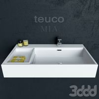
Умывальник Teuco Mia
...меситель
умывальник teuco из коллекции mia.
модель включает в себя умывальник, смеситель, и декор.
в файле файлы 14й и 11й версии
design_connected
free

ALESSI Mia and Tua Pitchers
...alessi mia and tua pitchers
designconnected
free 3d model of alessi mia and tua pitchers
turbosquid
$149

Cartoon Girl Mia
... available on turbo squid, the world's leading provider of digital 3d models for visualization, films, television, and games.
Calibration
turbosquid
$15
DEFIBRILLATOR CALIBRATORS
... available on turbo squid, the world's leading provider of digital 3d models for visualization, films, television, and games.
turbosquid
$3
Calibration Test Benches
...libration test benches for download as 3ds, obj, c4d, and fbx on turbosquid: 3d models for games, architecture, videos. (1355804)
turbosquid
$79
Tag Heuer Monaco Calibre 11
...free 3d model tag heuer monaco calibre 11 for download as max on turbosquid: 3d models for games, architecture, videos. (1634427)
turbosquid
$50
Smith & Wesson 50 Calibre Magnum
... available on turbo squid, the world's leading provider of digital 3d models for visualization, films, television, and games.
3d_export
$10
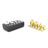
Laboratory Calibration Weight Set 1 3D Model
... 3d model
3dexport
laboratory lab science equipment weight set
laboratory calibration weight set 1 3d model bessoo 88084 3dexport
3d_export
$15
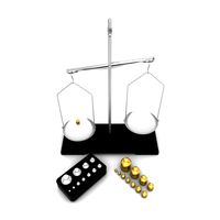
Laboratory Scale and Calibration Weight Set 3D Model
...port
laboratory lab science equipment weight set scale
laboratory scale and calibration weight set 3d model bessoo 88203 3dexport
3d_export
$5
3D printer filament calibration tool 3D Model
...ernier
3d printer filament calibration tool 3d model download .c4d .max .obj .fbx .ma .lwo .3ds .3dm .stl locoman 107942 3dexport
3d_export
$59
tag heuer link calibre 16 watch
...built to real-world scale. units used: centimeters. model is 18 centimeters tall.<br>scene objects are organized by groups.
3d_export
free
laser height reference calibration tool opt lasers
...ind out more about the engraving and cutting laser heads, this item was designed to work with, take a look at the following page:
3d_export
$99
Patek Philippe White Gold Calibre 89
...br>please note: this 3d model like all my other models cannot be used as nft, as is or modified<br>thank you for reading
Ease
3ddd
$1

Sofa EASE
...ofa ease.paola lenti | aqua collection. upholstered round sofa with removable cover , design by francesco rota. size ∅180х55h см.
turbosquid
$19
Sink Ease MF-40-17S
...d model sink ease mf-40-17s for download as max, obj, and fbx on turbosquid: 3d models for games, architecture, videos. (1194761)
turbosquid
$19
Sink Ease MA-40-40S
...d model sink ease ma-40-40s for download as max, obj, and fbx on turbosquid: 3d models for games, architecture, videos. (1194786)
3d_export
$5

painter ease
...aterials are logically named<br>the main format is in 3ds max 2009.<br>satisfcation garranteed..<br>thank you !
3d_export
$12
VECNA mask stranger things
...stranger things 3dexport it is cut for your greater ease of...
3d_export
$20

Luzik
...will be more so far my dear full of ease ...
3d_export
$5
office cubicle empty
...and a filing cabinet fully textured and unwrapped for ease of use if you want to change the...
3d_export
free

robot for animation
...type. parent objects have also been added here, for ease of...
3d_ocean
$4

Animated Robot for games
...for games 3d model robot for you games. exporte easey to unity realised with...
3d_export
$39
Classic Motorbike oH 3D Model
...motorbike the individual parts have been linked together for ease use and materials applied nice 3ds max realistic sexy...
Micro
3ddd
$1
Micro
...micro
3ddd
автобус
turbosquid
$80

MICRO
...ty free 3d model micro for download as max, c4d, obj, and fbx on turbosquid: 3d models for games, architecture, videos. (1700743)
3ddd
$1

JBL Micro Wireless
... micro , колонка , плеер
jbl micro wireless
turbosquid
$10
Suppressor Micro
...quid
royalty free 3d model suppressor micro for download as on turbosquid: 3d models for games, architecture, videos. (1380433)
turbosquid
$20
Micro Meter
...osquid
royalty free 3d model micro meter for download as fbx on turbosquid: 3d models for games, architecture, videos. (1350448)
turbosquid
$7
NIghtstand Micro
...d
royalty free 3d model nightstand micro for download as max on turbosquid: 3d models for games, architecture, videos. (1248117)
3ddd
$1
Micro wind turbine
...micro wind turbine
3ddd
турбина
micro wind turbine for your green building projects
turbosquid
$29
Micro Speakers
... available on turbo squid, the world's leading provider of digital 3d models for visualization, films, television, and games.
turbosquid
$29

Micro Servo.max
... available on turbo squid, the world's leading provider of digital 3d models for visualization, films, television, and games.
turbosquid
$20

Micro cells
... available on turbo squid, the world's leading provider of digital 3d models for visualization, films, television, and games.
Ii
3d_ocean
$5
inoplanet II
...inoplanet ii
3docean
3ds arman3dg games ii inoplanet low max poly trees
inoplanet ii
3ddd
$1

Novecento II
...novecento ii
3ddd
консоль
консоль: ii novecento
дизайнер: elia monterosso
3ddd
$1

Спальня VENERO II
...d
venero ii , venero , hulsta
спальня venero ii
3ddd
$1
PROPORTION II
...proportion ii
3ddd
malabar emotional
консоль proportion ii
malabar emotional design
коллекция euphoria
3ddd
$1
Regina II
...ltrona frau , капитоне
this is a custom version of the poltrona frau regina ii armchair.
3d_export
$119

cinderella ii
...cinderella ii
3dexport
3d_export
$119

lara ii
...lara ii
3dexport
3d_export
$119

doris ii
...doris ii
3dexport
3ddd
$1
Heracleum II
...s endless technical possibilities,
making this new version much more efficient while providing unique and sparkling illumination.
3ddd
$1

Towel Collection II
...towel collection ii
3ddd
полотенце
towel collection ii
Higher
turbosquid
$7

Ladder Low-Poly and Higher-Poly
...y and higher-poly for download as 3ds, obj, fbx, dae, and stl on turbosquid: 3d models for games, architecture, videos. (1482547)
3d_export
$8

wood house
...house 3dexport this model for 3ds max 2012 and higher winrar 4.10 and higher. corona render. fbx , obj...
3d_export
$5
garden furniture
...tiss company. this model for 3ds max 2012 and higher winrar 4.10 and higher. corona render. obj and mtl...
3d_ocean
$5
Ready for render scene
...or higher. need : 3d studio max 2013 or higher v-ray 2.4 or higher, v-ray physical camera with d.o.f....
3d_export
free

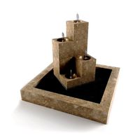
fountain 03
...fountain 03 3dexport 3ds max 2013 and higher ...
3d_export
free
fountain 04
...fountain 04 3dexport 3ds max 2013 and higher ...
3d_ocean
$12

Corona materials + render scene
...stage setting materials corona materials for v. 1.2.1 and higher + render scene all textures repetitive max2011 and higher...
3d_export
$5

modern office table
...3dexport modern office table for 3d max 2014 or higher with...
3d_export
$13

rugs - collection
...v-ray with 3ds max. max *.max - 2010 or higher v-ray *.max - 3.6 or...
3ddd
$1
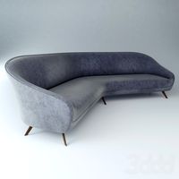
ItalianSofa_unknownDesign
..., classical , cleandesign unknown design from expensive interior, higher subdivision...
Precision
turbosquid
$40
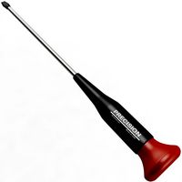
Precision Screwdriver
...model precision screwdriver for download as 3ds, max, and obj on turbosquid: 3d models for games, architecture, videos. (1301545)
cg_studio
$59

Precision mountain3d model
...n mountain3d model
cgstudio
.max - precision mountain 3d model, royalty free license available, instant download after purchase.
turbosquid
$10
Lazer Precision rifle
...lty free 3d model lazer precision rifle for download as blend on turbosquid: 3d models for games, architecture, videos. (1313439)
3d_export
$7
Precision Indicator
...includes all scene, lighting, cameras, materials and textures. many file formats are available. the visuals are in 4k resolution.
turbosquid
$59

Dell Precision 7510 Laptop
... dell precision 7510 laptop for download as max, fbx, and obj on turbosquid: 3d models for games, architecture, videos. (1678133)
turbosquid
$45
11 Precision Metals Bldg03
... available on turbo squid, the world's leading provider of digital 3d models for visualization, films, television, and games.
turbosquid
$37

Kelly Wearstler Precision bench
... available on turbo squid, the world's leading provider of digital 3d models for visualization, films, television, and games.
turbosquid
$18
Kelly Wearstler Precision table
... available on turbo squid, the world's leading provider of digital 3d models for visualization, films, television, and games.
3d_export
$60
Fender Precision Bass 3D Model
...uitar frets instrument electric bassguitar 4string rock blues pop music
fender precision bass 3d model rendersteel 86834 3dexport
3d_export
$5

precision centrifugal pump
...ceed 180℃ and the inlet pressure does not exceed 0.8mpa.<br>drawings can only be used as a reference for mechanical design!
Mini
turbosquid
$10
Mini Mini Luceplan
...
royalty free 3d model mini mini luceplan for download as max on turbosquid: 3d models for games, architecture, videos. (1227359)
3d_ocean
$39

Mini Cooper
...mini cooper
3docean
cabrioler cooper mini
mini cooper cabrioler
3d_export
$30

Mini lathe
...mini lathe
3dexport
mini lathe
3d_export
$5

mini mouse
...mini mouse
3dexport
mini mouse
3d_export
$5
mini house
...mini house
3dexport
mini house
3d_export
free

Mini Mecha
...mini mecha
3dexport
concept of mini mecha
3d_ocean
$20
Mini Gun
...mini gun
3docean
gatling gun gun machine gun mini gun weapon
model of a mini gatling gun.
3ddd
free
Herve mini
... кофейный , herve
http://www.mobiliavenanti.it/ru/products/hervè-mini
3d_export
$5
mini wall
...mini wall
3dexport
mini wall for living room
3d_export
$5

mini bank
...mini bank
3dexport
mini bank 3d model
Printer
archibase_planet
free
Printer
...inter
archibase planet
printer laser printer pc equipment
printer n120614 - 3d model (*.gsm+*.3ds) for interior 3d visualization.
archibase_planet
free
Printer
...rchibase planet
laser printer office equipment computer equipment
printer - 3d model (*.gsm+*.3ds) for interior 3d visualization.
turbosquid
$100

Printer
...er
turbosquid
royalty free 3d model printer for download as on turbosquid: 3d models for games, architecture, videos. (1487819)
turbosquid
$3
Printer
...turbosquid
royalty free 3d model printer for download as max on turbosquid: 3d models for games, architecture, videos. (1670230)
turbosquid
$1
printer
...turbosquid
royalty free 3d model printer for download as max on turbosquid: 3d models for games, architecture, videos. (1595546)
turbosquid
$1
printer
...turbosquid
royalty free 3d model printer for download as max on turbosquid: 3d models for games, architecture, videos. (1595105)
turbosquid
$10
Printer
...id
royalty free 3d model printer for download as max and 3dm on turbosquid: 3d models for games, architecture, videos. (1607146)
turbosquid
$7
Printer
...royalty free 3d model printer for download as ma, ma, and obj on turbosquid: 3d models for games, architecture, videos. (1644580)
turbosquid
$30
Printer
... available on turbo squid, the world's leading provider of digital 3d models for visualization, films, television, and games.
turbosquid
$20
Printer
... available on turbo squid, the world's leading provider of digital 3d models for visualization, films, television, and games.