GrabCAD

Mechanical Flaps RASSOR Drum Design
by GrabCAD
Last crawled date: 2 years ago
Section Diameter= 450mm
Drum Diameter = 450mm
Drum length = 350 mm
Mass= 4.5 kg
Material= Aluminum/Aluminum alloy, Delrin
Fill ratio = 75 - 80%
Fill volume = 50000 cm^3, 50 liters
Maximum engaged length = 150mm
The flaps design is a system of active regolith flow direction by way of bi-direcional flaps located inboard of each toothed intake channel. The flaps are driven by crank arms connected to the flap on a sliding pivot joint. The crank arms are connected to a central drive axle. When the drive axle rotates, the crank arms first move the flaps into either the intake or dumping position. For intake, the flaps rotate such that they face inward, promoting a regolith inflow. The drum itself is not directly driven by the drive shaft, rather is mechanically linked to the flap mechanism. When the flaps move to the inflow position, they eventually hit a mechanical hardstop. When this happens, the torque from the drive axle is transferred to the entire drum.
To release regolith, the axle reverse rotational direction. The drum, no longer driven by the flap mechanism, stops rotating. The flaps, driven by the crank arms move to point outwards, promoting an outflow of regolith. Once the flaps hit the outflow hardstops, the torque is once again transferred to the drum and the entire system rotates in the opposite direction to dump its contents.
The goal of the active flap control design is to make the regolith flow direction actively controlled. The intent is to minimize regolith losses in passive systems like gravity driven flow control or geometric flow control. By having the intake direction control system dependent on the direction of the rotation, a more concrete (certain) mechanically driven flow control is achieved.
Similar models
grabcad
free

Excav8
...e way and unload when turning the other way. the pathway itself is designed to optimize the fill ratio and flow rate of the drum.
grabcad
free

NASA Bucket Drum Design Challenge
...d. the internal swirl moves the regolith back out through the scoop buckets.
this scooping drum was designed to be 3d printed.
grabcad
free

NASA Bucket Drum Design Challenge V4
...oth mining, discharging and scooping).
the max volume it can collect 15.5 litters
the drum was design so it can be 3d printed.
grabcad
free

RASSOR Drum Design 2.1
...direction is reversed which makes storage drum to rotate along with scoops.
a working animation of the design can be found here-
grabcad
free

NASA Bucket Drum Design Challenge V2
...drum as an exploded view it should be 3d printed (file > nasa bucket drum design challenge v2 drum assm.stl) as a single unit.
grabcad
free

Linked Rotating Buckets for NASA Regolith Challenge
...cal volume of regolith based on design constraints is 57.3 liters)
regolith volume to assembly volume ratio: 47.84/1.612 = 29.68
grabcad
free

Motor Driving P.P Unit
... rotation angle of the driven pulley are the same)
3. the workpiece returned from the conveyor is transferred to the next process
grabcad
free

Volume Control Damper...
...volume control damper...
grabcad
this is used to control the inflow and outflow of air in a building.
grabcad
free

Pedal Crank Arm
...et, allowing the rider to apply force to the pedal transferred via the crank arm to the forward gears to drive the bicycle chain.
grabcad
free

Crank-driven four-group parallel four-rods mechanism
...the four driven shafts have the same rotation direction and speed. this principle can be used in the design of multi-axis drills.
Rassor
grabcad
free

RASSOR
...rassor
grabcad
just tried to design rassor
hope you like it :)
grabcad
free

Rassor
...s effesien used for mining in outer space, the system used is the mortar mixing system. this drum rassor uses horizontal rotation
grabcad
free

Rassor
...rassor
grabcad
modeling of rassor drums for the collection of extraterrestrial soil. rhinoceros, file stl and renderings
grabcad
free

Rassor Bucket
...rassor bucket
grabcad
nasa rassor challenge
grabcad
free

RASSOR
... (rassor) with major highlight is the excavation blade is a angle of 30 degree. the software used in particle simulation is edem
grabcad
free

RASSOR
...rassor
grabcad
this is a very simple and innovative plan
grabcad
free

RASSOR Regolith Miner
...rassor regolith miner
grabcad
designed for the nasa rassor bucket challenge
grabcad
free

rassor de Alonso
...rassor de alonso
grabcad
eta es una pala para el sistema rassor
grabcad
free

RASSOR Scoop Drum
...rassor scoop drum
grabcad
stl / jpeg / txt file submission for nasa rassor scoop challenge
grabcad
free

NASA RASSOR BUCKET
... is a design for nasa rassor bucket. the total weight of the bucket is 4.94 kg. for unloading rotate the bucket counterclockwise.
Drum
3d_export
$5

drums
...drums
3dexport
drums
3d_ocean
$20

Drums
...iled model of drums. charleston,bass drum, tamtam drums, cymbal,etc. available in .blend, .obj, and .lwo format. ready for render
archibase_planet
free

Drum
...hibase planet
drum musical instrument tambour drum kit
drum taiko n091115 - 3d model (*.gsm+*.3ds) for interior 3d visualization.
design_connected
$9

Drum
...drum
designconnected
brent comber drum computer generated 3d model. designed by comber, brent.
turbosquid
$4
Drum 7 Drum 12
... model drum 7 drum 12 for download as max, max, fbx, and obj on turbosquid: 3d models for games, architecture, videos. (1641795)
3d_export
$15

Conga Drum
...conga drum
3dexport
conga drums
3d_export
$10
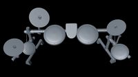
electro drums
...electro drums
3dexport
electro drums
3d_export
$5
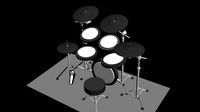
electric drums
...electric drums
3dexport
electric drums
turbosquid
$1

Drum
...turbosquid
royalty free 3d model drum for download as blend on turbosquid: 3d models for games, architecture, videos. (1480093)
turbosquid
$1

Drums
...s
turbosquid
royalty free 3d model drums for download as max on turbosquid: 3d models for games, architecture, videos. (1240112)
Flaps
design_connected
$27

Flap
...flap
designconnected
edra flap computer generated 3d model. designed by binfaré, francesco.
3ddd
$1

стол Flap
...стол flap
3ddd
стол flap дизайнера камира рашида
3ddd
$1
полотенцесушитель an-trax it FLAPS
...rax it flaps , полотенцесишитель
полотенцесушитель an-trax it flaps
размеры 1710х350мм
turbosquid
$20

pneumatic flap
...model pneumatic flap for download as dxf, ige, stl, and sldas on turbosquid: 3d models for games, architecture, videos. (1410890)
3ddd
$1
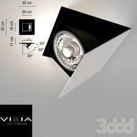
Vibia Flap
... flap
встроеный светильник фирмы vibia
всраиваетса в потолок и стены и поворачиваетса под тремя углами- 45,60,90 градусов
turbosquid
$100
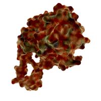
Flap Endonuclease
... available on turbo squid, the world's leading provider of digital 3d models for visualization, films, television, and games.
turbosquid
$8
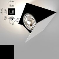
Vibia Flap
... available on turbo squid, the world's leading provider of digital 3d models for visualization, films, television, and games.
archive3d
free
Flap 3D Model
...flap 3d model
archive3d
media flap - 3d model for interior 3d visualization.
3ddd
free

Flip-Flap
...flip-flap
3ddd
подсолнух
модель для хорошего настроения! всем удачи)
3ddd
free

Flip-flap toy
... флип флап , игрушка
3ds max 2009, v-ray 2.10.01
8012 poly
Mechanical
3d_export
$50

Mechanism
...mechanism
3dexport
mechanism -------- animation is present only in the blender file.
3d_export
$5

mechanics
...mechanics
3dexport
turbosquid
$50

mechanic
... available on turbo squid, the world's leading provider of digital 3d models for visualization, films, television, and games.
3ddd
$1
Mechanical Wasp
...mechanical wasp
3ddd
робот
mechanical wasp
3d_export
$20
Mechanical tail
...mechanical tail
3dexport
mechanical tail<br>four-part movement
3d_export
$5
mechanical ballista
...mechanical ballista
3dexport
a mechanical ballista useful for medieval or fantasy games does not contain animations
turbosquid
$59

Mechanical Part
...id
royalty free 3d model mechanical part for download as c4d on turbosquid: 3d models for games, architecture, videos. (1410833)
turbosquid
$50

Mechanical Spider
...royalty free 3d model mechanical spider for download as blend on turbosquid: 3d models for games, architecture, videos. (1599864)
turbosquid
$45

Mechanical Pencil
...royalty free 3d model mechanical pencil for download as blend on turbosquid: 3d models for games, architecture, videos. (1503379)
turbosquid
$35

Mechanical fish
...id
royalty free 3d model mechanical fish for download as max on turbosquid: 3d models for games, architecture, videos. (1152530)
Design
3ddd
$1
LINE DESIGN (Doors Design)
...line design (doors design)
3ddd
дверь
modern doors design - line design concept
turbosquid
$5

designer
...alty free 3d model designer for download as max, obj, and fbx on turbosquid: 3d models for games, architecture, videos. (1422665)
3ddd
$1

VER DESIGN
...ver design
3ddd
ver design
кресло ver design
3ddd
$1

VER DESIGN
...ver design
3ddd
ver design
диван ver design
3ddd
$1
Bagno design
...bagno design
3ddd
bagno design , унитаз
санитария bagno design
3ddd
free

VER DESIGN
...ver design
3ddd
ver design , стеллаж
полка ver design
3ddd
$1
VER DESIGN
...ver design , лежак , шезлонг
шезлонг ver design
3d_export
free

designer
..., trees and much more. the model has 3 types of parts: - 4 cells - 6 cells - 8 cells the *.max file contains 5 colored materials.
3d_export
$19

level design
...level design
3dexport
you can use this design (level design) in your own game.
3d_export
$7
Crusher design
...crusher design
3dexport
crusher design