Thingiverse
Mechanical ALPS Keyboard With 20 Macro Keys by ReallyBigTeeth
by Thingiverse
Last crawled date: 3 years ago
If you like what you see here, consider leaving a tip.
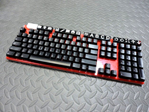
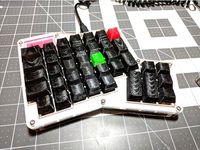
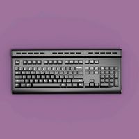
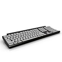
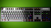
A 3D printable mechanical keyboard which includes 20 macro keys above the function key row and uses a Teensy 3.2 control board and ALPS key switches.
The Keycaps I made for this keyboard can be found here.
Bill of Materials:
Pack of 200 Matias ALPS Keyswiches ~ $50 USD
I chose the Quiet Click switches and love them
Matias ALPS Keycaps ~ $50 USD
Matias Keycap stabilizers ~ $10 USD
2x Pack of 100 1N4148 Low Signal Diodes ~ $11 CAD
Wire - Thin wire will be easier to work with. It's a 5v low current circuit so heavy gauge wire is not required.
Screws (18 total) - I used some spare #4-40 machine screws. Any screw about 9 mm long and 2.8 mm thread diameter should work
Teensy 3.2 ~ $27 CAD
If you choose to use another board keep in mind the following:
Other control boards will not be covered in these instructions
Your board of choice must have enough digital pins to wire the entire grid (28 pins) with additional pins required for LEDs
Required Tools:
3D Printer (obviously)
Soldering Iron and Solder
Electronics Side Cutters
Sharp Knife and/or Wire Strippers
Screw Driver (type depends on screws used)
Glue (I highly recommend slow cure two part epoxy with 45 min or longer working time
Recommended Tools/Supplies:
Measuring Calipers
Waxed paper
Paper Towels
Sand Paper
Stick On Rubber Feet
A Linux OS (for building controller firmware)
Not necessary but is easier to set up the required software than on a Windows or Mac computer
I used a Raspberry Pi 3 with Raspbian without any problems
Before You Begin:
This is a complicated build with about 450 solder joints and will require time, patience, and skill to complete. You will need to be or become proficient at soldering, altering and compiling source code, and uploading compiled code to the Teensy microcontroller. Having basic electronics knowledge will be helpful but is not required. I will not give complete instructions here, but rather give general build direction and advise, as well as offer links to a few resources which should give you all you need to know to complete this project. Make sure to read everything here as well as any information in the links provided. My explanations may not paint a very clear picture, so I have provided photos where I think they will help the most. Study them carefully. Good luck with your build and If you find yourself lost, ask a question here and I'll try to answer as best I can.
I have my 20 macro keys set up to send key combinations with a single key stroke (ctrl + alt + shift + a, or ctrl + alt + shift + b, or ctrl + alt + shift + c, etc), but you can set up the firmware to send a single key, combination of keys, or string of characters and combinations. Key combinations can be used to activate shortcuts or AutoHotkey scripts in windows or run scripts in Linux or Mac. I write C++ executables and have them run via shortcuts activated by key combinations.
As of this writing, I do not have functioning LEDs for Caps Lock, Num Lock, and Scroll Lock, which seems to bee a limitation of the kiibohd firmware. I haven't as of yet tried to figure out a solution.
Instructions:
Print the two small test pieces and check the fit of the keyswitches and the keycap supports. This will determine if you need to calibrate your printer and/or adjust any of the dimensions keyboard frame files. Alter the dimensions of the test pieces as necessary until correct fit has been achieved and use those dimensions to alter the keyboard frame files.
Print the two upper frame pieces and 3 lower frame pieces and remove any adhesion material. Test fit the two halves together and use a measuring caliper to check the space between the keyswitch openings across the joint. The measurement should be the same as the space between any other two keyswitchs (about 3.5 mm). Sand and scuff the joining faces of the two upper frame halves until the desired keyswitch gap is attained.
Test fit the Teensy control board in the middle lower frame piece. The reset button should line up with the hole in the bottom of the frame, and the corners of the board should fit loosely in the recessed support pieces in the lower frame. Use a sharp knife to alter the fit as necessary or alter the design and reprint the part to achieve the desired fit. Keep in mind that with the Teensy in the lower frame, and the lower and upper frames attached together, there should be a 2 mm gap between the Teensy and the upper frame. This is to allow for a 2mm thick piece of craft foam or other insulating material to be placed between the Teensy and the wires and switch pins that will be directly above it.
Place a sheet of waxed paper on a hard, flat surface such as a table top or workbench top. Apply glue to the joining faces of the upper frame halves and slide them together, wiping away any excess glue squeezed from the joint. Lay the frame on the waxed paper with another sheet of waxed paper on top and lay some heavy books on top too keep the frame flat while the glue cures.
Once the glue is fully cured, test fit the 3 lower frame pieces and compare the overall width of the lower frame to the width of the upper frame. The lower frame width must be equal or slightly less than the upper frame to ensure that the completed keyboard will not be warped when assembled. Test Installing the 18 screws now will help discover any warping. Sand and Scuff the joints of the 3 lower frame pieces until the desired fit is achieved.
Lay the upper frame upside down (screw holes facing upward) on a hard flat surface and lay a sheet of waxed paper on top. Apply glue to the joining faces of the 3 lower frame pieces and slide the pieces together wiping away any excess glue squeezed from the joint. Place the Lower frame on top of the waxed paper and and screw the lower frame to the upper, with the waxed paper sandwiched between. This will require some time to complete, so I recommend using a two part epoxy with at least 45 min working time. Lay another sheet of waxed paper on top of the lower frame and lay some heavy books on top the keep the assembly flat while the glue cures.
With the glue cured, remove the screws and discard the waxed paper. Use a sharp knife and/or sand paper to remove any excess glue that seeped from the joints. At this point you can install the keyswitch supports and keyswitches. I recommend waiting until everything is wired up before installing the keycaps as they may become scuffed or damaged while wiring the switches and control board.
Now it's time to get the soldering iron warmed up. You will be spending a few hours soldering, so also get a fume extractor running and work in a well ventilated area. Orient the upper frame so that the pins of the keyswitches are pointing to the sky and the spacebar switch is closest to you. The design the upper frame allows for the right pins of the keyswitches to be connected with a single wire making the columns, and the left pin of each switch will receive a diode, connecting each making the rows. Bend, cut and solder the leads of a few diodes so the anode (+) lead solders to the left pin of the keyswitch, and the cathode (-) lead is soldered to the cathode of the next diode in the row.Continue soldering the diodes until each switch has a diode and every switch is connected in a row. Next, take a single wire and cut it so that it will reach from the right pin of the top switch (macro row) to the right pin of the bottom row (spacebar row) connecting all of the right pins between to for a column. Strip the ends and mark and cut out a section of insulation for each switch in that column, then solder the wire in place. Repeat this for each column of the keyboard.
Next You'll need to solder the Teensy 3.2 to the columns and rows, completing the switch matrix. Some reading and planning will be helpful here. You'll need to run a wire from the end of each column and each row to a digital pin on the Teensy. 28 in total. Check out Dave Cooper's Keyboard Build and then have a look at the kiibohd/controller page to get a good handle on how to wire the control board in place. The gist of it is this; you can use any digital pin from 0 to 33 with the exception of pin 13 to connect to any row or column of the grid as you see fit, but write down which digital pin is used to connect to which row or column as you will need to know this when writing the firmware for the Teensy later.You'll also want to figure out weather or not you want to have LEDs for Caps Lock, Scroll Lock, and Num Lock. Because digital pins 28 to 33 will be inaccessible once everything is wired in place, having a well thought out plan now will make things much easier later. Keep in mind what I wrote in the "Before You Begin" section about LEDs; I haven't figured out how to get them working for Caps Lock, Scroll Lock, and Num Lock, but you can still connect some LED's now and figure out how to get them working later. To prevent burning out the LEDs, you'll also want a resistor in line with each LED.
Now that everything is wired up, place a piece of craft foam or other insulating material between the Teensy and the upper frame to prevent short circuits from occurring. You can use some double sided adhesive or glue to hold the foam in place
Time to start working on the firmware. If you haven't already checked out the kiibohd/controller page, you should head over there now and get your computer ready to build the firmware. I have to admit, there was steep learning curve for me at this point, but everything you need to know is on the kiibohd page, or linked from it. Have patience and understand that it may take some time to get everything figured out.
I think the two most annoying things I had to figure out were defining the digital pin matrix in the matrix.h file, and working out what the addresses of each switch is, and and how to map each letter/number/symbol/function to the addresses. I have provided a copy of my firmware source files for you to look at as examples. Unless you wired your control board exactly as I have (really unlikely), then don't use my matrix.h file in your firmware. You will still need to work out which pins were used in what order and for which column or row. Also, the key addresses in my scancode_map.kll file will not necessarily match your keyboard either, so you shouldn't use that in your firmware. The files are only provided as examples.
With the firmware installed and everything tested and working, if you haven't already done so, you can attach the lower frame with screws and place a few rubber feet on the bottom.
Similar models
thingiverse
free

4x4 Macro Keyboard by mattoyo
...ents:
3rd party arduino pro micro x 1
cherry mx style switches x 16
diodes x 16
m3 screws x 4
wires
double sided tape
patience...
3dwarehouse
free

Key switch (Cherry)
...small signal diode, and pcb pins hidden by default; unhide in the outliner if desired.) #cherry #key #keyboard #keyswitch #switch
thingiverse
free

Clueboard 660 66% Mechanical Keyboard by fumbucker
...m3 bolt and nut
6 * 20mm m3 bolt and nut (although 16mm should be ok for these too)
wire and solder
sticky rubber feet (optional)
3dwarehouse
free
Key switch (ALPS)
...key switch (alps)
3dwarehouse
exterior model of an alps mechanical keyboard switch. #alps #key #keyboard #keyswitch #switch
thingiverse
free

Clueboard / FC660m 66% Mechanical Keyboard v2 by fumbucker
...specifically for this keyboard with via support. it's wired similary to clueboard...
thingiverse
free
Mini 10keys Keyboard by gmanzato
...rmware. for now i've just implemented a basic numkey keyboard
pinout for the teensy :
row : f5, f6, f7, b6
cols : f0, f1, f4
thingiverse
free

Project Keyboard by BeNsAeI
...ype)
code (with error prone capslock): https://pastebin.com/lznfpy1c
code (with accurate capslock): https://pastebin.com/lag0njtp
thingiverse
free

Tenkeyless Keyboard - Plate Mount - Hand Wired
...r, because they interfered with the pins. instead, i just used double-sided tape. this part of the design could use refinement.
thingiverse
free
Switch-Diode soldering station by Mangolicious
...he leg of the diode around a 1mm drill (0,04"), put in the switch (from the underside), put the diode in the pin and solder.
grabcad
free

MECHANICAL KEYBOARD - 68 KEY - 65%
...e wire and maybe some rubber feet for the bottom
3d printing settings
material: pla
infill: 20%
layer height: .2mm
supports: no
Reallybigteeth
thingiverse
free

ALPS Macro Keycaps by ReallyBigTeeth
...y reallybigteeth
thingiverse
if you like what you see here, consider leaving a tip.
custome made alps keycaps for macro keyboard
thingiverse
free
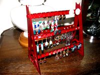
Earring/Jewellery Stand by ReallyBigTeeth
...he print bed. clip together to assemble. use a dab of glue if you wish.
thanks goes out to kyllikki for physical connections.
thingiverse
free
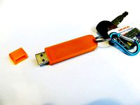
Corsair Voyager GT USB Case for Keyring by ReallyBigTeeth
...e what you see here, consider leaving a tip.
case for a corsair voyager gt usb stick that has a hole for attaching to a key ring.
thingiverse
free
Ergodox ALPS DCS Keycap set by ReallyBigTeeth
...eyboards with alps switches.
print right side up with support. sand the top surface for a more comfortable typing experience.
thingiverse
free
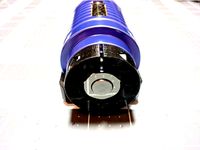
REVOMAZE Puzzle Grip by ReallyBigTeeth
...icator on the puzzle's core and tighten the screw.
the revomaze stand can be found here.
check out the revomaze website here.
thingiverse
free
Nexus 7 (2013) Laser Barcode Scanner (Symbol LS3408) by ReallyBigTeeth
...erse
if you like what you see here, consider leaving a tip.
combine a nexus 7 (2013) with a symbol ls3408 laser barcode scanner.
thingiverse
free
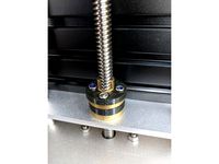
T8 Leadscrew Anti-Backlash Spacer by ReallyBigTeeth
.... the assembly is fastend together using m3 bolts. the model may need adjustment to get the correct thickness for your assembly.
thingiverse
free
REVOMAZE Stand - Remix by ReallyBigTeeth
...viewtopic.php?f=25&t=2430&p=55627#p55627
the revomaze puzzle grip can be found here.
check out the revomaze website here.
thingiverse
free
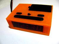
Digital Clock Case (Cardinal Model 6025 / 928) by ReallyBigTeeth
...al clock enclosure for cardinal alarm clock model 6025. basic model 928. uses battery door and buttons from original clock case.
thingiverse
free
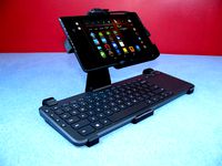
Nexus 7 2013 Keyboard stand by ReallyBigTeeth
....
use a keyboard with your tablet while laying in bed, sitting in a chair, or at a desk.
assembly viideo
angle adjustment video
Alps
turbosquid
$15

Alpes Inox Oven
... available on turbo squid, the world's leading provider of digital 3d models for visualization, films, television, and games.
3d_export
free
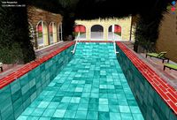
provence-alpes-cote-dazur-france
...-alpes-cote-dazur-france
3dexport
the indoor swimming pool is inspired by the swimming pool at provence-alpes-cote-dazur-france.
turbosquid
$12

Alpes Inox Kitchen Sink
... available on turbo squid, the world's leading provider of digital 3d models for visualization, films, television, and games.
turbosquid
$21

House Chalet Alps - Modern Cottage
... 3d model house chalet alps for download as skp, obj, and dae on turbosquid: 3d models for games, architecture, videos. (1684344)
turbosquid
$15

Alpes Inox Kitchen Furniture and Appliances
... available on turbo squid, the world's leading provider of digital 3d models for visualization, films, television, and games.
turbosquid
$6

Aluminum Profile for Led (ALP-023)
... available on turbo squid, the world's leading provider of digital 3d models for visualization, films, television, and games.
3ddd
free
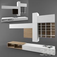
ALPE ARREDAMENTI SRL IRIDE PROPOSTA 1
...
высота - 2200mm
длина - 3000mm
глубина - 580mm
объем в упаковке: 4.60м3http://www.mebit.ru/catalog/walls/view-688.html
turbosquid
$79
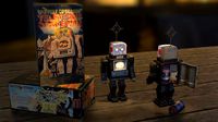
ALPS Japan Televison Spaceman retro tin toy
... available on turbo squid, the world's leading provider of digital 3d models for visualization, films, television, and games.
humster3d
$75

3D model of Hino 258 ALP Tow Truck 2007
... 3d model of hino 258 alp tow truck 2007 in various file formats. all our 3d models were created maximally close to the original.
3ddd
$1
La Fabbrica THRILL FROST, ALPS
... 2014, 2013, 2011,
obj
_____________________________________http://www.lafabbrica.it/ru/collections/thrill-12#slider-10
Macro
turbosquid
$40

Macro Watersplash
...
royalty free 3d model macro watersplash for download as obj on turbosquid: 3d models for games, architecture, videos. (1573250)
turbosquid
free

Geode macro
... available on turbo squid, the world's leading provider of digital 3d models for visualization, films, television, and games.
turbosquid
$9

Macro MCR black coin
...oyalty free 3d model macro mcr black coin for download as max on turbosquid: 3d models for games, architecture, videos. (1614233)
turbosquid
$9

Macro MCR gold coin
...royalty free 3d model macro mcr gold coin for download as max on turbosquid: 3d models for games, architecture, videos. (1614229)
3d_export
$59
Sony HVL-RL1 Macro Ring Light 3D Model
... ring flash shot hvlf43am external light photo camera photography
sony hvl-rl1 macro ring light 3d model humster3d 98111 3dexport
cg_studio
$59

Sony HVL-RL1 Macro Ring Light3d model
...mb .lwo .fbx .c4d .3ds - sony hvl-rl1 macro ring light 3d model, royalty free license available, instant download after purchase.
turbosquid
$60

MACRO LENS 58 MM 2.0X MAG 2016
... available on turbo squid, the world's leading provider of digital 3d models for visualization, films, television, and games.
turbosquid
$50

MACRO LENS 58 MM 2.0X 2016 RAW
... available on turbo squid, the world's leading provider of digital 3d models for visualization, films, television, and games.
3d_export
$59
Sony HVL-MT24AM Macro Twin Flash Kit 3D Model
...43am external light photo camera photography in real units
sony hvl-mt24am macro twin flash kit 3d model humster3d 97489 3dexport
humster3d
$50
3D model of Sony HVL-RL1 Macro Ring Light
...d model of sony hvl-rl1 macro ring light in various file formats. all our 3d models were created maximally close to the original.
Keyboard
3d_ocean
$9
Keyboard
...odels computer electronics keyboard peripheral / part
computer keyboard 3d models. it’s computer keyboard. render ready keyboard.
archibase_planet
free
Keyboard
...keyboard
archibase planet
input keyboard keyboard office equipment
pro keyboard - 3d model for interior 3d visualization
3d_export
$5
keyboard
...keyboard
3dexport
computer keyboard
3d_export
$11
Keyboard
...keyboard
3dexport
gaming keyboard with backlight 1:1
3d_export
free
keyboard
...keyboard
3dexport
keyboard blender stl obj fbx
archibase_planet
free
Keyboard
...keyboard
archibase planet
keyboard pc equipment
keyboard apple n130315 - 3d model (*.gsm+*.3ds) for interior 3d visualization.
3d_export
free
keyboard gaming
...keyboard gaming
3dexport
keyboard gaming include: 1 x keyboard gaming.blend 3 x keyboard gaming.png
archibase_planet
free
Keyboard
...keyboard
archibase planet
keyboar pc equipment
keyboard - 3d model (*.gsm+*.3ds) for interior 3d visualization.
3d_ocean
$9

keyboard USB
...models computer electronics keyboard peripheral / part
keyboard for computer 3d models. high detailed model of computer keyboard.
turbosquid
$24

Keyboard
...urbosquid
royalty free 3d model keyboard for download as max on turbosquid: 3d models for games, architecture, videos. (1710291)
Keys
archibase_planet
free
Key
...key archibase planet bunch of keys key key n190510 - 3d model (*.gsm+*.3ds) for interior...
3d_export
$5
key
...key
3dexport
key
archibase_planet
free
Key
...key
archibase planet
key
key n080710 - 3d model (*.3ds) for interior 3d visualization.
3d_ocean
$2
Key
...key
3docean
door key lock open unlock
a key facecount: 617 (2x subsurfed: 9872)
archibase_planet
free
Key
...key
archibase planet
key
key n240713 - 3d model (*.gsm+*.3ds) for interior 3d visualization.
archibase_planet
free
Key
...key
archibase planet
key
key 2 n080710 - 3d model (*.gsm+*.3ds) for interior 3d visualization.
turbosquid
$3
Keys With Key Chain
... chain 3d model for download as blend, dae, stl, obj, and fbx on turbosquid: 3d models for games, architecture, videos. (1673644)
archibase_planet
free
Key
...key
archibase planet
key
key ancient strike plate n130912 - 3d model (*.3ds) for interior 3d visualization.
archibase_planet
free
Key
...key
archibase planet
key
key stephan mette n300412 - 3d model (*.gsm+*.3ds) for interior 3d visualization.
3d_export
free
key
...key
3dexport
a simple key obj, fbx, blend
Mechanical
3d_export
$50

Mechanism
...mechanism
3dexport
mechanism -------- animation is present only in the blender file.
3d_export
$5

mechanics
...mechanics
3dexport
turbosquid
$50
mechanic
... available on turbo squid, the world's leading provider of digital 3d models for visualization, films, television, and games.
3ddd
$1
Mechanical Wasp
...mechanical wasp
3ddd
робот
mechanical wasp
3d_export
$20
Mechanical tail
...mechanical tail
3dexport
mechanical tail<br>four-part movement
3d_export
$5
mechanical ballista
...mechanical ballista
3dexport
a mechanical ballista useful for medieval or fantasy games does not contain animations
turbosquid
$59
Mechanical Part
...id
royalty free 3d model mechanical part for download as c4d on turbosquid: 3d models for games, architecture, videos. (1410833)
turbosquid
$50
Mechanical Spider
...royalty free 3d model mechanical spider for download as blend on turbosquid: 3d models for games, architecture, videos. (1599864)
turbosquid
$45

Mechanical Pencil
...royalty free 3d model mechanical pencil for download as blend on turbosquid: 3d models for games, architecture, videos. (1503379)
turbosquid
$35

Mechanical fish
...id
royalty free 3d model mechanical fish for download as max on turbosquid: 3d models for games, architecture, videos. (1152530)
20
3d_export
$15
rocks 20
...rocks 20
3dexport
rocks 3d model 20
3ddd
$1

DECOR MEDIEVO 20*20 MIX
...ллекция: bolonia
фабрика: mainzu
страна: испания
размер: 20x20 см
ссылка:http://www.mainzu.com/bolonia.php#prettyphoto
3d_export
$6
tap-20
...tap-20
3dexport
3ddd
$1

Bed 20
...bed 20
3ddd
постельное белье
bed 20. i hope you like it
software : 3dsmax + md + vray 2.4
turbosquid
$40

20 Shields
...turbosquid
royalty free 3d model 20 shields for download as on turbosquid: 3d models for games, architecture, videos. (1305068)
3d_export
$5

houseberg home 20
...houseberg home 20
3dexport
houseberg home 20
turbosquid
$96

J-20
...20
turbosquid
royalty free 3d model j-20 for download as max on turbosquid: 3d models for games, architecture, videos. (1658873)
turbosquid
$10

Decor 20
...urbosquid
royalty free 3d model decor 20 for download as stl on turbosquid: 3d models for games, architecture, videos. (1677149)
turbosquid
$10

building 20
...osquid
royalty free 3d model building 20 for download as max on turbosquid: 3d models for games, architecture, videos. (1362227)
turbosquid
$6
Bedcloth 20
...osquid
royalty free 3d model bedcloth 20 for download as max on turbosquid: 3d models for games, architecture, videos. (1522681)