Thingiverse

Marlin 1.1.x or 2.x on Anet A8 Guide by morganlowe
by Thingiverse
Last crawled date: 4 years ago
So I wanted to write about my journey from stock Anet A8 to Skynet then finally to Marlin. In my things you will see bits of code posted for setting up the print heads for the printer. This guide is more about converting from one firmware to another. This applies to RAMPS converted units only. I have not tried Marlin on a stock Anet A8 board, for that I use Skynet3d from https://github.com/thijsk/Skynet3d
Marlin 2.0 is now live!
I have updated to Marlin 2.0. Autolevel works better and that's all I have noticed! I do run RAMPS. The instructions are still the same, you mess with the configuration.h and thats it. Same files are there and with 8bit boards you still use the Arduino IDE. I will make a guide for 32bit boards when I get to it.
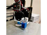
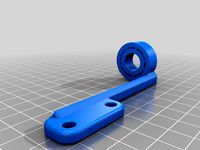
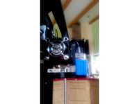
I have included the files for the 18mm Sensor Carriage with chain from https://www.thingiverse.com/thing:2766701
See the RAMPS tutorial here!
See the Octoprint and GPIO tutorial here!
Marlin can be found at http://marlinfw.org See that site for detailed instructions, information and guides.
OK on to the guide!
This is to achieve 3 goals for me:
A universal firmware with large community support
Advanced features and controls
Future proofing and improvements to come
For me Marlin meets these goals. I already posted a link to the firmware page but you will also need a few more things.
Arduino IDE on your computer from https://www.arduino.cc/en/Main/Software
I like to use Notepadd++ for quick edits https://notepad-plus-plus.org/
a USB cable to attach your Arduino to your PC
RAMPS 1.4 or 1.5 board http://reprap.org/wiki/RAMPS_1.4
Arduino MEGA 2560 or clone https://www.arduino.cc/en/Main/ArduinoBoardMega2560?setlang=en
Once you have these things and have wired your printer up to the RAMPS board you need some firmware to control things. First step is to download Marlin from the website above. Extract the folder and install the Arduino IDE.
Inside the downloaded folder for Marlin you will find \Marlin-1.1.x\Marlin\example_configurations\Anet\A8. In that folder is two files Configuration.h and Configuration_adv.h. Copy these files into \Marlin-1.1.x\Marlin replacing what is there. This is the basic configuration for the Anet A8 and gets you started.
Now if you really want to download this thing in inside is my Configuration.h for my Anet A8 with my carriage from https://www.thingiverse.com/thing:2766701 and an 18mm inductive sensor with bilinear bed leveling. Just like above copy these files into \Marlin-1.1.x\Marlin overwrite what`s there. Then you can just tweak them to meet your needs. This might be the easiest route.
Open the Arduino IDE and browse to your downloaded Marlin files. Inside \Marlin-1.1.x\Marlin you will find Marlin.INO. This is the file you need to load into the Arduino IDE.
Inside the Arduino IDE you will see tabs across the top. Select the tab "Configuration.h" and start reading. There`s lots of comments to help you setup and understand what each line does but there are a few we will need to concentrate on.
The sample configurations assume a bone stock Anet A8 with stock carriage and all. You can just run with those if that is what you have.
First thing to change is the serial baudrate. This is set with the line #define BAUDRATE 115200 This is the stock setting for an Anet A8 and works just fine. If you encounter issues with dropped communication when printing consider slowing it down a little. #define BAUDRATE 57600 is the next slowest for example.
Next thing to set is your motherboard. In the tab "Boards.h" you will find a list of the boards and their codes. I use #define MOTHERBOARD BOARD_RAMPS_14_EEB because I have RAMPS 1.5 with Extruder, Extruder, Build plate heater connections. These corospond to the screw terminals marked D10, D9, D8 on the RAMPS board. So what we have set here is:
RAMPS Motherboard
D10 is extruder 0
D9 is extruder 1
D8 is heated bed
Now with this setting the firmware automatically moves the cooling fan PWM output to the SERVO section on the RAMPS board. The set of 3 servo pins furthest from the RAMPS power connector are what is used but be aware these pins are not meant to handle power. You will need to use a MOSFET between them and 12v to power the fans. I found inexpensive Arduino compatable MOSFETs on Amazon for a few dollars.
This must be set to #define MOTHERBOARD BOARD_RAMPS_14_EFB if you have a single extruder. This assigns the outputs to:
RAMPS Motherboard
D10 is extruder 0
D9 is cooling fans
D8 is heated bed
Next comes the #define CUSTOM_MACHINE_NAME "Your Name Here" line. This is just the name reported over serial and displayed in the printer ready message on the LCD screen. It can be set to about anything.
The next line sets the number of extruders. This goes with the motherboard setting above. #define EXTRUDERS 2 if you have 2, #define EXTRUDERS 1 for one, so on.
Next is the setting for filiment size. This is how the machine calculates how much to feed. Set it to 1.75 if that is what you are using, it is pretty much the standard though there are other sizes. #define DEFAULT_NOMINAL_FILAMENT_DIA 1.75 for 1.75.
A little further down is the next one to look at. If you have more than one extruder you need to remove the //s in front of both lines and set your offset. If single extruder leave this commented out.#define HOTEND_OFFSET_X {0.0, 35.00}and#define HOTEND_OFFSET_Y {0.0, 0.00}` is the setting for my dual extruder heads for example.
Theres a large block of text talking about thermal sensors. We might need to change this especially if you have dual extuders.#define TEMP_SENSOR_0 5` is for extruder 0 for example and tells the firmware you have a 100K thermistor type sensor. This is the most common type. I have the settings below set for my dual extruder carriage.
#define TEMP_SENSOR_0 5#define TEMP_SENSOR_1 5#define TEMP_SENSOR_2 - 4 are set to 0#define TEMP_SENSOR_BED 5
I do not mess with the PID and thermal runaway settings. They seem fine.
Next section is endstop inverting. These all should be set to true.#define X_MIN_ENDSTOP_INVERTING true#define Y_MIN_ENDSTOP_INVERTING true#define Z_MIN_ENDSTOP_INVERTING true#define X_MAX_ENDSTOP_INVERTING true#define Y_MAX_ENDSTOP_INVERTING true#define Z_MAX_ENDSTOP_INVERTING true#define Z_MIN_PROBE_ENDSTOP_INVERTING true
Next we have Distict E Factors. This lets you setup your dual extruders with differnt feed speeds. Uncomment the line #define DISTINCT_E_FACTORS to enable this if needed. I run two identical extruders so I left it commented out.
Following is the default axis steps per unit. The unit here is MM. This is an initial setting. I use LV8729 drivers on 1/32 microstepping. This means the following must be set here.
#define DEFAULT_AXIS_STEPS_PER_UNIT {200, 200, 800, 200}
If you are using 1/16th stepping you would set:
#define DEFAULT_AXIS_STEPS_PER_UNIT {100, 100, 400, 100}
Skipping ahead we come to the Z Probe Options. This is where you setup the probe for auto level.
The line #define Z_MIN_PROBE_USES_Z_MIN_ENDSTOP_PIN means the probe is connected to the same pins as the min Z switch was.
You can comment that line out and set the line below it #define Z_MIN_PROBE_ENDSTOP xx where XX is the Arduino pin number for where the probe signal goes.
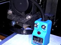
Probe type is reffering to the mounting. All my heads use a fixed probe so set#define FIX_MOUNTED_PROBE
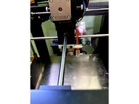
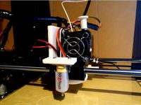
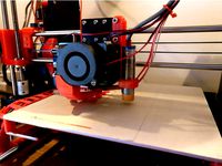
Down from there is the settings for the offsets. Using my Front Sensor Carriage from https://www.thingiverse.com/thing:2766701 you would set:
#define X_PROBE_OFFSET_FROM_EXTRUDER 17#define Y_PROBE_OFFSET_FROM_EXTRUDER -23#define Z_PROBE_OFFSET_FROM_EXTRUDER -2.1
The last line is the difference in height between the extruder nozzle and the probe trigger point. We will come back to that.
I like to uncomment and turn on #define MULTIPLE_PROBING 2 to set it to probe each point twice. This is to make sure that it has an accurate reading.
Next few lines to tweak are the Z clearances. This is what tells the machine to lift up between probe points. I like to turn this on so I always clears.
#define Z_CLEARANCE_DEPLOY_PROBE 10 // Z Clearance for Deploy/Stow#define Z_CLEARANCE_BETWEEN_PROBES 5 // Z Clearance between probe points
This means it will lift 10mm from the bed when it starts and stops probing and between each point it will lift 5mm before moving.
Down from there is the machine settings and motor inverting settings. This depends on how you wired it and the motor drives used. Mine is all backwards so I had to change these settings to what you see below. Keep in mind you might not have to.
#define INVERT_X_DIR true#define INVERT_Y_DIR true#define INVERT_Z_DIR false#define INVERT_E0_DIR false#define INVERT_E1_DIR true
The reason one is inverted and the other not is because of how I mounted them. Again this setting depends on many things and should be checked by carefully moving the printer once the firmware is flashed.
Down from there is the settings for the bed size.#define X_BED_SIZE 220#define Y_BED_SIZE 220
Then the travel limits. These are also known as Home Offsets and can be changed via terminal later. For my Carriage its:
#define X_MAX_POS 240#define X_MIN_POS -10#define Y_MAX_POS 225#define Y_MIN_POS -13#define Z_MAX_POS 230#define Z_MIN_POS 0
These are also used for the software endstops.
Next we come to the Bed Leveling section. This is where you choose how and where to probe. I like to use Bilinear for it gives excellent results and is easy to run. You must add G29 to the start Gcode of your prints after it homes.
Uncomment the line #define AUTO_BED_LEVELING_BILINEAR to enable or choose what you think will be best for you.
You can choose how many points it probes with the settings#define GRID_MAX_POINTS_X 4#define GRID_MAX_POINTS_Y GRID_MAX_POINTS_X
This gives 4x4 or 16 probe points. Less is faster more is more precise. More than 7 though can cause performance and memory issues.
Once you choose one you must set where the probe can reach. For my front probe carriages on an Anet A8 it`s
#define LEFT_PROBE_BED_POSITION 30#define RIGHT_PROBE_BED_POSITION 200#define BACK_PROBE_BED_POSITION 190#define FRONT_PROBE_BED_POSITION 20
As a part of this check and be sure that #define Z_SAFE_HOMING is enabled and not commented out. By default in the Marlin config for the Anet A8 it should be enabled.
Moving on to the Additional Settings section we come to Preheat Constants. Set your Preheat settings here. I like to run 50c on the bed and 200c on the extruders. It you have more than one extruder you must have more than one setting here like below.
Extruder 0:#define PREHEAT_1_TEMP_HOTEND 200#define PREHEAT_1_TEMP_BED 50#define PREHEAT_1_FAN_SPEED 0 // Value from 0 to 255
Extruder 1:#define PREHEAT_2_TEMP_HOTEND 200#define PREHEAT_2_TEMP_BED 50#define PREHEAT_2_FAN_SPEED 0 // Value from 0 to 255
Now to LCD and SD support. This is where you setup your LCD controller. I like to use the RAMPS compatible RepRapDiscount FULL GRAPHIC Smart Controller. This is also known as the 12864 LCD. A common issue with these is the knob goes the wrong direction. You change it with the line #define REVERSE_ENCODER_DIRECTION by uncommenting it.
From the list below that line uncomment the one that matches your controller. Using the same example that is #define REPRAP_DISCOUNT_FULL_GRAPHIC_SMART_CONTROLLER
That should be enough to get you going!
Now to compile. From the TOOLS menu in the Arduino IDE select your board. In this case it`s "Arduino/Genduino MEGA or MEGA 2560". Then select your COM port the board is connected to.
Click on the checkmark button at the top of the screen and the program will compile. This will take a few minutes and if there`s any issues it will tell you what they are in orange print in the black bar at the bottom of the screen. If all is well it will say "Done Compiling" and give you a summary of the memory usage.
With it compiled its time to upload. Hit the -> right arrow looking icon at the top with your board plugged in to USB and it will compile then upload. Once again you will get "Upload Complete" should it all work out fine and now its programmed.
From here you need to verify everything is moving in the right directions. Move your axis slowly to be sure. Once all tests pass try warming it up. Make sure the temperature probes are reporting right and everything else is working.
Assuming you use a probe to do Autoleveling you will need to set the Z offset. Here`s the easy route I found.
Home all axis with G28
Set the offset to 0 to start with M851 Z0 then send M500 and load with M501
Move to the middle of the bed with G1 X110 Y110
Turn off software endstops. This means your machine could potentially crash into the bed so be careful, M211 S0
Place a bit of paper on the bed under the nozzle and preheat the machine. Bring it up to operating temperature and be careful! Don`t get burned.
Lower the Z slowly until that bit of paper is lightly pinched between the bed and nozzle.
Send command M114 to get the current position. You will see something like Recv: X:110.00 Y:110.00 Z:2.10 E:0.00 Count X:26000 Y:22000 Z:1680
From that line take the Z position and add a - to the front for Z-2.1 in this example
Set the offset with M851 Z-2.1 be sure to use your offset!
BE SURE TO ENABLE SOFTWARE ENDSTOPS with M211 S1
Save the setting with M500
You can run a quick autolevel with G29 to make sure it all works.
In your slicer be sure to add the line G29 ;Autolevel to the start gcode under the line with G28 in it. This levels the printer at the start of each print. Great if your machines moves around like mine. I take it place to place.
That should be it, you now have auto leveling Marlin powered Anet A8. There`s a lot I glossed over but you can learn more from these links where I sourced this guide from.
http://marlinfw.org/
https://3dprint.wiki/reprap/anet/a8/improvement/autobedleveling
http://marlinfw.org/docs/gcode/M851.html
http://marlinfw.org/docs/gcode/M206.html
http://marlinfw.org/docs/gcode/M092.html
http://marlinfw.org/docs/gcode/M218.html
http://marlinfw.org/docs/gcode/M114.html
https://github.com/MarlinFirmware/Marlin/wiki/EEPROM
https://www.arduino.cc/
http://reprap.org/wiki/RAMPS_1.4
http://www.reprap.org/mediawiki/images/0/06/RAMPS_dossier.pdf
http://www.reprap.org/
And of course the Thingiverse community!
Thank you! Like, share it with those who can benefit, yell at me in the comments if I got it wrong and enjoy!
Marlin 2.0 is now live!
I have updated to Marlin 2.0. Autolevel works better and that's all I have noticed! I do run RAMPS. The instructions are still the same, you mess with the configuration.h and thats it. Same files are there and with 8bit boards you still use the Arduino IDE. I will make a guide for 32bit boards when I get to it.
I have included the files for the 18mm Sensor Carriage with chain from https://www.thingiverse.com/thing:2766701
See the RAMPS tutorial here!
See the Octoprint and GPIO tutorial here!
Marlin can be found at http://marlinfw.org See that site for detailed instructions, information and guides.
OK on to the guide!
This is to achieve 3 goals for me:
A universal firmware with large community support
Advanced features and controls
Future proofing and improvements to come
For me Marlin meets these goals. I already posted a link to the firmware page but you will also need a few more things.
Arduino IDE on your computer from https://www.arduino.cc/en/Main/Software
I like to use Notepadd++ for quick edits https://notepad-plus-plus.org/
a USB cable to attach your Arduino to your PC
RAMPS 1.4 or 1.5 board http://reprap.org/wiki/RAMPS_1.4
Arduino MEGA 2560 or clone https://www.arduino.cc/en/Main/ArduinoBoardMega2560?setlang=en
Once you have these things and have wired your printer up to the RAMPS board you need some firmware to control things. First step is to download Marlin from the website above. Extract the folder and install the Arduino IDE.
Inside the downloaded folder for Marlin you will find \Marlin-1.1.x\Marlin\example_configurations\Anet\A8. In that folder is two files Configuration.h and Configuration_adv.h. Copy these files into \Marlin-1.1.x\Marlin replacing what is there. This is the basic configuration for the Anet A8 and gets you started.
Now if you really want to download this thing in inside is my Configuration.h for my Anet A8 with my carriage from https://www.thingiverse.com/thing:2766701 and an 18mm inductive sensor with bilinear bed leveling. Just like above copy these files into \Marlin-1.1.x\Marlin overwrite what`s there. Then you can just tweak them to meet your needs. This might be the easiest route.
Open the Arduino IDE and browse to your downloaded Marlin files. Inside \Marlin-1.1.x\Marlin you will find Marlin.INO. This is the file you need to load into the Arduino IDE.
Inside the Arduino IDE you will see tabs across the top. Select the tab "Configuration.h" and start reading. There`s lots of comments to help you setup and understand what each line does but there are a few we will need to concentrate on.
The sample configurations assume a bone stock Anet A8 with stock carriage and all. You can just run with those if that is what you have.
First thing to change is the serial baudrate. This is set with the line #define BAUDRATE 115200 This is the stock setting for an Anet A8 and works just fine. If you encounter issues with dropped communication when printing consider slowing it down a little. #define BAUDRATE 57600 is the next slowest for example.
Next thing to set is your motherboard. In the tab "Boards.h" you will find a list of the boards and their codes. I use #define MOTHERBOARD BOARD_RAMPS_14_EEB because I have RAMPS 1.5 with Extruder, Extruder, Build plate heater connections. These corospond to the screw terminals marked D10, D9, D8 on the RAMPS board. So what we have set here is:
RAMPS Motherboard
D10 is extruder 0
D9 is extruder 1
D8 is heated bed
Now with this setting the firmware automatically moves the cooling fan PWM output to the SERVO section on the RAMPS board. The set of 3 servo pins furthest from the RAMPS power connector are what is used but be aware these pins are not meant to handle power. You will need to use a MOSFET between them and 12v to power the fans. I found inexpensive Arduino compatable MOSFETs on Amazon for a few dollars.
This must be set to #define MOTHERBOARD BOARD_RAMPS_14_EFB if you have a single extruder. This assigns the outputs to:
RAMPS Motherboard
D10 is extruder 0
D9 is cooling fans
D8 is heated bed
Next comes the #define CUSTOM_MACHINE_NAME "Your Name Here" line. This is just the name reported over serial and displayed in the printer ready message on the LCD screen. It can be set to about anything.
The next line sets the number of extruders. This goes with the motherboard setting above. #define EXTRUDERS 2 if you have 2, #define EXTRUDERS 1 for one, so on.
Next is the setting for filiment size. This is how the machine calculates how much to feed. Set it to 1.75 if that is what you are using, it is pretty much the standard though there are other sizes. #define DEFAULT_NOMINAL_FILAMENT_DIA 1.75 for 1.75.
A little further down is the next one to look at. If you have more than one extruder you need to remove the //s in front of both lines and set your offset. If single extruder leave this commented out.#define HOTEND_OFFSET_X {0.0, 35.00}and#define HOTEND_OFFSET_Y {0.0, 0.00}` is the setting for my dual extruder heads for example.
Theres a large block of text talking about thermal sensors. We might need to change this especially if you have dual extuders.#define TEMP_SENSOR_0 5` is for extruder 0 for example and tells the firmware you have a 100K thermistor type sensor. This is the most common type. I have the settings below set for my dual extruder carriage.
#define TEMP_SENSOR_0 5#define TEMP_SENSOR_1 5#define TEMP_SENSOR_2 - 4 are set to 0#define TEMP_SENSOR_BED 5
I do not mess with the PID and thermal runaway settings. They seem fine.
Next section is endstop inverting. These all should be set to true.#define X_MIN_ENDSTOP_INVERTING true#define Y_MIN_ENDSTOP_INVERTING true#define Z_MIN_ENDSTOP_INVERTING true#define X_MAX_ENDSTOP_INVERTING true#define Y_MAX_ENDSTOP_INVERTING true#define Z_MAX_ENDSTOP_INVERTING true#define Z_MIN_PROBE_ENDSTOP_INVERTING true
Next we have Distict E Factors. This lets you setup your dual extruders with differnt feed speeds. Uncomment the line #define DISTINCT_E_FACTORS to enable this if needed. I run two identical extruders so I left it commented out.
Following is the default axis steps per unit. The unit here is MM. This is an initial setting. I use LV8729 drivers on 1/32 microstepping. This means the following must be set here.
#define DEFAULT_AXIS_STEPS_PER_UNIT {200, 200, 800, 200}
If you are using 1/16th stepping you would set:
#define DEFAULT_AXIS_STEPS_PER_UNIT {100, 100, 400, 100}
Skipping ahead we come to the Z Probe Options. This is where you setup the probe for auto level.
The line #define Z_MIN_PROBE_USES_Z_MIN_ENDSTOP_PIN means the probe is connected to the same pins as the min Z switch was.
You can comment that line out and set the line below it #define Z_MIN_PROBE_ENDSTOP xx where XX is the Arduino pin number for where the probe signal goes.
Probe type is reffering to the mounting. All my heads use a fixed probe so set#define FIX_MOUNTED_PROBE
Down from there is the settings for the offsets. Using my Front Sensor Carriage from https://www.thingiverse.com/thing:2766701 you would set:
#define X_PROBE_OFFSET_FROM_EXTRUDER 17#define Y_PROBE_OFFSET_FROM_EXTRUDER -23#define Z_PROBE_OFFSET_FROM_EXTRUDER -2.1
The last line is the difference in height between the extruder nozzle and the probe trigger point. We will come back to that.
I like to uncomment and turn on #define MULTIPLE_PROBING 2 to set it to probe each point twice. This is to make sure that it has an accurate reading.
Next few lines to tweak are the Z clearances. This is what tells the machine to lift up between probe points. I like to turn this on so I always clears.
#define Z_CLEARANCE_DEPLOY_PROBE 10 // Z Clearance for Deploy/Stow#define Z_CLEARANCE_BETWEEN_PROBES 5 // Z Clearance between probe points
This means it will lift 10mm from the bed when it starts and stops probing and between each point it will lift 5mm before moving.
Down from there is the machine settings and motor inverting settings. This depends on how you wired it and the motor drives used. Mine is all backwards so I had to change these settings to what you see below. Keep in mind you might not have to.
#define INVERT_X_DIR true#define INVERT_Y_DIR true#define INVERT_Z_DIR false#define INVERT_E0_DIR false#define INVERT_E1_DIR true
The reason one is inverted and the other not is because of how I mounted them. Again this setting depends on many things and should be checked by carefully moving the printer once the firmware is flashed.
Down from there is the settings for the bed size.#define X_BED_SIZE 220#define Y_BED_SIZE 220
Then the travel limits. These are also known as Home Offsets and can be changed via terminal later. For my Carriage its:
#define X_MAX_POS 240#define X_MIN_POS -10#define Y_MAX_POS 225#define Y_MIN_POS -13#define Z_MAX_POS 230#define Z_MIN_POS 0
These are also used for the software endstops.
Next we come to the Bed Leveling section. This is where you choose how and where to probe. I like to use Bilinear for it gives excellent results and is easy to run. You must add G29 to the start Gcode of your prints after it homes.
Uncomment the line #define AUTO_BED_LEVELING_BILINEAR to enable or choose what you think will be best for you.
You can choose how many points it probes with the settings#define GRID_MAX_POINTS_X 4#define GRID_MAX_POINTS_Y GRID_MAX_POINTS_X
This gives 4x4 or 16 probe points. Less is faster more is more precise. More than 7 though can cause performance and memory issues.
Once you choose one you must set where the probe can reach. For my front probe carriages on an Anet A8 it`s
#define LEFT_PROBE_BED_POSITION 30#define RIGHT_PROBE_BED_POSITION 200#define BACK_PROBE_BED_POSITION 190#define FRONT_PROBE_BED_POSITION 20
As a part of this check and be sure that #define Z_SAFE_HOMING is enabled and not commented out. By default in the Marlin config for the Anet A8 it should be enabled.
Moving on to the Additional Settings section we come to Preheat Constants. Set your Preheat settings here. I like to run 50c on the bed and 200c on the extruders. It you have more than one extruder you must have more than one setting here like below.
Extruder 0:#define PREHEAT_1_TEMP_HOTEND 200#define PREHEAT_1_TEMP_BED 50#define PREHEAT_1_FAN_SPEED 0 // Value from 0 to 255
Extruder 1:#define PREHEAT_2_TEMP_HOTEND 200#define PREHEAT_2_TEMP_BED 50#define PREHEAT_2_FAN_SPEED 0 // Value from 0 to 255
Now to LCD and SD support. This is where you setup your LCD controller. I like to use the RAMPS compatible RepRapDiscount FULL GRAPHIC Smart Controller. This is also known as the 12864 LCD. A common issue with these is the knob goes the wrong direction. You change it with the line #define REVERSE_ENCODER_DIRECTION by uncommenting it.
From the list below that line uncomment the one that matches your controller. Using the same example that is #define REPRAP_DISCOUNT_FULL_GRAPHIC_SMART_CONTROLLER
That should be enough to get you going!
Now to compile. From the TOOLS menu in the Arduino IDE select your board. In this case it`s "Arduino/Genduino MEGA or MEGA 2560". Then select your COM port the board is connected to.
Click on the checkmark button at the top of the screen and the program will compile. This will take a few minutes and if there`s any issues it will tell you what they are in orange print in the black bar at the bottom of the screen. If all is well it will say "Done Compiling" and give you a summary of the memory usage.
With it compiled its time to upload. Hit the -> right arrow looking icon at the top with your board plugged in to USB and it will compile then upload. Once again you will get "Upload Complete" should it all work out fine and now its programmed.
From here you need to verify everything is moving in the right directions. Move your axis slowly to be sure. Once all tests pass try warming it up. Make sure the temperature probes are reporting right and everything else is working.
Assuming you use a probe to do Autoleveling you will need to set the Z offset. Here`s the easy route I found.
Home all axis with G28
Set the offset to 0 to start with M851 Z0 then send M500 and load with M501
Move to the middle of the bed with G1 X110 Y110
Turn off software endstops. This means your machine could potentially crash into the bed so be careful, M211 S0
Place a bit of paper on the bed under the nozzle and preheat the machine. Bring it up to operating temperature and be careful! Don`t get burned.
Lower the Z slowly until that bit of paper is lightly pinched between the bed and nozzle.
Send command M114 to get the current position. You will see something like Recv: X:110.00 Y:110.00 Z:2.10 E:0.00 Count X:26000 Y:22000 Z:1680
From that line take the Z position and add a - to the front for Z-2.1 in this example
Set the offset with M851 Z-2.1 be sure to use your offset!
BE SURE TO ENABLE SOFTWARE ENDSTOPS with M211 S1
Save the setting with M500
You can run a quick autolevel with G29 to make sure it all works.
In your slicer be sure to add the line G29 ;Autolevel to the start gcode under the line with G28 in it. This levels the printer at the start of each print. Great if your machines moves around like mine. I take it place to place.
That should be it, you now have auto leveling Marlin powered Anet A8. There`s a lot I glossed over but you can learn more from these links where I sourced this guide from.
http://marlinfw.org/
https://3dprint.wiki/reprap/anet/a8/improvement/autobedleveling
http://marlinfw.org/docs/gcode/M851.html
http://marlinfw.org/docs/gcode/M206.html
http://marlinfw.org/docs/gcode/M092.html
http://marlinfw.org/docs/gcode/M218.html
http://marlinfw.org/docs/gcode/M114.html
https://github.com/MarlinFirmware/Marlin/wiki/EEPROM
https://www.arduino.cc/
http://reprap.org/wiki/RAMPS_1.4
http://www.reprap.org/mediawiki/images/0/06/RAMPS_dossier.pdf
http://www.reprap.org/
And of course the Thingiverse community!
Thank you! Like, share it with those who can benefit, yell at me in the comments if I got it wrong and enjoy!
Similar models
thingiverse
free
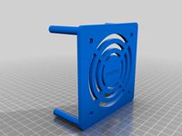
Anet A8 extruder fan and PL08N holder by egusa999
...ions in the firmware marlin2.0:
//nozzle-to-probe offsets { x, y, z }
#define nozzle_to_probe_offset { -30, -40, (your setting) }
thingiverse
free

Anet A8 Servo Z-Endstop by KillerTurtle
...fan, and uses a micro servo. i have upgraded to a ramps 1.4 board to use the servo, and using marlin rc8, with abl bilinear set.
thingiverse
free
Anet A8 Servo Z-Endstop by Avantes
... back_probe_bed_position 180
#define z_safe_homing
#define num_servos 1
z offset is set using m851 (do not forget to save m500)
thingiverse
free

Anet A8 Servo Z-Endstop Remix by averaldo
... back_probe_bed_position 180
#define z_safe_homing
#define num_servos 1
z offset is set using m851 (do not forget to save m500)
thingiverse
free
Anet A8 Probe Bracket for anet sensor by chelrix
...anet a8 probe bracket for anet sensor by chelrix
thingiverse
anet a8 probe bracket for anet official sensor and marlin firmware
thingiverse
free

Compact bowden extruder for TinyBoy and Mini Fabrikator by Lion666
...t_e2_dir true // for direct drive extruder v9 set to true, for geared extruder set to false
and the extruder needs 158 steps/mm
thingiverse
free
Sensor - Right side Anet A8 12mm by RubensCampello
...right_probe_bed_position 194
define back_probe_bed_position 170
define front_probe_bed_position 20
resolution: 0.2
infil 20 a 30%
thingiverse
free
BLtouch mount for Raise3D N2/N2+ by sylus
...org/docs/gcode/g029-mbl.html
z offset to set with you current setup could be set by a script on start gcode as :
m851 z-x.xx
m500
thingiverse
free
Anet A6 BLTouch/3DTouch mount (front) by thvranken
...isplay or with command m851) and saved to the eeprom (using the display or with command m500), in my case, this was around -2 mm.
thingiverse
free
Anet A8 right side sensor remix by smallindine
... front_probe_bed_position 20
you may need to tweak the left_probe_bed_position depending on how your x endstop switch is mounted.
Morganlowe
thingiverse
free

AM8 - 3DLS Gantry Position Tool by morganlowe
...am8 - 3dls gantry position tool by morganlowe
thingiverse
just a simple thing to set where the gantry should go!
thingiverse
free
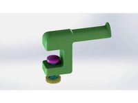
Edge Clamp Spool Holder by morganlowe
...ng. a spool holder to clamp on the edge of a desk or table. all 3d printed. fits all the spools i have ever encountered.
thanks!
thingiverse
free

Filler Jig for KING Joints by morganlowe
... joints for the larger king pre-rolls.
print upright with support everywhere on the funnel side, no support needed on the poker.
thingiverse
free
Bolt Shaped Drip Tip! by morganlowe
...eaded bolt with m12x1.25 threads for your e-cig!
see it printed here: https://youtu.be/poxalukhzve
enjoy, don't get screwed!
thingiverse
free
Panasonic Toughbook CF-U1 HDD Cover by morganlowe
...s is a cover without a caddy for the cf-u1 ssd mod
just made and tested it with my mk2 cf-u1. fits and seals properly.
thank you!
thingiverse
free
Bowden Tube Bone by morganlowe
...ides snug over the tubes and just keeps them from going nuts. i might be the only person ever to need this but here it is!
enjoy!
thingiverse
free
Trowel for 50mm Concrete Curb by morganlowe
...ts in 2 parts with 3.8mm plastite screws. kinda niche but who knows, maybe you can use it! source files included, solidworks 2017
thingiverse
free

Spark Plug Inspired Drip Tip by morganlowe
...y universal. the outside hex is 19mm and it's 20mm tall without the tank nipple. it uses a 1x7mm o ring. print with support!
thingiverse
free
Spark Plug Inspired Drip Tip Tall Version by morganlowe
...:3013945
i found these print really well upside down with no support and a nice brim to stick it down. they are very thin walled.
thingiverse
free

Lego Head Drip Tip by morganlowe
...m ring.
print in yellow!
see it printed in brown to green color change here: https://youtu.be/azx-ishzrgm
thank you and enjoy.
Marlin
3ddd
$1

Faro Marlin pendant
...mpara colgante blancohttp://www.faro.es/es/productos/marlin-lampara-colgante-blanco/
polyrate: 14107
в архиве fbx+obj
3ddd
$1

Faro Marlin bra
...
marlin black wall lamphttp://www.faro.es/en/productos/marlin-lampara-aplique-negro/
polyrate: 15491
в архиве fbx+obj
3d_export
$60

Marlin Blue 3D Model
...marlin blue 3d model
3dexport
fish sea 3ds marlin mental ray textured animals
marlin blue 3d model ojoalperro 57644 3dexport
3ddd
free

Brass Marlin
... винтаж , марлин
статуэтка марлина из латуни. винтаж.
humster3d
$15

AMC Marlin 1965 Blueprint
...65 blueprint 3d model in the format you need. all our 3d models was created on real car base and maximally close to the original.
humster3d
$75

3D model of AMC Marlin 1965
...y a detailed 3d model of amc marlin 1965 in various file formats. all our 3d models were created maximally close to the original.
cg_studio
$10

Blue marlin toon fish 3D3d model
...udio
.3ds .lwo .max .obj - blue marlin toon fish 3d 3d model, royalty free license available, instant download after purchase.
3d_export
$5

Blue marlin toon fish 3D 3D Model
...s 3d 3ds max obj lwo monster creature cartoon espadon animal aquatic
blue marlin toon fish 3d 3d model supercigale 26567 3dexport
3ddd
$1

360-panoramas_012
...360-panoramas_012 3ddd marlin studios - panoramica land & sky cd...
3ddd
$1

360-panoramas_011
...360-panoramas_011 3ddd marlin studios - panoramica land & sky cd...
A8
3d_export
$5

Audi A8 3D Model
...audi a8 3d model
3dexport
audi a8 cars car
audi a8 3d model ma 20351 3dexport
3d_export
$5

Audi A8 3D Model
...audi a8 3d model
3dexport
3d model of audi a8
audi a8 3d model badyaka 12136 3dexport
3d_ocean
$89

Audi A8 2010
...usiness car car class class f f german german luxury luxury s s s8 s8 sedan sedan vehicle vehicle
new audi a8 2010 detaled model.
3d_ocean
$45

Audi A8 restyled
...our door vehicle was created in blender3d 2.62.realistic renderings were created with yafaray 0.1.2 realistic plugin.rendering...
3d_export
$90

Audi A8 3D Model
...audi a8 3d model
3dexport
car transport vehicle
audi a8 3d model rajkmr21 103 3dexport
3d_export
$19

Audi A8 facelift 3D Model
...a8 facelift 3d model
3dexport
audi a8 oberklasse upperclass luxus german deutsch
audi a8 facelift 3d model alperabo 2321 3dexport
3d_export
$19

Audi A8 2003 3D Model
...audi a8 2003 3d model
3dexport
audi a8 oberklasse upperclass luxus german deutsch
audi a8 2003 3d model alperabo 2323 3dexport
3d_export
$99

Audi A8 2011 3D Model
...audi a8 2011 3d model
3dexport
audi a8 2010 2011 2012 2013 sedan luxury germany s8
audi a8 2011 3d model squir 21252 3dexport
3d_export
$49

Audi A8 w12 3D Model
...audi a8 w12 3d model
3dexport
audi a8 w12 sedan car german luxury s8 rs8
audi a8 w12 3d model siegfried-ukr 51463 3dexport
3d_export
$17

Audi A8 L 2013 3D Model
...audi a8 l 2013 3d model
3dexport
audi a8 2013
audi a8 l 2013 3d model cr4zydesign 68938 3dexport
Anet
thingiverse
free

Anet by derbodesign
...anet by derbodesign
thingiverse
logo anet
thingiverse
free
Anet e10 , Anet v1.0 by jonathan_943D
...anet e10 , anet v1.0 by jonathan_943d
thingiverse
soporte de ventilador de 80mm, para controladora anet v1.0
thingiverse
free
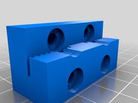
Anet A8 Anet AM8 Y belt holder
...anet a8 anet am8 y belt holder
thingiverse
anet a8 anet am8 y belt holder
thingiverse
free
Anet A8 Probe Bracket for anet sensor by chelrix
...anet a8 probe bracket for anet sensor by chelrix
thingiverse
anet a8 probe bracket for anet official sensor and marlin firmware
thingiverse
free
Anet logo by JUST3D_PRNTNG
...anet logo by just3d_prntng
thingiverse
anet logo
thingiverse
free
Fan nozzle for Anet A8 with original Anet levelsensor by peteruhlmann
...et levelsensor by peteruhlmann
thingiverse
here is an improved fan nozzle for the anet a8 with original level sensor from anet.
thingiverse
free
Anet Et4 Box
...anet et4 box
thingiverse
tool box for anet et4
thingiverse
free
Anet Logo by Superflex_Plastic_Fantastic
...anet logo by superflex_plastic_fantastic
thingiverse
anet logo to incorporate into designs.
thingiverse
free
Box for Anet ET4
...box for anet et4
thingiverse
this is a simple box for tool of anet et4
thingiverse
free

Anet V1.0 Board Kühlung (80mm Lüfter) / Anet A8 by MadCre8
...anet v1.0 board kühlung (80mm lüfter) / anet a8 by madcre8
thingiverse
anet v1.0 board kühlung (80mm lüfter) / anet a8
Guide
archive3d
free
Guide-board 3D Model
...ion sign guide sign
guide-board n170112 - 3d model (*.gsm+*.3ds) for exterior 3d visualization.
3d_ocean
$9

Guide Books 2
...ransformed separately and each have unique texture map on front and back cover. to make your work easier this model comes in t...
3d_ocean
$9

Guide Books 3
...sformed separately and each have unique texture map on front and back cover. to make your work easier this model comes in thre...
3d_export
$9
gdx80 roller guide shoe elevator parts
...gdx80 roller guide shoe elevator parts
3dexport
gdx80 roller guide shoe (elevator parts)
3d_export
$7
elevator parts guide shoes 5 specifications
...elevator parts guide shoes 5 specifications
3dexport
elevator parts, guide shoes (5 specifications)
cg_studio
$9
GBU/16 Laser Guided Bomb3d model
...ma .lwo .max .obj .xsi .c4d - gbu/16 laser guided bomb 3d model, royalty free license available, instant download after purchase.
3d_export
$16

Beginners Guide to Digital Painting 3D Model
...
magazine 2dartist 3dtotal 2d arts cg ebooks digital painting
beginners guide to digital painting 3d model 3dtotal 55459 3dexport
cg_studio
$19

Brimstone Anti-Tank Guided Missile3d model
...obj .xsi .ma .c4d - brimstone anti-tank guided missile 3d model, royalty free license available, instant download after purchase.
3d_export
$10

Time Warping In 3ds Max Complete Guide 3D Model
...ecelerate accelerate acceleration backward
time warping in 3ds max complete guide 3d model mental reality studios 21865 3dexport
3d_ocean
$20

3 Laser Guided Bombs pack - 3ds max model
...saf in order to achieve higher bombing precision of the targets. the smart munitions as it is commonly called, was made by add...
1
design_connected
$11
No 1
...no 1
designconnected
sibast no 1 computer generated 3d model. designed by sibast, helge.
3ddd
$1

1
...1
3ddd
штора
3d_export
$10

Dress 1
...dress 1
3dexport
dress 1
3d_export
$5
hinge 1
...hinge 1
3dexport
hinge 1
3ddd
$1
кресло 1
...кресло 1
3ddd
кресло 1
3ddd
$1

Штора 1
...штора 1
3ddd
штора 1
3ddd
$1

wood-1
...wood-1
3ddd
wood-1
3ddd
$1

витраж№1
...витраж№1
3ddd
витраж№1
3ddd
$1
karniz_uz 1
...karniz_uz 1
3ddd
молдинг
karniz_uz 1
3ddd
$1

royall 1
...royall 1
3ddd
сервировка
royall 1
2
design_connected
$11
No 2
...no 2
designconnected
sibast no 2 computer generated 3d model. designed by sibast, helge.
3ddd
$1

Кровать, 2 тумбочки, 2 светильника
...кровать, 2 тумбочки, 2 светильника
3ddd
кровать, 2 тумбочки, 2 светильника
нормальное качество
формат 3ds max
без текстур
3ddd
free

Кровать, 2 тумбочки, 2 светильника
...кровать, 2 тумбочки, 2 светильника
3ddd
кровать, 2 тумбочки, 2 светильника
нормальное качество
формат 3ds max
без текстур
design_connected
$27
Confluences 2 2-Seater Sofa
... 2-seater sofa
designconnected
ligne roset confluences 2 2-seater sofa computer generated 3d model. designed by nigro, philippe.
3ddd
$1
ALPEREN-2
...alperen-2
3ddd
комод , alperen-2
комод с зеркалом alperen-2
3d_export
$5

hinge 2
...hinge 2
3dexport
hinge 2
3ddd
$1

Штора 2
...штора 2
3ddd
штора 2
3ddd
$1
витраж№2
...витраж№2
3ddd
витраж№2 :-)
3ddd
$1

sculpture 2
...sculpture 2
3ddd
sculpture-2
3ddd
$1

ваза 2
...ваза 2
3ddd
ваза 2