GrabCAD
Lunar Heliostat Subsystem
by GrabCAD
Last crawled date: 1 year, 11 months ago
I am hereby proposing a subsystem that is designed to reflect sunlight into the crater, in most of the relative positions of sun, heliostat subsystem and crater.
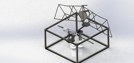
Overview
This design assembles two opposing reflecting surfaces that can move asynchronously to reflect sunlight from most possible relative locations as depicted above. The heliostat subsystem, has mechanism for degrees of freedom of movement in two axes.
The design has a closed loop kinematic chain for achieving the first degree of rotation for reflector. A worm wheel and worm gear system is assembled to rotate the crank link of the mechanism. This system is used for stowing back or as locking mechanism to withstand dynamic loads.
A rotating mechanism is designed with an extended arm for the second degree of movement of the reflector. I have added the design model of the gear train for power transfer to the arm. The main shaft is mounted inside a structural hub with the help of thrust bearing and bushing. The pinion gear transfers the power to arm base using splines that are cut on the hub of pinion gear. This power transfer system is assembled with the help of thrust ball bearings and referred the ball bearing model published by SKF.
In the two reflectors assembled, the purpose of the Secondary reflector is to redirect sunlight from the Primary reflector to the rover. An expandable span link mechanism for the secondary reflector stretches up to 3.8 m. A flexible reflecting sheet shall be wrapped on the span of links. A spiral flute cut rod shall deploy the span linkages. The primary reflector is an assembly of 4 reflecting plates and a solar array in the center. The folding reflectors will deploy by the torsion spring hinges.
Detail working mechanism:
The rotor power is transferred to the main shafts mounted at the bottom of frame inside structure hub. The main shaft rests on a thrust roller bearing. The shaft tilt is controlled with the help of a bushing mounted in the hub. A drive gear is mounted on the main shaft with the help of a flange.
The drive gear meshes with a pinion gear i.e., concentric with axis of rotation of reflector assembly. The pinion gear has a hub on which splines are machined. These splines drive the reflector assembly base component. The pinion gear is mounted on a thrust bearing. The thrust bearing is installed on a fixed plate supported on an arm attached to side face of the frame.
The base component of reflector assembly is supported by thrust bearing set up on the top of pinion gear. The reflector assembly base component is then driven by the pinion gear to orient the reflector at an appropriate angle to the Sun. The primary and secondary reflectors shall be rotated with the help of this mechanism.
The reflector assembly is mounted at the end of the arm of rotating assembly. The reflector assembly is a closed loop four bar kinematic chain. The crank link of the mechanisms is rotated by worm wheel and worm gear system. The worm gear system is driven by a motor that is mounted on top of base plate. A separate input is needed to drive this motor.
The output link of mechanism is a plate on which reflector is assembled. In case of primary reflector, a foldable plate is assembled. The folding of plates is controlled with the help of torsion spring hinges. The output link is then moved up and rotated at a certain angle controlled by crank link. Due to external loads, the output link cannot drive back the crank link as the worm gear will not drive the worm wheel and shall remain stationary.
In case of secondary reflector, an assembly of span links is mounted on output link. The span links expand by sliding one link outward. This sliding motion is executed with the help of a spiral flute cut rod. The rod is rotated with the help of a motor mounted at the end of output link. A pin follows the spiral path of the flutes in the rod and thus the link slides outward to deploy the span mechanism. The span mechanism extends up to 3.8 m. A flexible reflecting film shall be attached to the span links.
The fixed link of the kinematic chain is mounted on the frame of the subsystem with the help of a roller support slider mechanism that will allow the reflector to rotate in second axis.
The dimensions of subsystem in packaged and deployed state are present in the two images of drawing sheet uploaded with this model. The dimensions are in millimeters.
Mass properties
Mass properties of Subsystem1
Configuration: Default
Coordinate system: -- default --
* Includes the mass properties of one or more hidden components/bodies.
Mass = 474.07 kilograms
Volume = 3865.34 cubic inches
Surface area = 11.86 square meters
Center of mass: ( meters )
X = 0.58
Y = 0.55
Z = 1.20
Principal axes of inertia and principal moments of inertia: ( kilograms * square meters )
Taken at the center of mass.
Ix = ( 0.23, 0.04, 0.97) Px = 134.44
Iy = ( 0.97, -0.03, -0.23) Py = 141.56
Iz = ( 0.01, 1.00, -0.05) Pz = 176.65
Moments of inertia: ( kilograms * square meters )
Taken at the center of mass and aligned with the output coordinate system.
Lxx = 141.20 Lxy = -0.45 Lxz = 1.61
Lyx = -0.45 Lyy = 176.55 Lyz = 2.00
Lzx = 1.61 Lzy = 2.00 Lzz = 134.91
Moments of inertia: ( kilograms * square meters )
Taken at the output coordinate system.
Ixx = 973.46 Ixy = 150.17 Ixz = 330.74
Iyx = 150.17 Iyy = 1022.12 Iyz = 316.92
Izx = 330.74 Izy = 316.92 Izz = 436.45
Similar models
grabcad
free

Hub of Planetory spur Gear System.
...hub of planetory spur gear system.
grabcad
this hub is a part of jaw crusher's thrust bearing assembly.
grabcad
free

Worm gear and pinion assembly
...worm gear and pinion assembly
grabcad
an assembly i made of a worm gear
grabcad
free

Pinisi Heliostat
...solar reflector with >10 m2 reflective area. reflector using slot and hinge system. the pole can rotate 360 deg and rover too.
grabcad
free

Slat Roof Rotation Mechanism Using Worm Gear and Screw
...o link bellow show to assembly & make animation slat roof rotation mechanism using worm gear and screw in solid edge software
grabcad
free

Worm gear Reducer
... of reduction gear box which consists of a worm pinion input, an output worm gear, and features a right angle output orientation.
grabcad
free

Worm Gear And Rack Pinion Mechanism
...ad
the worm gear is introduced with rack and pinion with the connecting shaft.
designed in solidworks, and with motion analysis.
grabcad
free

DRIVE END THRUST PAD BEARING ASSEMBLY
...drive end thrust pad bearing assembly
grabcad
drive end thrust pad bearing assembly
grabcad
free

Opposite rotation mechanism with Rack & Pinion Gears
...th rack & pinion gears
mechanism animation playlist: https://www.youtube.com/playlist?list=ply-pexh5gkdpzilu-vqcmckvrsemv6aue
grabcad
free

Drive End Thrust Pad bearing Assembly for Pump assembly
... bearing. like other bearings they permanently rotate between parts, but they are designed to support a predominantly axial load.
grabcad
free

Gear and pinion Assembly
...gear and pinion assembly
grabcad
gear and pinion assembly with the help of equations
Subsystem
grabcad
free

subsystem of a CNC machine
...subsystem of a cnc machine
grabcad
subsystem of a cnc machine
grabcad
free

AP subsystem
...ap subsystem
grabcad
ap
grabcad
free

subsystem of a CNC machine
...subsystem of a cnc machine
grabcad
subsystem of a cnc machine
sistem za odvođenje strugotine
grabcad
free

Most Critical Subsystem - Clamp
...most critical subsystem - clamp
grabcad
cad for clamp subsystem
grabcad
free

Robot SubSystem Movement
...robot subsystem movement
grabcad
doesn't have idler wheel parts
grabcad
free

Mobile_Platform_Subsystem
...mobile_platform_subsystem
grabcad
subsystem
grabcad
free

Folding Solar Panel Array
...folding solar panel array grabcad hello everyone this subsystem consist of four telescopic linear slides, three actuator ,...
grabcad
free

Lunar TORCH
...lunar torch grabcad hello everyone this subsystem consist of four telescopic linear slides, three actuator ,...
grabcad
free

Mini Production Line
...line grabcad mini production line model consisting of 5 subsystem ...
Heliostat
grabcad
free

lunar heliostat
...lunar heliostat
grabcad
lunar heliostat
grabcad
free

Heliostat Challenge Backpack
...heliostat challenge backpack
grabcad
heliostat with diagonal array.
grabcad
free

MIURA-Heliostat
...miura-heliostat
grabcad
lunar torch
grabcad
free

Rollup Heliostat
... is a solar panel at the front of the box. the tilt and swivel mechanisms are at the bottom of the housing connected to the rover
grabcad
free

Half-Heliostat
... soon! design relies upon stored potential energy in "ribs" that roll out heliostat surface with no human intervention.
grabcad
free

truck heliostat
...truck heliostat
grabcad
thir truck model for in the moon
grabcad
free

Moon Heliostat
...ave enough technical details for a conceptual design.
all the detailed explanation about the heliostat is given in the pictures.
grabcad
free
Pinisi Heliostat
...solar reflector with >10 m2 reflective area. reflector using slot and hinge system. the pole can rotate 360 deg and rover too.
grabcad
free

Mobile Lunar Heliostat
...rabcad
submission for nasa challenge: lunar torch.
please watch the video (youtube link) to see all the heliostat capabilities.
grabcad
free

Lunar Heliostat
...mounted over a fixed platform or a mobile platform. as its size is tubular it can be transported in pairs to sites, and deployed.
Lunar
grabcad
free

lunar vehicle
...lunar vehicle
grabcad
lunar vehicle
grabcad
free
lunar heliostat
...lunar heliostat
grabcad
lunar heliostat
grabcad
free

Lunar gantry
...lunar gantry
grabcad
lightweight lunar gantry
grabcad
free

Lunar Torch
...lunar torch
grabcad
lunar torch rover model
grabcad
free

NASA LUNAR
...nasa lunar
grabcad
design for the nasa lunar sampling challenge
grabcad
free

lunar lander
...lunar lander
grabcad
lunar lander for e-fest competition.
grabcad
free

Lunar SpiderGantry
...ept for a lunar unloading module that is able to land on the lunar surface itself and perform the task without human intervention
grabcad
free

Portico lunar
...portico lunar
grabcad
portico lunar feito para o desafio
grabcad
free

NURUS - Lunar Masa
...nurus - lunar masa
grabcad
lunar masa
grabcad
free

Lunar Rover
...lunar rover
grabcad
apollo lunar rover
collapsible transportation used on apollo 15-17
4 wheel drive