Thingiverse

LoRaWAN Gateway case with GPS by MarkoC
by Thingiverse
Last crawled date: 3 years ago
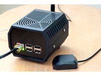
This is my redesign of the excellent case design produced by @Amedee.
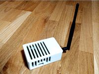
I liked the case but wanted to shuffle things around a little - moving the connectors to the rear of the chassis, and adding an indicator panel to the front.
This unit targets the GNZ Pi/iC880a backplane [1] rather than the original coredump.ch variety [2]. Additionally I wanted to add a GPS module [3].
Partial bill of materials
1 x Panel mount micro USB extender [5]
1 x iC880a LoRaWAN concentrator [4]
1 x Raspberry Pi 3 (model 2 should work fine too)
1 x GNZ Pi <-> iC880a backplane [1]
7 x 5mm LEDs (your choice of colours.. I used GRN for power, RED for PPS pulse, BLU for concentrator status
1 x GY-NEO6MV2 Ublox GPS module + ceramic antenna [eg 6]
1 x 20mm pitch Veroboard for mounting LEDs
1 x 30mm x 15mm 5V case fan
Wire, 2.5mm, 3mm screws/nuts etc
Filament - I used Rigid Ink blue PLA for the plates, Florence Tech Marble for the top and bottom, Florence Tech TPU for the feet.
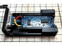
Backplate
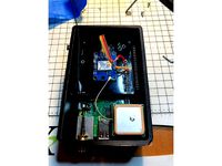
I wanted all the connections on the rear of the device. Here we have the Raspi connectors bottom right, power socket bottom left. As this setup is all 5V, I chose a micro-USB power input. The official Raspberry Pi PSU works well.
Along the top are 30mm fan and antenna SMA connector. The GNZ backplane is dumb and doesn't support fan control; I just wire it directly to 5V.
Base
Nothing clever here, just a nice solid base.
Top
The case top has mounts for the GPS module and a holder for the antenna. You may want to use a spot of glue, blue tack or double-sided tape to secure the antenna. Remember to fit it "upside down" so the top faces up when assembled ;)
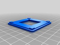
Front Panel
Mount the LEDs to the strip board per your preference. The circuit is simple, just a common GND line with 1k resistors in series with each LED. You may want to vary the resistor values to balance the brightness if you're using different colours. I didn't bother.
I hooked up the connections as follows:
Function Line LED Colour Cable iC880a Pin
POW 1 (Green) ORANGE 21
BACKHAUL PKT 2 (Blue) YELLOW 7
TX PKT 3 (Blue) GREEN 8
RX SENSOR PKT 4 (Blue) BLUE 10
RX FSK PKT 5 (Blue) PURPLE 9
RX BUF !EMPTY 6 (Blue) GREY 11
GPS PPS 7 (Red) WHITE 19
GND 8 (N/A) BLACK 1
PPS is the "pulse per second' GPS output which synchronises the iC880a internal clock. Unfortunately the board doesn't expose this; you need to solder direct to pin 3 on the Neo6 itself (see photos).
[1] https://www.tindie.com/products/gnz/imst-ic880a-lorawan-backplane-kit/
[2] https://shop.coredump.ch/product/ic880a-lorawan-gateway-backplane/
[3] https://www.u-blox.com/sites/default/files/products/documents/NEO-6_DataSheet_(GPS.G6-HW-09005).pdf
[4] http://shop.imst.de/wireless-modules/lora-products/8/ic880a-spi-lorawan-concentrator-868-mhz
[5] https://www.modmypi.com/raspberry-pi/accessories-198/output-adaptors/panel-mount-651/panel-mount-micro-usb-male-to-female
[6] https://www.ebay.co.uk/itm/GY-NEO6MV2-Ublox-GPS-Module-with-Active-Antenna-and-header-pins/231859809745?hash=item35fbebedd1:g:YLsAAOSwoydWsLIc
I liked the case but wanted to shuffle things around a little - moving the connectors to the rear of the chassis, and adding an indicator panel to the front.
This unit targets the GNZ Pi/iC880a backplane [1] rather than the original coredump.ch variety [2]. Additionally I wanted to add a GPS module [3].
Partial bill of materials
1 x Panel mount micro USB extender [5]
1 x iC880a LoRaWAN concentrator [4]
1 x Raspberry Pi 3 (model 2 should work fine too)
1 x GNZ Pi <-> iC880a backplane [1]
7 x 5mm LEDs (your choice of colours.. I used GRN for power, RED for PPS pulse, BLU for concentrator status
1 x GY-NEO6MV2 Ublox GPS module + ceramic antenna [eg 6]
1 x 20mm pitch Veroboard for mounting LEDs
1 x 30mm x 15mm 5V case fan
Wire, 2.5mm, 3mm screws/nuts etc
Filament - I used Rigid Ink blue PLA for the plates, Florence Tech Marble for the top and bottom, Florence Tech TPU for the feet.
Backplate
I wanted all the connections on the rear of the device. Here we have the Raspi connectors bottom right, power socket bottom left. As this setup is all 5V, I chose a micro-USB power input. The official Raspberry Pi PSU works well.
Along the top are 30mm fan and antenna SMA connector. The GNZ backplane is dumb and doesn't support fan control; I just wire it directly to 5V.
Base
Nothing clever here, just a nice solid base.
Top
The case top has mounts for the GPS module and a holder for the antenna. You may want to use a spot of glue, blue tack or double-sided tape to secure the antenna. Remember to fit it "upside down" so the top faces up when assembled ;)
Front Panel
Mount the LEDs to the strip board per your preference. The circuit is simple, just a common GND line with 1k resistors in series with each LED. You may want to vary the resistor values to balance the brightness if you're using different colours. I didn't bother.
I hooked up the connections as follows:
Function Line LED Colour Cable iC880a Pin
POW 1 (Green) ORANGE 21
BACKHAUL PKT 2 (Blue) YELLOW 7
TX PKT 3 (Blue) GREEN 8
RX SENSOR PKT 4 (Blue) BLUE 10
RX FSK PKT 5 (Blue) PURPLE 9
RX BUF !EMPTY 6 (Blue) GREY 11
GPS PPS 7 (Red) WHITE 19
GND 8 (N/A) BLACK 1
PPS is the "pulse per second' GPS output which synchronises the iC880a internal clock. Unfortunately the board doesn't expose this; you need to solder direct to pin 3 on the Neo6 itself (see photos).
[1] https://www.tindie.com/products/gnz/imst-ic880a-lorawan-backplane-kit/
[2] https://shop.coredump.ch/product/ic880a-lorawan-gateway-backplane/
[3] https://www.u-blox.com/sites/default/files/products/documents/NEO-6_DataSheet_(GPS.G6-HW-09005).pdf
[4] http://shop.imst.de/wireless-modules/lora-products/8/ic880a-spi-lorawan-concentrator-868-mhz
[5] https://www.modmypi.com/raspberry-pi/accessories-198/output-adaptors/panel-mount-651/panel-mount-micro-usb-male-to-female
[6] https://www.ebay.co.uk/itm/GY-NEO6MV2-Ublox-GPS-Module-with-Active-Antenna-and-header-pins/231859809745?hash=item35fbebedd1:g:YLsAAOSwoydWsLIc
Similar models
thingiverse
free
Case for iC880a plus NEO6MV2 GPS module by MarkoC
...unt the gps antenna on the 'shelf' using double-sided tape. the neo6 module can fit between the backplate and the ic880a.
thingiverse
free
iC880a Raspberry Pi case by berkutta
... pi, ic880a adapter board from gnz and ic880a concentrator in one simple case. this design is made for 1.2mm self tapping screws.
thingiverse
free

iC880A / RPi LoRaWAN Gateway Holder by dbrgn
...//github.com/ttn-zh/ic880a-gateway/wiki
screw the raspberry pi and the concentrator board to the holder using spacers and screws.
thingiverse
free

Ublox 6m case by histo
...om readytoflyquads. case has a cut out for better antenna reception and a hole for mounting a piece of glue stick to diffuse led.
thingiverse
free

Enclosure for DIY LoraWAN Gateway based on ch2i Backplane by jenssiebert
...ning in the bottom part of the enclosure to allow for the connection of a micro usb cable as a power source for the raspberry pi.
thingiverse
free
RTFquads Ublox 6M case by extera
...sible.
mount the pcb with 3m hex screws (6mm).
you might need to add a washer. i recommend using a nylon washer. (or print one)
grabcad
free

Ublox GPS Module With Compass GPS Antenna
...ublox gps module with compass gps antenna
grabcad
ublox 6m high precision rc quadcopter gps module with compass gps antenna
thingiverse
free

LoRaWAN Gateway for Raspberry Pi and ic880a Box and Lid for 40x40x20mm fan
...tetra pak material)
github for the code and complete hardware setup:https://github.com/ruslanabdulin1985/lora-gateway-rapberry-pi
thingiverse
free

tbs caipirinha II gps mount by Darren_46
...ht i would print a little mount !
gps module i used was :
hglrc neo-m8n m8m ublox 8 tiny gps and glonass receiver module for inav
thingiverse
free

Ublox 7M GPS Module Case by CCX2001
...ublox 7m gps module case by ccx2001
thingiverse
its a small case for a ublox 7m gps module.
Markoc
thingiverse
free
Gigatron game port adapter by MarkoC
...a simple case to hold an arduino nano, used for programming the gigatron kit as described here: https://gigatron.io/?page_id=574
thingiverse
free
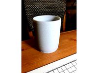
Toothbrush holder by MarkoC
... to drink from, the 3d printing safety police will be all over you ;)
looks really nice in marble pla and matches my tesco stuff.
thingiverse
free

Filament Sample Tray by MarkoC
... full of them.
so, print this in white and write in the brand/plastic in permanent ink. a drop of glue keeps the cubes in place.
thingiverse
free
Case for iC880a plus NEO6MV2 GPS module by MarkoC
...unt the gps antenna on the 'shelf' using double-sided tape. the neo6 module can fit between the backplate and the ic880a.
thingiverse
free

Delta BL Touch mount by MarkoC
...ly there's limited room on the build for it.
i sacrificed one of the part heating vents and designed this to drop in instead.
thingiverse
free

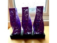
TARDIS lamp by MarkoC
...ly just scale the base in height to fit. the hole on the front is to guide the ir to the sensor.
note: scale the tardis to 135%.
thingiverse
free

LoRaWAN Sensor Node by MarkoC
...://www.adafruit.com/product/1904
[2] https://www.amazon.co.uk/haljia-gy-bme280-3-3-precision-barometric-temperature/dp/b01mud07sx
thingiverse
free
Modular Base for Lamp by MarkoC
...and use double-sided tape inside the base to keep the lights in place.
best printed end-on with the small (rear) hole at the top.
thingiverse
free
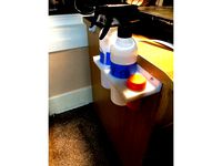
Spray + Talc Holder by MarkoC
...ur pei. if you happen to use these accessories, great! if not read up before you decide to give them a try. pei can be finicky...
thingiverse
free

GRA AFCH IN-14 Nixie Clock by MarkoC
...r-nixie-tubes-clocks-in-14/
nb: the unit generates high voltage to power the nixies!
don’t poke at the buttons with your fingers!
Lorawan
thingiverse
free

LoRaWan Weather Station Case by henri98
...thingsnetwork.org/labs/story/lorawan-weather-station-weather-underground/
code: https://github.com/henri98/lorawanweatherstation
thingiverse
free

LoRawan gateway external mount, Dragino LPS-8
...network). it is pretty basic but seems to do a good enough job on protecting it from the elements.
i recommend printing in petg.
thingiverse
free
Enclosure for LoraWan TTN Gateway: Raspberry Pi + RAK831 by Amedee
...oard you will need:
4 m2.5x12 to secure the raspberry pi
4 m3x8 + 3 m3 nuts for the feet
4 m3x8 round head to close the enclosure
thingiverse
free

Sensorcase BME280, CH2i, LoRaWAN, Arduino pro mini by sbiermann
...na.
see here for more details: https://www.thethingsnetwork.org/forum/t/lora-bme280-environmental-node-with-webbased-backend/9264
thingiverse
free

LoraWAN antenna 868 MHz
... is 1.6 mm copper wire without isolation. here the coil is 12 turns again on 6 mm drill. radials and printed parts are unchanged.
thingiverse
free
LoRaWAN Gateway for Raspberry Pi and ic880a Box and Lid for 40x40x20mm fan
...tetra pak material)
github for the code and complete hardware setup:https://github.com/ruslanabdulin1985/lora-gateway-rapberry-pi
thingiverse
free

Clip-On Wandhalterung / Wallmount LoraWAN Gateway Dragino LG02 by axel_ch
...ars and difficult to reach. after attaching the wallmount switch on the gateway and attach the cables and snap it into the mount.
thingiverse
free

External mount/cover for Dragino LPS-8 "the thing network" LoRaWan gateway
...awan gateway. it is fairly basic but sufficient i think to protect the gateway from rain etc...
print in petg for uv resistance.
thingiverse
free

LoraWan GateWay OutDoor backplane by Marten
...s..
https://github.com/mirakonta/lora_gateway/wiki
updates expected http://svn.martenvijn.nl/svn/lora/
made @ makerspace leiden..
thingiverse
free
iC880A / RPi LoRaWAN Gateway Holder by dbrgn
...//github.com/ttn-zh/ic880a-gateway/wiki
screw the raspberry pi and the concentrator board to the holder using spacers and screws.
Gateway
turbosquid
$45
gateway
... 3d model gateway for download as max, max, max, obj, and fbx on turbosquid: 3d models for games, architecture, videos. (1548206)
turbosquid
$36

p0011 - gateway
...id
royalty free 3d model p0011 - gateway for download as obj on turbosquid: 3d models for games, architecture, videos. (1292778)
turbosquid
$20

bamboo gateway
...uid
royalty free 3d model bamboo gateway for download as skp on turbosquid: 3d models for games, architecture, videos. (1595645)
turbosquid
$60

Gateway of India
... available on turbo squid, the world's leading provider of digital 3d models for visualization, films, television, and games.
turbosquid
$5

Dimensional Gateway
... available on turbo squid, the world's leading provider of digital 3d models for visualization, films, television, and games.
turbosquid
$5

Rounded Gateway
...rounded gateway for download as 3ds, obj, fbx, blend, and dae on turbosquid: 3d models for games, architecture, videos. (1491072)
turbosquid
$5
Rectangle Gateway
...ctangle gateway for download as 3ds, obj, fbx, blend, and dae on turbosquid: 3d models for games, architecture, videos. (1491067)
turbosquid
$5

Octagon Gateway
...octagon gateway for download as 3ds, obj, fbx, blend, and dae on turbosquid: 3d models for games, architecture, videos. (1491064)
turbosquid
$2

Gateway plasma
... available on turbo squid, the world's leading provider of digital 3d models for visualization, films, television, and games.
3d_export
$50
Gateway of India 3D Model
...gateway of india 3d model
3dexport
gateway on india indiagate
gateway of india 3d model rohan gaikwad 20944 3dexport
Gps
3ddd
free
Подавитель GPS
...подавитель gps
3ddd
подавитель gps
3ddd
free

Подавитель GPS
...подавитель gps
3ddd
подавитель gps
3ddd
free

Cтол GP
...cтол gp
3ddd
обеденный , giorgio piotto
cтол gp
turbosquid
$5
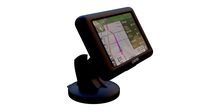
GPS navigation
...e 3d model gps navigation for download as blend, fbx, and obj on turbosquid: 3d models for games, architecture, videos. (1636695)
turbosquid
$4
GP-5
...lty free 3d model gp-5 for download as 3ds, max, obj, and fbx on turbosquid: 3d models for games, architecture, videos. (1160699)
turbosquid
$60
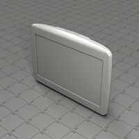
TomTom GPS
... available on turbo squid, the world's leading provider of digital 3d models for visualization, films, television, and games.
turbosquid
free

GPS/TV
... available on turbo squid, the world's leading provider of digital 3d models for visualization, films, television, and games.
3d_export
$5

Battery GP 3D Model
...battery gp 3d model
3dexport
battery gp
battery gp 3d model wasiliy 40319 3dexport
3d_export
$5

gas mask gp-5
...gas mask gp-5
3dexport
gas mask gp-5
cg_studio
$36

Gps device3d model
...ice3d model
cgstudio
.3ds .c4d .dxf .obj - gps device 3d model, royalty free license available, instant download after purchase.
Case
3d_export
$1
case
...case
3dexport
case
archibase_planet
free
Case
...case
archibase planet
showcase show-case glass case
glass-case + cakes - 3d model for interior 3d visualization.
archibase_planet
free
Case
...case
archibase planet
showcase show-case glass case
glass-case for chips - 3d model for interior 3d visualization.
archibase_planet
free
Case
...case
archibase planet
case shelving drawer
case - 3d model for interior 3d visualization.
archibase_planet
free
Case
...case
archibase planet
case rack locker
case - 3d model for interior 3d visualization.
archibase_planet
free
Case
...case
archibase planet
case drawer kitchen furniture
case - 3d model for interior 3d visualization.
archibase_planet
free
Case
...case
archibase planet
case cupboard shelving
glass case - 3d model for interior 3d visualization.
archibase_planet
free
Case
...case
archibase planet
case handbag suitcase
case - 3d model (*.gsm+*.3ds) for interior 3d visualization.
archibase_planet
free
Case
...case
archibase planet
case suitcase
case 5 - 3d model (*.gsm+*.3ds) for interior 3d visualization.
archibase_planet
free
Case
...case
archibase planet
locker case dresser
case - 3d model (*.gsm+*.3ds) for interior 3d visualization.