Thingiverse
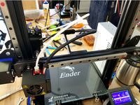
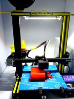
Linear Rail Z Axis Mod for Ender 3 by bamoore01
by Thingiverse
Last crawled date: 3 years ago
Note: Check out the 1.22.21 update for this mod below.
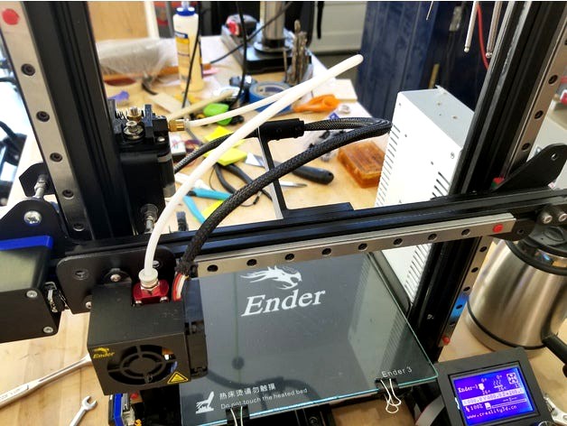
8.5.18 - I've re-designed this mod completely from the original version that I had out here. That version had the X gantry attached to the linear bearings with printed plastic adapters. I was worried how stiff that set up would be and it turns out I should have been more worried. It quite literally was crap. All of the original design is gone.
The way I did this mod was to mount the linear rails to the front of the vertical posts and attach then directly to the metal plates that hold wheels and X gantry. Since there are no soft attachments with plastic it makes for a solid mod. You will have to print the right and left templates to drill the bearing block mounting holes and a new Z limit switch holder.
The result of moving the bearings out to the front of the vertical posts is that the X gantry, X gantry mounting plate and the hot end are moved out by 9.25mm. Moving the hot end may require moving the Y axis limit switch. For me that was not problem since I did the Y linear rail mod and could simply move the Y limit switch to accommodate for the shift in the Y. To maintain the geometry of the Z lead screw, the back X gantry mounting plate needs to stay in the same place. I did this by removing the three axle screws and replacing them with screws that were 10 mm longer leaving the ability to adjust the position of the back plate.
On the original Creality design the X gantry is fixed at both ends to the mounting plates with no allowance for adjustment. That works fine but I changed the right side a bit to allow a final adjustment to be made on the X gantry to right X gantry plate with T-Nuts. It simply allows for a little error in measurement and execution since we all don’t have CNC machines to make holes exactly where they should be.
Notes;
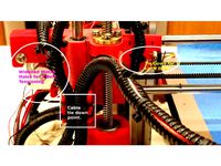
All of the positioning of the right and left front X gantry plates is pretty much fixed by the geometry of the linear rails and bearings when they are connected and fastened to the vertical rails. That’s not the case for the left side rear plate that is connected to the Z lead screw. That plate needs to stay in its original place and since the front plate moved by 9.25mm the space between the left plates needs to increase by that much. That is not a problem on the right side since there is no rear plate. I thought the best way to handle that was to simply make the spacing adjustable. If you look at the pictures you will see that I used the extra Nylock nuts that came off of the axles to clamp each plate. This way I can fairly easily adjust the space between the two plates. The front plate is fixed so the adjustment nuts can be used to move the back plate forward or back to make sure that the lead screw is the same distance from the vertical post at the top and bottom of the screw and that the two plates are separated equally at all three axle points. I think that using the spaces as I did helps stiffen the entire front/back assembly so use them if you can. Notice that I used the eccentric nut on the back of the inside axle on the right side of the left plates. This is because that hole is bigger that the rest for the eccentric nut on the original design and the eccentric nut works perfectly.
As I mentioned, I did the other two axis mods already so I had a lot of spare parts to use for this. You may or may not have to get more parts.
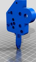
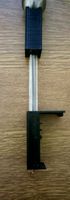
Left Drill Template. You have to remove the left side front plate from the printer. Use the 5mm axle screws to attach the drill guide to the plate using the two holes marked A. Drill out the four B holes through the left front metal plate with a 3mm or 1/8” drill bit. The result will be that the bearing block will attach to the plate just below the X gantry. It is best if you can use a drill press to help guarantee that the holes are straight.
Right Drill Template. Remove the right side font plate and attach it to the template using the three 5mm axle screws through the holes marked A. Drill the right plate through the B hole with a 5mm drill bit (3/16” may work, if not use a 13/64” if you don’t have metric bits). Drill the holes marked C with a 3mm or 1/8” drill bit.
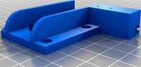
Limit Switch Adapter. This is easy to replace. Just unscrew the original and put this one on. It will move the limit switch out 9.25mm. Obviously it will have to be adjusted before you retram you plate.
Taking it apart is easy. Just unscrew things. Putting it back together can be a challenge. Things have to get put together in the right order or you take it back apart again. The most important one is the two screws that hold the X gantry to the left front plate. They go on and get tightened first. You can’t get to the after the plate is attached to the bearing.
Adjustment. There are some things to watch for here. On my machine the vertical posts were turned a little. It didn’t bother the wheels much but the linear bearings don’t like it. The best way to handle that is after everything is nice and snug and with the gantry at the bottom of its travel, loosen the bottom two screws and top two screws on the left side only. While the four screws loose, loosen the three 5mm T-Nuts on the right X gantry plate to X gantry and retighten. Then retighten the 4 screws at the top and bottom of the post. Then do the same to the right side including loosening and tightening the 4 T Nuts. That should square the posts and set the bottom spread. After that is done, move the gantry to the top of travel and loosen all 4 of the top screws only and tighten. This should set the post spread.
After the posts are set you should make sure the X gantry is square to the posts. The best way to do this is to loosen the four 3mm screws holding the left front plate to the bearing block and the three 5mm T Nuts on the right side of the X gantry. Then clamp a square to one of the posts and the X gantry. Then tighten the four 3mm screws and the three 5mm T Nuts.
Parts List;
Rails
2 x 350mm mgn12 Linear Rails with mgn12H blocks. I got mine from Amazon.
24 x M3x8mm Hex Socket Cap Screws. Attaching linear rails to upright posts.
24 x M3 T-Nuts. Attaching linear rails to upright posts.
Left Side
4 x M3x6mm Hex Socket Cap Screws. (Attach left plate to bearing block)
3 x M5x50mm Screw for the three Wheel Axel Spacers
9 x M5 Nylock nuts ( I had plenty of these as spares from the linear rail mods)
5 x M5 spacers (These came from the linear rail mods also. Could use a washer)
1 x eccentric nut (from the inside Wheel Axel)
Printed Left Plate Template
Right Side
4 x M3x6mm Hex Socket Cap Screws. (Attach right plate to bearing block)
3 x M5x6mm Screw
3 x M5 T-Nuts
Printed Right Plate Template
Limit Switch Adapter
Printed Z Axes Limit Switch Adapter
Rev History;
8.12.18 Added Limit Switch Adapter V2. Moves the limit switch out 10mm so that it hits on the metal Left X Gantry Plate instead of the rubber wiper on the end of the bearing block.
8.13.18 V2 of the Limit Switch Adapter had problems. Replace with V3.
12.17.18 Replaced V3 of the Limit Switch Adapter with V4. Some people were having trouble splitting/printing the adapter. There was a problem with the STL so I rebuilt it. There is no difference in the final size and shape so if you printed the V3 file there is no need to print the V4 file.
4.6.20 I've had some requests for a CAD file of the drill plate so people could use it to cut new plates so I've included a DXF of that drawing.
1.22.21 I just added a dual z drive kit to my printer. I used the kit from BCZAMD on Amazon. It's a little over priced for all the parts but I guess I didn't feel like hunting down all the parts separately. A while back I added direct drive to my printer. I was never really happy with the results. It seemed like I was getting more banding with the direct drive mod. So.. I finally did a little checking. I disconnected the drive screw so the gantry moved freely on the z axis. What I found is that lifting the gantry from where the screw lifts the movement was noticeably smoother when the print head was on the left side of the gantry compared to the right side of the gantry. This really isn't that surprising if you think about it.
I can't say what the same experiment would be with a stock print head. So I installed the dual drive kit. This is the one that has a belt across the top connecting the two Z screws and uses the original motor only. Prints are noticeably improved. No more banding. I think I finally got this printer printing how I want. One note about the kit. The Ender 3 is not a perfectly aligned machine (huh??????). On mine the right side lift screw from the kit did not align with the top support bearing from the kit. I was bad enough that the gantry would not travel all the way to the top before binding. I had to file the top bracket holes into slots so I could move the bracket to the left a little more that 1 mm. Not a big deal but not the fault of the conversion kit. I also tried the aluminum bearing blocks you can get separately. They are close but also can be a little off in the Y direction so you might have to shim them out or file them down (maybe).
8.5.18 - I've re-designed this mod completely from the original version that I had out here. That version had the X gantry attached to the linear bearings with printed plastic adapters. I was worried how stiff that set up would be and it turns out I should have been more worried. It quite literally was crap. All of the original design is gone.
The way I did this mod was to mount the linear rails to the front of the vertical posts and attach then directly to the metal plates that hold wheels and X gantry. Since there are no soft attachments with plastic it makes for a solid mod. You will have to print the right and left templates to drill the bearing block mounting holes and a new Z limit switch holder.
The result of moving the bearings out to the front of the vertical posts is that the X gantry, X gantry mounting plate and the hot end are moved out by 9.25mm. Moving the hot end may require moving the Y axis limit switch. For me that was not problem since I did the Y linear rail mod and could simply move the Y limit switch to accommodate for the shift in the Y. To maintain the geometry of the Z lead screw, the back X gantry mounting plate needs to stay in the same place. I did this by removing the three axle screws and replacing them with screws that were 10 mm longer leaving the ability to adjust the position of the back plate.
On the original Creality design the X gantry is fixed at both ends to the mounting plates with no allowance for adjustment. That works fine but I changed the right side a bit to allow a final adjustment to be made on the X gantry to right X gantry plate with T-Nuts. It simply allows for a little error in measurement and execution since we all don’t have CNC machines to make holes exactly where they should be.
Notes;
All of the positioning of the right and left front X gantry plates is pretty much fixed by the geometry of the linear rails and bearings when they are connected and fastened to the vertical rails. That’s not the case for the left side rear plate that is connected to the Z lead screw. That plate needs to stay in its original place and since the front plate moved by 9.25mm the space between the left plates needs to increase by that much. That is not a problem on the right side since there is no rear plate. I thought the best way to handle that was to simply make the spacing adjustable. If you look at the pictures you will see that I used the extra Nylock nuts that came off of the axles to clamp each plate. This way I can fairly easily adjust the space between the two plates. The front plate is fixed so the adjustment nuts can be used to move the back plate forward or back to make sure that the lead screw is the same distance from the vertical post at the top and bottom of the screw and that the two plates are separated equally at all three axle points. I think that using the spaces as I did helps stiffen the entire front/back assembly so use them if you can. Notice that I used the eccentric nut on the back of the inside axle on the right side of the left plates. This is because that hole is bigger that the rest for the eccentric nut on the original design and the eccentric nut works perfectly.
As I mentioned, I did the other two axis mods already so I had a lot of spare parts to use for this. You may or may not have to get more parts.
Left Drill Template. You have to remove the left side front plate from the printer. Use the 5mm axle screws to attach the drill guide to the plate using the two holes marked A. Drill out the four B holes through the left front metal plate with a 3mm or 1/8” drill bit. The result will be that the bearing block will attach to the plate just below the X gantry. It is best if you can use a drill press to help guarantee that the holes are straight.
Right Drill Template. Remove the right side font plate and attach it to the template using the three 5mm axle screws through the holes marked A. Drill the right plate through the B hole with a 5mm drill bit (3/16” may work, if not use a 13/64” if you don’t have metric bits). Drill the holes marked C with a 3mm or 1/8” drill bit.
Limit Switch Adapter. This is easy to replace. Just unscrew the original and put this one on. It will move the limit switch out 9.25mm. Obviously it will have to be adjusted before you retram you plate.
Taking it apart is easy. Just unscrew things. Putting it back together can be a challenge. Things have to get put together in the right order or you take it back apart again. The most important one is the two screws that hold the X gantry to the left front plate. They go on and get tightened first. You can’t get to the after the plate is attached to the bearing.
Adjustment. There are some things to watch for here. On my machine the vertical posts were turned a little. It didn’t bother the wheels much but the linear bearings don’t like it. The best way to handle that is after everything is nice and snug and with the gantry at the bottom of its travel, loosen the bottom two screws and top two screws on the left side only. While the four screws loose, loosen the three 5mm T-Nuts on the right X gantry plate to X gantry and retighten. Then retighten the 4 screws at the top and bottom of the post. Then do the same to the right side including loosening and tightening the 4 T Nuts. That should square the posts and set the bottom spread. After that is done, move the gantry to the top of travel and loosen all 4 of the top screws only and tighten. This should set the post spread.
After the posts are set you should make sure the X gantry is square to the posts. The best way to do this is to loosen the four 3mm screws holding the left front plate to the bearing block and the three 5mm T Nuts on the right side of the X gantry. Then clamp a square to one of the posts and the X gantry. Then tighten the four 3mm screws and the three 5mm T Nuts.
Parts List;
Rails
2 x 350mm mgn12 Linear Rails with mgn12H blocks. I got mine from Amazon.
24 x M3x8mm Hex Socket Cap Screws. Attaching linear rails to upright posts.
24 x M3 T-Nuts. Attaching linear rails to upright posts.
Left Side
4 x M3x6mm Hex Socket Cap Screws. (Attach left plate to bearing block)
3 x M5x50mm Screw for the three Wheel Axel Spacers
9 x M5 Nylock nuts ( I had plenty of these as spares from the linear rail mods)
5 x M5 spacers (These came from the linear rail mods also. Could use a washer)
1 x eccentric nut (from the inside Wheel Axel)
Printed Left Plate Template
Right Side
4 x M3x6mm Hex Socket Cap Screws. (Attach right plate to bearing block)
3 x M5x6mm Screw
3 x M5 T-Nuts
Printed Right Plate Template
Limit Switch Adapter
Printed Z Axes Limit Switch Adapter
Rev History;
8.12.18 Added Limit Switch Adapter V2. Moves the limit switch out 10mm so that it hits on the metal Left X Gantry Plate instead of the rubber wiper on the end of the bearing block.
8.13.18 V2 of the Limit Switch Adapter had problems. Replace with V3.
12.17.18 Replaced V3 of the Limit Switch Adapter with V4. Some people were having trouble splitting/printing the adapter. There was a problem with the STL so I rebuilt it. There is no difference in the final size and shape so if you printed the V3 file there is no need to print the V4 file.
4.6.20 I've had some requests for a CAD file of the drill plate so people could use it to cut new plates so I've included a DXF of that drawing.
1.22.21 I just added a dual z drive kit to my printer. I used the kit from BCZAMD on Amazon. It's a little over priced for all the parts but I guess I didn't feel like hunting down all the parts separately. A while back I added direct drive to my printer. I was never really happy with the results. It seemed like I was getting more banding with the direct drive mod. So.. I finally did a little checking. I disconnected the drive screw so the gantry moved freely on the z axis. What I found is that lifting the gantry from where the screw lifts the movement was noticeably smoother when the print head was on the left side of the gantry compared to the right side of the gantry. This really isn't that surprising if you think about it.
I can't say what the same experiment would be with a stock print head. So I installed the dual drive kit. This is the one that has a belt across the top connecting the two Z screws and uses the original motor only. Prints are noticeably improved. No more banding. I think I finally got this printer printing how I want. One note about the kit. The Ender 3 is not a perfectly aligned machine (huh??????). On mine the right side lift screw from the kit did not align with the top support bearing from the kit. I was bad enough that the gantry would not travel all the way to the top before binding. I had to file the top bracket holes into slots so I could move the bracket to the left a little more that 1 mm. Not a big deal but not the fault of the conversion kit. I also tried the aluminum bearing blocks you can get separately. They are close but also can be a little off in the Y direction so you might have to shim them out or file them down (maybe).
Similar models
thingiverse
free

OneUp Printer X Gantry Mod by 3DPengn
...t drill holes for x motor
some drilling maybe required to enlarge any hole in print not big enough, due to poor printing quality.
thingiverse
free

Ender 3 X Axis Linear Rails Plate Extended by jagerkti
...en the carriage holes and the hotend mounting holes by 3mm. this allowed be to get a nut in the back to attach the hotend easily.
thingiverse
free

x_Axis_motor_linear_Screw by m3lvm
...ouling the linear rails.
the hole depth for the linear rails is 39mm. and you will have to make allowance for this when upgrading
thingiverse
free
Hictop Left Side X & Z Axis Lift Screw by chaoren
... that you can tie down the wire coming off of the x limit switch so it doesn't break.
i recommend 100% infill printed in abs.
thingiverse
free

Anet A6 Z-axis limit switch adjuster by Henkolizer
... all fit. also the mounting holes of the limit switch are too small. i used a 1,5mm drill to make the screws fit.
happy printing!
thingiverse
free
Bondtech LGX for Flexible to CR-10 Plate Linear Rail Mod by Presti
...r-10 y carriadge plate, previously drilled to be attached to a mgn12h linear rail.
needs to be post processed to drill m3 holes.
thingiverse
free

Ender 5 - Y Limit Switch to back frame mount by dkalinai
...rews i recommend you temporarily take out the one holdin down the frame. can be put back after one m4 t-nut screw is in position.
thingiverse
free

CR10s Pro Linear Rail Mod by Bozo76
...m rails
profile 20x20x50 min 3pce
m3 t-nuts
m3x8 hex screws
m5 hex screws to attache the 20x20 profiles on the x-gantry
m5 t-nuts
thingiverse
free
Z-axis_linear_rails_MGN12H by Far_a_way
...justment.
if necessary, extend the cable and tube.
reattach the dismantled components of the x-axis, lower the x-axis and adjust.
thingiverse
free

Y-Axis Linear Bearing Mod MGN12H for Ender 3 V2 by ngungbi
... then tighten the rail screw at the rear.
make sure the carriage can move freely with very little resistance.
reassemble the bed.
Bamoore01
thingiverse
free

Digitrax UT Throttle Table Mounts by bamoore01
...e little clips that are just for holding the extra cable up off the floor. they are meant to hold the coiled cable from the ut4.
thingiverse
free

Aquila Sailplane by bamoore01
...o real profile change so i did not change the version number.
05.06.21: added the fuse with no cavity or launch hook.
..........
thingiverse
free

Hobie Hawk Sailplane by bamoore01
...n at 110 (bread proof on out oven) but that cause a lot of problems like sagging fuse and stab.
.................................
thingiverse
free

Filament Guide for Creality Ender 3 by bamoore01
...ip it down over the z axis screw. it keeps the filament off of the greasy screw without putting additional bend on the filament.
thingiverse
free

White Board Magnetic Marble Track by bamoore01
...n a weaker grab. the 33+ is 7 mils. if you want more grab, a second magnet can be dropped into each hole. that helps a little.
thingiverse
free
Linear Rail X Axis Mod for Ender 3 by bamoore01
...ving problems printing it.
12.28.18 - replaced belt adapter v2 with v3. v3 is a little stronger and the stl is a little cleaner.
thingiverse
free

X-Axis Stepper cover w/ integrated Micro-Switch Mount for Linear Mod
...#lazy. x-axis stepper cover https://www.thingiverse.com/thing:3271077 x-linear mod is from @bamoore01 ...
Linear
3ddd
$1
Linear Diffusers
...linear diffusers
3ddd
диффузор
set of linear diffusers for ceiling.
design_connected
$27

Linear Sofa
...linear sofa
designconnected
scp linear sofa computer generated 3d model.
design_connected
$18

Atlantis linear
...atlantis linear
designconnected
terzani atlantis linear pendant lights computer generated 3d model. designed by barlas baylar.
3d_export
$5
light linear unit
...light linear unit
3dexport
light linear unit
turbosquid
$5

Linear Actuator
...
royalty free 3d model linear actuator for download as blend on turbosquid: 3d models for games, architecture, videos. (1589061)
turbosquid
$29
Linear panel
...oyalty free 3d model linear panel for download as max and obj on turbosquid: 3d models for games, architecture, videos. (1391254)
turbosquid
$12
Linear Chandelier
...y free 3d model linear chandelier for download as max and obj on turbosquid: 3d models for games, architecture, videos. (1574289)
turbosquid
$10

Grohe Lineare
... available on turbo squid, the world's leading provider of digital 3d models for visualization, films, television, and games.
turbosquid
$10

Linear Axis
... available on turbo squid, the world's leading provider of digital 3d models for visualization, films, television, and games.
3d_export
$5

Linear Unit 3D Model
...linear unit 3d model
3dexport
linear unit force torque velocity
linear unit 3d model fau 71218 3dexport
Ender
3ddd
$1
Enders / Elegance
...enders / elegance
3ddd
обогреватель
уличный газовый обогреватель enders elegance
высота: 2200 мм
3d_export
free
ender 3 frame cavity covers
... of the creality ender 3 - makes it look a bit more attractive it just slides into the open channels of the aluminium framework
turbosquid
$1
pen support for ender 3
...y free 3d model pen support for ender 3 for download as blend on turbosquid: 3d models for games, architecture, videos. (1611282)
3d_ocean
$9

Ender Dragon Minecraft
...ojang obj poly videogames
ender dragon minecraft created with cinema 4d r15 formats included: max 2013 – fbx 2012 – c4d r15 – obj
3d_export
free
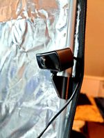
Creality ender enclosure webcam mount
...e creality enclosure. sure is better than a tripod. change it up if it helps. i printed pla with 50% infill on my dd ender 3 pro.
3d_export
free
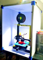
ender 3 enclosure corners
...er corners and 4 upper corners, using 25mmx25mm angled aluminium pieces that gets covered on inside of the frame with plexiglass
3d_export
free
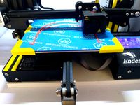
ender 3 3d print bed clips
...ed + normal aluminium bed frame of the creality ender 3 = 6mm (b) these clips are designed for glass plate + aluminium bed = 4mm
3d_export
$5
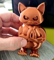
GRUMPY CAT
...grumpy cat 3dexport grumpy cat to print in ender ...
3d_export
$5

Logs fire
...with one multi material for corona and vray r ender. albedo, normal, uvmap, roughness format jpg 4096x4096 models:...
3d_export
$42

excavator
...is the original size. 0.12 mm printing surface creality ender5 ...
Mod
design_connected
$13

MOD. 4233 - MOD. 4234 Table Lamp
...mod. 4233 - mod. 4234 table lamp
designconnected
arcahorn mod. 4233 - mod. 4234 table lamp computer generated 3d model.
design_connected
$11

MOD.1095
...mod.1095
designconnected
mod.1095 computer generated 3d model. designed by sarfatti, gino.
3ddd
$1

fireplaces mod Spec
...fireplaces mod spec
3ddd
камин
fireplaces mod spec 180x90x125h
3ddd
free

Flos Mod. 2129
... mod
фабрика: flos
модель: mod. 2129
описание: подвесной светильник, металл, белый, черный.
сайт: www.flos.com
turbosquid
$34

Mod Lamp.c4d
... available on turbo squid, the world's leading provider of digital 3d models for visualization, films, television, and games.
turbosquid
$32
MOD A 001
... available on turbo squid, the world's leading provider of digital 3d models for visualization, films, television, and games.
turbosquid
$29

Maars Mod
... available on turbo squid, the world's leading provider of digital 3d models for visualization, films, television, and games.
turbosquid
$15

Mod 70..
... available on turbo squid, the world's leading provider of digital 3d models for visualization, films, television, and games.
turbosquid
$10

MOD Sofa
... available on turbo squid, the world's leading provider of digital 3d models for visualization, films, television, and games.
turbosquid
$1

Mod-Lite
... available on turbo squid, the world's leading provider of digital 3d models for visualization, films, television, and games.
Rail
3d_ocean
$5
rails
...rails
3docean
old rails rails sleepers
old rails
archibase_planet
free
Rail
...chibase planet
rail railing handrail guard-rail
rail forged fence n310814 - 3d model (*.gsm+*.3ds) for exterior 3d visualization.
archibase_planet
free

Rail
...rail
archibase planet
handrail railing guard-rail
rail n220914 - 3d model (*.gsm+*.3ds) for interior 3d visualization.
archibase_planet
free

Rail
...rail
archibase planet
railing hand-rail banisters
rail n130309 - 3d model (*.gsm+*.3ds) for interior 3d visualization.
archibase_planet
free
Rail
...rail
archibase planet
railing hand-rail banisters
rail n270510 - 3d model (*.gsm+*.3ds) for interior 3d visualization.
archibase_planet
free
Railing
...
archibase planet
railing handrail fence guard-rail
railing n140314 - 3d model (*.gsm+*.3ds+*.max) for exterior 3d visualization.
archibase_planet
free
Railing
...railing
archibase planet
railing
railing- 3d model (*.gsm+*.3ds) for interior 3d visualization.
archibase_planet
free
Railing
...railing
archibase planet
railing enclosure barrier
light railing - 3d model for interior 3d visualization.
archibase_planet
free
Rail
...rail
archibase planet
metal railing
rail n280608 - 3d model (*.gsm+*.3ds) for interior 3d visualization.
archibase_planet
free

Railing
...railing
archibase planet
railing kitchen ware
railing 1 - 3d model (*.gsm+*.3ds) for interior 3d visualization.
Axis
3ddd
$1

Мария Axis
...
3ddd
кухня , классическая , axis
модель кухни.
3d_export
$22
Axis robot 6-axis robotic arm
...ing parts drawings, standard parts purchased parts list, can be produced directly according to the drawings, welcome to download!
3ddd
free

Versatile Axis
...ddd
nexus , плитка
http://bvtileandstone.com/ceramic-porcelain/versatile-axis/
3d_export
$19
robot 2 axis
...robot 2 axis
3dexport
robot 2 axis
turbosquid
$40

Axis R5F
... available on turbo squid, the world's leading provider of digital 3d models for visualization, films, television, and games.
turbosquid
$40

Axis S5F
... available on turbo squid, the world's leading provider of digital 3d models for visualization, films, television, and games.
turbosquid
$30

Axis Athlon
... available on turbo squid, the world's leading provider of digital 3d models for visualization, films, television, and games.
turbosquid
$10
Linear Axis
... available on turbo squid, the world's leading provider of digital 3d models for visualization, films, television, and games.
3d_export
$15

drawing axis
...drawing axis
3dexport
simple rendering of the scene file
3ddd
$1
versatile axis ARC
...versatile axis arc
3ddd
versatile , плитка
versatile axis arc red dot design award
Z
3d_export
$5
nissan z
...nissan z
3dexport
nissan z
3ddd
$1

Vase Z
...vase z
3ddd
vase z
3ddd
$1
полотенцесушить Z
...полотенцесушить z
3ddd
полотенцесушитель
полотенцесушить z
design_connected
free

Z-Chair
...z-chair
designconnected
free 3d model of z-chair designed by karman, aleksei.
design_connected
$11

Z Lamp
...z lamp
designconnected
phillips z lamp computer generated 3d model. designed by kalff, louis.
3d_export
$5
Dragon balls z
...dragon balls z
3dexport
dragon ball z
turbosquid
$20

Fighter Z
...
turbosquid
royalty free 3d model fighter z for download as on turbosquid: 3d models for games, architecture, videos. (1292563)
turbosquid
$9

Pen Z
...pen z
turbosquid
free 3d model pen z for download as obj on turbosquid: 3d models for games, architecture, videos. (1686775)
turbosquid
free

z chair
...z chair
turbosquid
free 3d model z chair for download as max on turbosquid: 3d models for games, architecture, videos. (1410230)
turbosquid
$5

Letter Z
...urbosquid
royalty free 3d model letter z for download as max on turbosquid: 3d models for games, architecture, videos. (1408540)
3
turbosquid
$10

Mountain Bike 3 -3 of 3
...model mountain bike 3 (#3 of 3) for download as fbx and blend on turbosquid: 3d models for games, architecture, videos. (1438752)
turbosquid
$6

Rock 3-3
...urbosquid
royalty free 3d model rock 3-3 for download as obj on turbosquid: 3d models for games, architecture, videos. (1628065)
turbosquid
$29

Books 150 pieces 3-3-3
...books 150 pieces 3-3-3 for download as max, obj, fbx, and stl on turbosquid: 3d models for games, architecture, videos. (1384033)
turbosquid
$3

Genesis 3 Clothing 3
... available on turbo squid, the world's leading provider of digital 3d models for visualization, films, television, and games.
3d_export
$5
hinge 3
...hinge 3
3dexport
hinge 3
3ddd
$1
Розетка 3
...розетка 3
3ddd
розетка
розетка 3
turbosquid
$50

is-3
... available on turbo squid, the world's leading provider of digital 3d models for visualization, films, television, and games.
turbosquid
$10

Mountain Bike 3 -2 of 3
...model mountain bike 3 (#2 of 3) for download as fbx and blend on turbosquid: 3d models for games, architecture, videos. (1438750)
turbosquid
$10

Mountain Bike 1 -3 of 3
...model mountain bike 1 (#3 of 3) for download as fbx and blend on turbosquid: 3d models for games, architecture, videos. (1438743)
3d_export
$5

3 CATS
...3 cats
3dexport
3 cats pen holder