Thingiverse
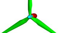
Lenz2 Helical Turbine XL by databeestje
by Thingiverse
Last crawled date: 2 years, 11 months ago
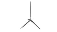
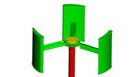
This is a larger version of the Lenz2 Helical turbine I started with to see what size I can get out of my Mendel 90 reliably. It is based on my earlier work in thing http://www.thingiverse.com/thing:87819
Update 2020-02-10
There are a fewq requests for older bits and I've decided to just link to the related Google Drive folder. See if you can find it.https://drive.google.com/drive/folders/0B0wheAwr-dLxMGtvNGRocEhBU2s?usp=sharing
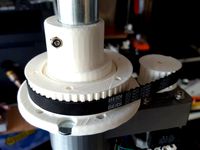
2018-06-22: Updated the OpenScad, and it should actually fit together without issue. Currently I'm not using the LG drive unit yet but a Hobbyking 53kV 4008 Gimbal motor (~25$) with a 17T pulley and a 112T pulley on the axle. That is good for a 5.8:1 ratio and at 150rpm that is good for ~38 volts open circuit. It is enough to trigger the Chinese grid-tie 22-60V inverter. A Hobbyking 6508 (30kV) Gimbal motor should be arriving soon which should make the motor pulley a bit easier to size. The current T5 belt is a T5-600-10, which is a bit short, a 690 is on order.
I did try to model the Lenz2 blade in Openscad but it is a bit heavy, so commented out. I need to do this with a proper OpenScad module which needs a bit more research. Alternatively I could just import a rendered STL of the blade.
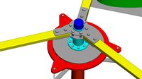
2018-06-12: Redesigned most of the rotating parts of the turbine into OpenScad. Took far less time then I thought, but not trivial. This is once more for the LG direct drive washing machine motor. And with the design now in OpenScad format it's far easier to adapt.
Ideally you should use a 6006 bearing with a 30mm ID and 55mm OD. But I had a 6806 lying which is not well suited but will do for testing. I have not printed any of the parts yet as I came to find out that Autodesk has ruined another great product (Netfabb basic) and removed the ruler to take dimensions. There are old versions on the net, but this is just silly.
The design is cheaper to make as the bearings are cheaper and standard size, the axle is plain central heating tube (7 euro per 2m) and less material in general.
2015-06-09: Uploaded the entire turbine again, if you need any of the old parts you need to contact me manually. This one has all the correct dimensions now as well as some updated designs for the NEMA mount and other fine adjustments.
I've also uploaded a video from one of the first test with the NEMA17 stepper, this was the wrong model, they came from eBay unstickered.
2014-09-23: I've gone back and checked on the dimensions of the blade here and it's woefully off. I've used the inner diameter instead of the outer diameter of the windmill giving a far too small blade. The actuall outer diameter is 45cm across, not the 32 I once thought. Oh well. I've redone the blade but need to verify it's ok before I upload that. https://www.youtube.com/watch?v=KUVS09pbNOk
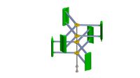
I've decided to go to a 24 degree rotation per layer so you can now make it 5 layers high which is a 60% increase in swept area. That coupled with +20% extra swept area from the correct blade size (66mm vs 84mm J cup) should make a lot off difference.
I've found out that 2 meters of M16 threaded rod is readily available which made me go to 5 layers. that would give 5x20cm, or 5x30cm on a larger 3D printer. For now I'll just make 3 layers for testing until I aquire a longer threaded rod.
I've found a tool for proper blade design in the form of EasyCFD, but it's a 180 euros. So that's a bit steep for a personal investment. I've already poured in quite a bit of personal R&D money in this thing over the past year in small increments. But a once off purchase is just a bit steep.
That or I need to learn OpenFoam.
2014-09-08: I've uploaded a few new and updated pieces
Uploaded Center hub type D again incase I missed something.
Uploaded drilling guide for the square wooden pole, attempting thise mount soon. Drill small 4mm guide hole, then drill with long wood drill.
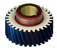
Added 2 spur gears I got from solidworks gears files for mounting on the new rotor hub.
Added newer rotor hub that has a few more holes for mounting the spur gear and has a clamp. If you have the clearance for it you could mount the spur on the bottom of the hub. A larger 100 tooth spur gear should follow.
2014-08-29: I've just uploaded another M16 rod NEMA17 motor mount, it is meant to be used in combination with a 68x68mm wooden pole. The idea being that you drill a 16mm hole 30cm deep into the center of the wooden pole where 30cm of the rod goes and the square motor mount sits on top. This further reduces the amount of parts involved, and this is a common size in europe for wooden poles.
The trick part is getting the deep hole straight and center, i'll upload a drilling guide shortly which should make it easier. If you have a good flat surface this becomes quite a bit easier. One drawback is that if you use a Hall proximity sensor like I do, you need to chamfer one edge of the top of the pole to make that fit, I will include that hole in the drilling guide regardless. If you don't need a RPM sensor then forget the chamfer.
2014-08-24: Added a couple of files with a new variation of the 28mm tube clamp which is a bit lighter on plastic and needs just 1 bolt/nut
Added a NEMA14 motor mount for use as a generator. I've come to the insight that the LG drive is just too heavy for such a small application. Using high rated voltage NEMA14 stepper motors might be a solution. One of the other options was a NEMA23 stepper with a 24Volt rated voltage. Might need to make the alternate mount in NEMA23 also.
Still need to make new drive hub for the NEMA motors using a MOD1 gear as a base, have not found any good ones yet. A lot of herringbone gears, but I need the tolerance of the straight MOD1 gears. Might be able to use MOD1 RC pinions for a 5mm shaft.
2014-08-22: Note for the international users, you should be able to replace the LG Direct Drive washing machine motor with a Fisher and Paykel smart drive which is very common in other parts of the world. You can also find a good de-cogging howto and what to watchout for on http://www.thebackshed.com/windmill/articles/decoggingFP.asp
2014-08-18: Please note that there is currently a KickStarter project featuring this wind turbine that is in no way affiliated with me, nor was permission asked for the use of the files! https://www.kickstarter.com/projects/43717383/airenergy-3d-a-3d-printed-opensource-mobile-wind-t
2014-01-09: Some hickups with the development work for the M20 threaded rod version. Some failed prints as well as wrong dimension and a spacer that got stuck in the Aluminium pipe didn't help.
The new roll of PLA I got from reprapworld appears to be handling different from the previous roll of white. Curse cheap PLA :)
Adjusted the stator mount with a 12mm hole for the proximity NPN sensor from eBay.
Adjusted the rotor mount with a flange to keep rain away from the bearing and a spot to mount the magnet for the proximity sensor.
The threaded rod is 1 meter, the 28mm central heating pipe axle is 65cm. You need 70cm of rod measured from above the nut from the stator mount so that you can fit the axle and still use a Nyloc nut on top.
Needs a new cone for the top that clears the larger M20 Nyloc nut.
Decogging the stator with a new Dremel bit works a lot better, finished soon.
The bottom bearing is a 42x20x12mm.
The top bearing is a 37x20x11mm
Simplified the center hub mount with just a single clamp notch instead of 3.
I'll upload the updated files soon, they are not so wildly different from the existing ones though.
2013-11-11: I'm currently designing a few new parts around M20 threaded rod to replace the M10 threaded rod. The reason being that the M10 is just too thin for the shaft. The good part is that it bends before it breaks. The 8.8 strength of the threaded rod is providing enough "springy" tension to stay straight.
I've looked at M16, which easy to measure into the design, but bearings for that diameter is a pain and are relatively pricey (10 euros a piece, vs 4). The closest thing would be american 5/8" bearings, but at 15.8mm that could be a problem.
The basic construction of the windmill doesn't really change at all. Sure, I need to accomodate for the larger 20x42x12mm bearings but that's hardly something to hold against it. Contemplating how to clamp the bearing down inside the 28mm axle.
I've found a few M20 smooth rod end couplings, sawed them in half and had a friend use the lathe to bring the diameter down to 23,5mm. It might not really be necessary in the end though. I'll see if I can edit a construction guide for the M20 version.
I've got a Tachometer form eBay with sensor, as well as a Raspberry Pi to collect data. Tried decogging the stator on the bench grinder, didn't like the result. Trying the dremel next.
2013-10-29: It made it through the storm pretty well considering the whole thing toppled over the fence. http://www.youtube.com/watch?v=hlad7XvNYXE
2013-10-28: Made another youtube video of the windmill in action in a autumn storm.http://www.youtube.com/watch?v=xqPAQ432y3s
2013-09-03: Uploaded the 190mm high, 320mm diameter blade model.
2013-08-01: More gallery and pictures posted.
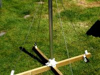
2013-07-08: All 9 blades are printed and I mounted everything up on a wooden pole in the backyard. It spins freely until I sort out the electrical parts.
Uploaded a video of it on YouTube https://www.youtube.com/watch?v=005ezJTRxqc
2013-07-07: Added spacers and a bearing 5 inchs above the lower bearing on the M10 rod using 10mm ID steel pipe. Tightening everything down with M10 nuts helps a lot for the strength of the axle. A lot less wobble now.
2013-06-29: Another blade printed, more gallery pictures, now with bearing cap on top. Finally starting to resemeble something.
2013-06-27: Some more assembly work, underestimated the amount of force required to rotate the windmill with the rotor in place. The construction of the LG direct drive motor prevents it from freely rotating due to the magnets pulling on the metal core of the stator. Need to evaluate the options here short of making my own stator and rotor.
Also been thining of making top and bottom winglet mounts for the wings. They save 7% fuel in the aircraft world, are they any use in wind mills? :-) They would basically consist of the first 20mm for the top and last 20mm for the bottom.
Uploaded update blade arm with a square piece for a nicer look and fit into the center hub.
Added top bearing holder for the 10x32x9 I had laying around. Needs a pretty endcap possibly for the top.
Top center hub clamp goes on upside down, the top bearing carrier fits on top of it, M4 screws tie them together with the blade arm.
Added initial rotor hub for the LG direct drive rotor, it fits well, but needs to be redone for my new bearing. I added a extra M10 nut on the bottom, put the 10x35x9 bearing on top, then tighten with another M10 nut on top to keep it in place. Still waiting for the 10x30x14 angular contact bearing. That means I also need to redo the bottom rotor hub possibly, the one I did now came out pretty poor, the supports didn't come off cleanly.
2013-06-26: Finally had the plastic to print the large LG stator mount. First assembly in pictures uploaded of the work in progress. Starting to resemble a shape now.
I use plenty of M4 hex cap screws with washers and nyloc nuts for clamping Axle guides.
The LG stator mount uses hex head bolts M8 with washers and Nyloc nuts. The nuts that fit inside the axle guide are M10, ofcourse.
Used 2 M5 hex cap screws with washers and nyloc nuts for clamping the stator mount to the pole.
Added 28mm OD clamp central hub for galvanized central heating pipe.-
Need to design bearing mounts for the 28mm pipe (axle). The rotor will also clamp to this pipe. The M10 rod is just for mounting.
Need to design rotor mount to fit the axle. Difficult to do without the bearings which are still in the post somewhere between here and there.
2013-06-23: Printed a few bearing hubs for my 10x32x9 bearings I had laying around so I could atleast mount them to get a feel for the size. Also printed a few of the arms to mount them. 2mm plastic is not strong enough for the weight, so the arm is now 3mmx20mm and the last part is 2mm thick to slot into the blades.
Added bearing holders for 22, 26 and 32mm OD bearings.
Removed the old 24cm diameter blade.
Add arm for 40mm center offset, 168mm from center to inner hole, +50mm for outer hole. Just fits on the 200x200 print bed.
2013-06-15: 1st blade succesfully printed, 2nd failed 2/3rd of the way in and it has a rather strange spot. Turns out the roll of PLA is very inconsistent causing printing issues. Added a gallery picture of the work so far.
Updated pretty much all designs:
Blade, moved middle bottom hole by 1 mm for a better fit. Requires 16,5m of filament, needs 9 hours to print at 30mm/s
Axle guide, increased thickness for the clamp part so that it has a more meaty clamp.
Surface mount, made the hole larger, it was too tight for the 48mm OD tube and required work on my part to get it to fit. Could also be related to the roll of PLA I am using for this. Added better clamp flanges too.
Top flange for mounting the LG stator, might change in the future but should fit the tube, has a axle guide for inside the tube. Probably over engineered, don't care as much. Not printed yet.
2013-06-13: Printed the bottom flange to mount the pole on a surface, added a gallery picture of it. Printing the 1st of 9 blades now. Working out the top flange for the stator mount.
Todo:
hub for the rotor
bearing mount for the rotor axle
hub with bearing mount for the blade arms
2013-06-11: Uploaded the surface mount flange for the 48mm OD 43mm ID Aluminium tube. You are meant to clamp the top using a hose clamp. Drill a hole near the bottom through the plastic and aluminium to feed the wire through.
2013-06-11: Uploaded the M10 thread rod guide I am using for spacing the axle inside the 48mm OD 43mm ID Aluminium tube I am using for the stator mount. Drill 2 holes for the clamp through the top wings so you can mount a screw and nut to tighten the clamp.
2013-06-09: Uploaded the 32cm diameter version which is the first that has a space where the arm needs to go. This should make for a better aerodynamic profile with the screws on the inside.
The new mounting means the (to be) 20x2mm aluminium arm slots into the blade(s) where it is mounted in between 2 blades with the cap screws. That should give a decently rigid structure. From the scale 1/2 model I printed, the holes line up pretty well. I can't see if I'm spot on until I print the full scale which will take hours to print.
Also: I'm running out of Faberdashery "Desert Tan".
2013-06-08: I've also remodeled a blade for a 32cm diameter (~12 inches) which is about the limit that you can make it. That requires a 190x190x190mm print envelope (8x8x8inch). That blade is not uploaded yet, because the alignment for the holes is not tested yet.
2013-06-07: Purchased a LG "Direct Drive" washing machine motor assembly so that I have something to drive with the turbine. Working out dimensions for a mount to put here later. Involves aluminium tube.
2013-06-06: I managed to print the entire blade for the 24cm diameter version with the fan off and it stayed attached to the printbed for the entire print which is satisfying. No warping with the fan off. The screw holes for the M4 bolts align well on this version.
2013-06-02: So far, the 1st attempt had pretty severe warping and I broke it off early on. hoping i can solve by just printing it on a raft.
Update 2020-02-10
There are a fewq requests for older bits and I've decided to just link to the related Google Drive folder. See if you can find it.https://drive.google.com/drive/folders/0B0wheAwr-dLxMGtvNGRocEhBU2s?usp=sharing
2018-06-22: Updated the OpenScad, and it should actually fit together without issue. Currently I'm not using the LG drive unit yet but a Hobbyking 53kV 4008 Gimbal motor (~25$) with a 17T pulley and a 112T pulley on the axle. That is good for a 5.8:1 ratio and at 150rpm that is good for ~38 volts open circuit. It is enough to trigger the Chinese grid-tie 22-60V inverter. A Hobbyking 6508 (30kV) Gimbal motor should be arriving soon which should make the motor pulley a bit easier to size. The current T5 belt is a T5-600-10, which is a bit short, a 690 is on order.
I did try to model the Lenz2 blade in Openscad but it is a bit heavy, so commented out. I need to do this with a proper OpenScad module which needs a bit more research. Alternatively I could just import a rendered STL of the blade.
2018-06-12: Redesigned most of the rotating parts of the turbine into OpenScad. Took far less time then I thought, but not trivial. This is once more for the LG direct drive washing machine motor. And with the design now in OpenScad format it's far easier to adapt.
Ideally you should use a 6006 bearing with a 30mm ID and 55mm OD. But I had a 6806 lying which is not well suited but will do for testing. I have not printed any of the parts yet as I came to find out that Autodesk has ruined another great product (Netfabb basic) and removed the ruler to take dimensions. There are old versions on the net, but this is just silly.
The design is cheaper to make as the bearings are cheaper and standard size, the axle is plain central heating tube (7 euro per 2m) and less material in general.
2015-06-09: Uploaded the entire turbine again, if you need any of the old parts you need to contact me manually. This one has all the correct dimensions now as well as some updated designs for the NEMA mount and other fine adjustments.
I've also uploaded a video from one of the first test with the NEMA17 stepper, this was the wrong model, they came from eBay unstickered.
2014-09-23: I've gone back and checked on the dimensions of the blade here and it's woefully off. I've used the inner diameter instead of the outer diameter of the windmill giving a far too small blade. The actuall outer diameter is 45cm across, not the 32 I once thought. Oh well. I've redone the blade but need to verify it's ok before I upload that. https://www.youtube.com/watch?v=KUVS09pbNOk
I've decided to go to a 24 degree rotation per layer so you can now make it 5 layers high which is a 60% increase in swept area. That coupled with +20% extra swept area from the correct blade size (66mm vs 84mm J cup) should make a lot off difference.
I've found out that 2 meters of M16 threaded rod is readily available which made me go to 5 layers. that would give 5x20cm, or 5x30cm on a larger 3D printer. For now I'll just make 3 layers for testing until I aquire a longer threaded rod.
I've found a tool for proper blade design in the form of EasyCFD, but it's a 180 euros. So that's a bit steep for a personal investment. I've already poured in quite a bit of personal R&D money in this thing over the past year in small increments. But a once off purchase is just a bit steep.
That or I need to learn OpenFoam.
2014-09-08: I've uploaded a few new and updated pieces
Uploaded Center hub type D again incase I missed something.
Uploaded drilling guide for the square wooden pole, attempting thise mount soon. Drill small 4mm guide hole, then drill with long wood drill.
Added 2 spur gears I got from solidworks gears files for mounting on the new rotor hub.
Added newer rotor hub that has a few more holes for mounting the spur gear and has a clamp. If you have the clearance for it you could mount the spur on the bottom of the hub. A larger 100 tooth spur gear should follow.
2014-08-29: I've just uploaded another M16 rod NEMA17 motor mount, it is meant to be used in combination with a 68x68mm wooden pole. The idea being that you drill a 16mm hole 30cm deep into the center of the wooden pole where 30cm of the rod goes and the square motor mount sits on top. This further reduces the amount of parts involved, and this is a common size in europe for wooden poles.
The trick part is getting the deep hole straight and center, i'll upload a drilling guide shortly which should make it easier. If you have a good flat surface this becomes quite a bit easier. One drawback is that if you use a Hall proximity sensor like I do, you need to chamfer one edge of the top of the pole to make that fit, I will include that hole in the drilling guide regardless. If you don't need a RPM sensor then forget the chamfer.
2014-08-24: Added a couple of files with a new variation of the 28mm tube clamp which is a bit lighter on plastic and needs just 1 bolt/nut
Added a NEMA14 motor mount for use as a generator. I've come to the insight that the LG drive is just too heavy for such a small application. Using high rated voltage NEMA14 stepper motors might be a solution. One of the other options was a NEMA23 stepper with a 24Volt rated voltage. Might need to make the alternate mount in NEMA23 also.
Still need to make new drive hub for the NEMA motors using a MOD1 gear as a base, have not found any good ones yet. A lot of herringbone gears, but I need the tolerance of the straight MOD1 gears. Might be able to use MOD1 RC pinions for a 5mm shaft.
2014-08-22: Note for the international users, you should be able to replace the LG Direct Drive washing machine motor with a Fisher and Paykel smart drive which is very common in other parts of the world. You can also find a good de-cogging howto and what to watchout for on http://www.thebackshed.com/windmill/articles/decoggingFP.asp
2014-08-18: Please note that there is currently a KickStarter project featuring this wind turbine that is in no way affiliated with me, nor was permission asked for the use of the files! https://www.kickstarter.com/projects/43717383/airenergy-3d-a-3d-printed-opensource-mobile-wind-t
2014-01-09: Some hickups with the development work for the M20 threaded rod version. Some failed prints as well as wrong dimension and a spacer that got stuck in the Aluminium pipe didn't help.
The new roll of PLA I got from reprapworld appears to be handling different from the previous roll of white. Curse cheap PLA :)
Adjusted the stator mount with a 12mm hole for the proximity NPN sensor from eBay.
Adjusted the rotor mount with a flange to keep rain away from the bearing and a spot to mount the magnet for the proximity sensor.
The threaded rod is 1 meter, the 28mm central heating pipe axle is 65cm. You need 70cm of rod measured from above the nut from the stator mount so that you can fit the axle and still use a Nyloc nut on top.
Needs a new cone for the top that clears the larger M20 Nyloc nut.
Decogging the stator with a new Dremel bit works a lot better, finished soon.
The bottom bearing is a 42x20x12mm.
The top bearing is a 37x20x11mm
Simplified the center hub mount with just a single clamp notch instead of 3.
I'll upload the updated files soon, they are not so wildly different from the existing ones though.
2013-11-11: I'm currently designing a few new parts around M20 threaded rod to replace the M10 threaded rod. The reason being that the M10 is just too thin for the shaft. The good part is that it bends before it breaks. The 8.8 strength of the threaded rod is providing enough "springy" tension to stay straight.
I've looked at M16, which easy to measure into the design, but bearings for that diameter is a pain and are relatively pricey (10 euros a piece, vs 4). The closest thing would be american 5/8" bearings, but at 15.8mm that could be a problem.
The basic construction of the windmill doesn't really change at all. Sure, I need to accomodate for the larger 20x42x12mm bearings but that's hardly something to hold against it. Contemplating how to clamp the bearing down inside the 28mm axle.
I've found a few M20 smooth rod end couplings, sawed them in half and had a friend use the lathe to bring the diameter down to 23,5mm. It might not really be necessary in the end though. I'll see if I can edit a construction guide for the M20 version.
I've got a Tachometer form eBay with sensor, as well as a Raspberry Pi to collect data. Tried decogging the stator on the bench grinder, didn't like the result. Trying the dremel next.
2013-10-29: It made it through the storm pretty well considering the whole thing toppled over the fence. http://www.youtube.com/watch?v=hlad7XvNYXE
2013-10-28: Made another youtube video of the windmill in action in a autumn storm.http://www.youtube.com/watch?v=xqPAQ432y3s
2013-09-03: Uploaded the 190mm high, 320mm diameter blade model.
2013-08-01: More gallery and pictures posted.
2013-07-08: All 9 blades are printed and I mounted everything up on a wooden pole in the backyard. It spins freely until I sort out the electrical parts.
Uploaded a video of it on YouTube https://www.youtube.com/watch?v=005ezJTRxqc
2013-07-07: Added spacers and a bearing 5 inchs above the lower bearing on the M10 rod using 10mm ID steel pipe. Tightening everything down with M10 nuts helps a lot for the strength of the axle. A lot less wobble now.
2013-06-29: Another blade printed, more gallery pictures, now with bearing cap on top. Finally starting to resemeble something.
2013-06-27: Some more assembly work, underestimated the amount of force required to rotate the windmill with the rotor in place. The construction of the LG direct drive motor prevents it from freely rotating due to the magnets pulling on the metal core of the stator. Need to evaluate the options here short of making my own stator and rotor.
Also been thining of making top and bottom winglet mounts for the wings. They save 7% fuel in the aircraft world, are they any use in wind mills? :-) They would basically consist of the first 20mm for the top and last 20mm for the bottom.
Uploaded update blade arm with a square piece for a nicer look and fit into the center hub.
Added top bearing holder for the 10x32x9 I had laying around. Needs a pretty endcap possibly for the top.
Top center hub clamp goes on upside down, the top bearing carrier fits on top of it, M4 screws tie them together with the blade arm.
Added initial rotor hub for the LG direct drive rotor, it fits well, but needs to be redone for my new bearing. I added a extra M10 nut on the bottom, put the 10x35x9 bearing on top, then tighten with another M10 nut on top to keep it in place. Still waiting for the 10x30x14 angular contact bearing. That means I also need to redo the bottom rotor hub possibly, the one I did now came out pretty poor, the supports didn't come off cleanly.
2013-06-26: Finally had the plastic to print the large LG stator mount. First assembly in pictures uploaded of the work in progress. Starting to resemble a shape now.
I use plenty of M4 hex cap screws with washers and nyloc nuts for clamping Axle guides.
The LG stator mount uses hex head bolts M8 with washers and Nyloc nuts. The nuts that fit inside the axle guide are M10, ofcourse.
Used 2 M5 hex cap screws with washers and nyloc nuts for clamping the stator mount to the pole.
Added 28mm OD clamp central hub for galvanized central heating pipe.-
Need to design bearing mounts for the 28mm pipe (axle). The rotor will also clamp to this pipe. The M10 rod is just for mounting.
Need to design rotor mount to fit the axle. Difficult to do without the bearings which are still in the post somewhere between here and there.
2013-06-23: Printed a few bearing hubs for my 10x32x9 bearings I had laying around so I could atleast mount them to get a feel for the size. Also printed a few of the arms to mount them. 2mm plastic is not strong enough for the weight, so the arm is now 3mmx20mm and the last part is 2mm thick to slot into the blades.
Added bearing holders for 22, 26 and 32mm OD bearings.
Removed the old 24cm diameter blade.
Add arm for 40mm center offset, 168mm from center to inner hole, +50mm for outer hole. Just fits on the 200x200 print bed.
2013-06-15: 1st blade succesfully printed, 2nd failed 2/3rd of the way in and it has a rather strange spot. Turns out the roll of PLA is very inconsistent causing printing issues. Added a gallery picture of the work so far.
Updated pretty much all designs:
Blade, moved middle bottom hole by 1 mm for a better fit. Requires 16,5m of filament, needs 9 hours to print at 30mm/s
Axle guide, increased thickness for the clamp part so that it has a more meaty clamp.
Surface mount, made the hole larger, it was too tight for the 48mm OD tube and required work on my part to get it to fit. Could also be related to the roll of PLA I am using for this. Added better clamp flanges too.
Top flange for mounting the LG stator, might change in the future but should fit the tube, has a axle guide for inside the tube. Probably over engineered, don't care as much. Not printed yet.
2013-06-13: Printed the bottom flange to mount the pole on a surface, added a gallery picture of it. Printing the 1st of 9 blades now. Working out the top flange for the stator mount.
Todo:
hub for the rotor
bearing mount for the rotor axle
hub with bearing mount for the blade arms
2013-06-11: Uploaded the surface mount flange for the 48mm OD 43mm ID Aluminium tube. You are meant to clamp the top using a hose clamp. Drill a hole near the bottom through the plastic and aluminium to feed the wire through.
2013-06-11: Uploaded the M10 thread rod guide I am using for spacing the axle inside the 48mm OD 43mm ID Aluminium tube I am using for the stator mount. Drill 2 holes for the clamp through the top wings so you can mount a screw and nut to tighten the clamp.
2013-06-09: Uploaded the 32cm diameter version which is the first that has a space where the arm needs to go. This should make for a better aerodynamic profile with the screws on the inside.
The new mounting means the (to be) 20x2mm aluminium arm slots into the blade(s) where it is mounted in between 2 blades with the cap screws. That should give a decently rigid structure. From the scale 1/2 model I printed, the holes line up pretty well. I can't see if I'm spot on until I print the full scale which will take hours to print.
Also: I'm running out of Faberdashery "Desert Tan".
2013-06-08: I've also remodeled a blade for a 32cm diameter (~12 inches) which is about the limit that you can make it. That requires a 190x190x190mm print envelope (8x8x8inch). That blade is not uploaded yet, because the alignment for the holes is not tested yet.
2013-06-07: Purchased a LG "Direct Drive" washing machine motor assembly so that I have something to drive with the turbine. Working out dimensions for a mount to put here later. Involves aluminium tube.
2013-06-06: I managed to print the entire blade for the 24cm diameter version with the fan off and it stayed attached to the printbed for the entire print which is satisfying. No warping with the fan off. The screw holes for the M4 bolts align well on this version.
2013-06-02: So far, the 1st attempt had pretty severe warping and I broke it off early on. hoping i can solve by just printing it on a raft.
Similar models
grabcad
free

Hub motor brushless
...hub motor brushless
grabcad
this is a brushless hub motor that consists of blade, coil, stator, motor shell, rod
grabcad
free

Grin All axle motor stator guide
...eassembly. you will also need a 20mm hollow pipe which goes through the center hole and guides the stator towards the side plate.
grabcad
free

Brushless hub motor parts
...brushless hub motor parts
grabcad
motor shell, stator, copper coil, circlip, blade rod
thingiverse
free
Drag Knife for MPCNC universal mount by FarFlyer
...again. if you find something wrong, let me know.
i plan to design a blade cover in order to be on the safe side when i have time.
thingiverse
free
Windmill With Tail by cratch
...sure the tail rod pushed in easily. superglue or similar to all push in joints. i assembled the windmill...
thingiverse
free

Mounting Hub for 3mm D-shaft motor and 16 tooth LEGO gear (Short Version) by kbuckley
... by the motor after a few hours of driving.
i've also attached the inventor file if you need to change make the hub longer.
thingiverse
free

8 Port Mechanical Siren by Vonel
...i plan to include a housing and a motor mount. rotor and stator should be finished. i will upload different port ratios later on.
grabcad
free

Sunnysky V3508 Brushless Motor
... of the assembly which has individual wires visible in the stator and a low res version which has a block of copper as the wires.
grabcad
free

Bicycle Front Hub
... with numbers 62200, 4200,3200 can be inserted according to your driving requirements. i will upload axle of this hub separately.
thingiverse
free
Clamp for 12mm linear rail compression type by RickyW
...yringe in the area pressed on by the nut when tightened to help bond the layers better and don't over tighten the pinch bolt.
Lenz2
thingiverse
free

Lenz2 airfoil for a turbine by pandakaas
...lenz2 airfoil for a turbine by pandakaas
thingiverse
model of the lenz2 airfoil.
thingiverse
free

Lenz2 helical turbine by databeestje
...hat is a issue with the stl importer for sketchup.
these stl files are hole free and should go through slic3r without warnings.
thingiverse
free

Wind generator Lenz II turbine by andreykyz
...by andreykyz thingiverse wind generator lenz ii turbine acording byhttp://www.windstuffnow.com/main/lenz2turbine.htmhttp://www.instructables.com/id/lenz2-wind-turbine/?allsteps ...
thingiverse
free
Mast mount for 48mm OD Aluminium pipe by databeestje
...thingiverse i needed a mobile mast mount for my lenz2 helical xl from thing 99132 so i made some...
thingiverse
free
OpenSCAD Parametric Pulleys with mount holes derivative from 16627 by databeestje
...specific option for a pulley from my thing 99132 lenz2 helical xl. also added the option to have the...
thingiverse
free

Vertical Wind turbine and 3Phase alternator 9 Coils / 12 magnets by iZe
...on the field!) this design is inspired to the "lenz2 helical turbine xl", i plan to use the wind...
grabcad
free

Lenz2 VAWT
...e of vertical axis wind turbine i made for school project. nothing special, but it might help someone to get the concept of vawts
grabcad
free

Wind turbine type lenz2
...wind turbine type lenz2.
axial flux generator for direct-drive wind turbines.
https://www.windstuffnow.com/main/lenz2_turbine.htm
grabcad
free

Small Lenz2 turbine 3D printable
...e 3d printable
grabcad
small wind turbine of the lenz2 type.
parts optimized for 3d printing.
suitable for educational purposes.
Databeestje
thingiverse
free

Parametric Phone Holder by databeestje
...metric phone holder by databeestje
thingiverse
should be easy to print and modify for various phone sizes with or without cases.
thingiverse
free
Generic configurable PCB mount by databeestje
... wanted something fancier then just the seperate tubes.
so i connected them up, and you can configure the sizes in the scad file.
thingiverse
free

Weather Proof cable box by databeestje
...or even fits. i have not printed it yet.
supposedly a rubber band should be wrapped around the face to make a water tight seal.
thingiverse
free
RC 17mm Hex wheel nut wrench by databeestje
... nut wrench by databeestje
thingiverse
i was in need of a 17mm hex wheel nut wrench for my new 1/8th scale.
a wrench was born!
thingiverse
free
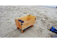
Bolderkar by databeestje
...aal af, maar het werkt allemaal goed genoeg, en met 90cm lang kan deze precies overdwars, opgevouwen in de kofferbak van de auto.
thingiverse
free

Gutter drain leaf guard by databeestje
...hat needs better sizing for a side vent.
openscad, so relatively easy to adjust, although i didn't make anything variables :)
thingiverse
free

18650 holder configurable by databeestje
...e cells from there.
you can configure half open or not with a true/false. it only makes sense on the 2 by x configuration though.
thingiverse
free

Clip on desk cable guide by databeestje
... 1 of the desks whilst sliding the other way for routing wires. also made a single desk clip but have not tried that variant yet.
thingiverse
free

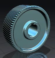
Mendel90 large Herringbone gear by databeestje
...90.
in the picture the original gear is left, the new one for the mendel90 is on the right, just forget that one in the middle.
thingiverse
free

Lithium Maintenance Charger by databeestje
..., depending on which way you want to mount the charger boards. a fan with duct might be a solution in the longitudinal direction.
Helical
3d_export
$5
helical gear
...helical gear
3dexport
helical gear
3d_export
$5
Helical Gear
...l contact ratio which can improve vibration and noise. badly designed helical gears can be noisier than well designed spur gears.
turbosquid
$5
Helical Gear
...squid
royalty free 3d model helical gear for download as stl on turbosquid: 3d models for games, architecture, videos. (1502723)
turbosquid
$4

helical gears
...id
royalty free 3d model helical gears for download as blend on turbosquid: 3d models for games, architecture, videos. (1423917)
turbosquid
$40

Helical Stairs
...el helical stairs for download as 3ds, max, ige, obj, and fbx on turbosquid: 3d models for games, architecture, videos. (1422987)
turbosquid
$32

armchair-Helical
... available on turbo squid, the world's leading provider of digital 3d models for visualization, films, television, and games.
turbosquid
$20

helical gear
... available on turbo squid, the world's leading provider of digital 3d models for visualization, films, television, and games.
turbosquid
$10

helical gear
...cal gear for download as max, unitypackage, 3ds, fbx, and obj on turbosquid: 3d models for games, architecture, videos. (1667275)
turbosquid
$4

Helical gear
... gear for download as sldpr, 3dm, 3ds, fbx, ige, obj, and stl on turbosquid: 3d models for games, architecture, videos. (1530622)
3d_export
$50

HELICAL BEVEL GEAR
...lel and perpendicular. in parallel-axis helical gears the two opposite-hand gears provide quiet operation and high load capacity.
Xl
turbosquid
$33

Nokia XL and XL Dual Orange
... available on turbo squid, the world's leading provider of digital 3d models for visualization, films, television, and games.
turbosquid
$29

Nokia XL and XL Dual Yellow
... available on turbo squid, the world's leading provider of digital 3d models for visualization, films, television, and games.
turbosquid
$29

Nokia XL and XL Dual Cyan
... available on turbo squid, the world's leading provider of digital 3d models for visualization, films, television, and games.
turbosquid
$29

Nokia XL and XL Dual Black
... available on turbo squid, the world's leading provider of digital 3d models for visualization, films, television, and games.
design_connected
$13

Diana XL
...diana xl
designconnected
delightfull diana xl computer generated 3d model.
3ddd
$1

модель XL
...модель xl
3ddd
sklo+glas , дверь
стеклянные двери фирмы sklo+glas , модель xl
turbosquid
$69

Nokia XL and XL Dual All Color
... available on turbo squid, the world's leading provider of digital 3d models for visualization, films, television, and games.
turbosquid
$33

Nokia XL and XL Dual Bright Green
... available on turbo squid, the world's leading provider of digital 3d models for visualization, films, television, and games.
3ddd
$1

Oslo XL LB
...oslo xl lb
3ddd
камин , oslo
камин oslo xl lb
3ddd
$1

BAY XL
... giulio marelli
giulio marelli italia. bay xl.
диван, дизайн studio crgm в тканевом исполнении.
длина: 2.55
Turbine
3d_export
$5

turbine
...turbine
3dexport
it is a turbine to use it in some spaceship
3d_export
$5

turbine
...turbine
3dexport
turbine, with animation included, more texture of it
3d_ocean
$4

Wind Turbine
...n
and render setup turbine wind
wind turbine, modeled with cinema4d r13 , render setup and textured, custom logo for wind turbine
turbosquid
$1

Turbine
...turbosquid
royalty free 3d model turbine for download as ige on turbosquid: 3d models for games, architecture, videos. (1385242)
3d_export
$40
wind turbine
...wind turbine
3dexport
wind turbine
3d_export
$40

wind turbine
...wind turbine
3dexport
wind turbine
3d_export
$40
wind turbine
...wind turbine
3dexport
wind turbine
3d_export
$40
wind turbine
...wind turbine
3dexport
wind turbine
3d_export
$40
wind turbine
...wind turbine
3dexport
wind turbine
3d_export
$40
wind turbine
...wind turbine
3dexport
wind turbine