Thingiverse
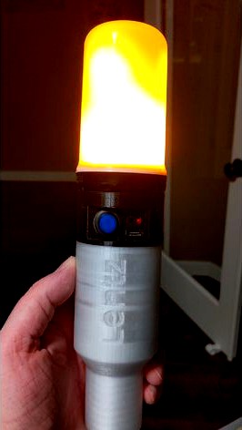
LED Tiki Torch by darthmuffin
by Thingiverse
Last crawled date: 3 years, 3 months ago
General:
PETG required, at least for the upper, as I saw the charge controller chip get to at least 170F during testing. Tolerance on printed parts accounts for a 0.40 nozzle. I printed with 0.30 layers bottom, 0.20 layers top, 4 perimiters and 15% infill using a 0.40 nozzle on a Prusa Mk3. Lower is Atomic Glow PETG (discontinued) and upper is Atomic CF PETG. I used supports for upper and lower, but especially the lower you might not need it if your briding is tuned well.
The flat portion on the lower section is for a name tag, or if you're fancy edit in an embossed name. For my use I see them left out in group camping areas, etc. and I wanted to make sure they come home.
Environmental Notes:
This is not water resistant without the cap. The stock globe has a vent on the top and there are vents in the model to aid the convection cooling. Is it really needed, especially with the converter gone? Dunno so the optional rain cap comes with the caveat of possibly shortening diode lifespan through overheating. Cap has a reinforced center in case you want to screw in an eyelet to tether it.
Parts:
LED flame light: https://www.amazon.com/gp/product/B07Q1CJJN1 (the version with the black base)
Charge controller board: https://www.amazon.com/gp/product/B07PKND8KG
A 16mm push on/off switch. I used a blue version of this because it's what I had on hand. https://www.amazon.com/Aexit-Switches-Self-Locking-Indicator-Pushbutton/dp/B07L6B4K6H I didn't hook up the indicator light in the switch.
Four 18650 batteries, matched as far as capacity, age, and state of charge. Power use is 220-250ma depending on mode. 4 x 3400mAh batteries would give 56hrs runtime. The cheapest 1000mAh cells you can find would still give 16hrs.
Two 3mm LEDs, different colors (red/blue are the stock colors)
Three 3mm x 12-15ish mm machine screws and washers
Three 3mm hex nuts
Wire. I used 24ga silicone sheath.
4 scraps of any type of 1.75mm filament, 12-13mm long
3/4" SCH-40 PVC pipe for the support shaft (tip, if budget allows look for "furniture grade" for better looking, stronger, UV resistant, and colors).
A stake or length of rebar to pound in the ground and slide the PVC over.
CA glue
optional: RTV silicone sealant and hot glue
Disassembly of stock flame light:
Use a spudger or similar to pry the white globe off. It's held on by a spot of glue on opposite sides.
Grab the edison bulb base with a big pair of pliers and pull/twist it off, you'll probably bend the base making this irreversible.
Cut the wires between the converter board and the edison base.
Feed the converter board up the tube and cut the wires at it which go to the LED circuit board. You won't need the converter.
Cut off the black base to give yourself a little more mounting room (see pictures). A dremel with cutoff wheel worked well.
Batteries:
Wire the four in parallel. Joining two pairs with hot glue then joining the pairs before soldering worked for me. Kaptan tape is optional but a good idea. A small wire connecting the cells is fine, they will see a max of 1A charge and 250ma discharge (collectively). Check youtube for tutorials on soldering to batteries--a light sanding, solder flux, pre-tinning both parts and being quick are the key.
Assembly:
Place the battery pack in the lower section, wires should come out the center or the side opposite the flat.
If the pack is a little loose use a few wraps of electrical tape until it's a snug fit, or seal with silicone.
Don't block the drain hole at the bottom of the battery bay with silicone, just in case water does get in.
Use the bits of filament in the holes as pegs to align bottom and top piece for gluing with CA glue.
After pieces are joined, set the charge controller board into place.
Solder battery leads onto board.
If you're replacing LEDs:
Break off the stock LEDs, I just used pliers.
Install new LEDs into the holes and bend the leads so they're coming down onto the terminals.
Cut the new LED legs to length and pre-tin with solder.
Install heat shrink or electrical tape onto the + leg to prevent the possibility of shorting.
Solder.
Repeat for second LED.
Install a short (2 inch) wire onto the board + for the switch, and a long (8 inch) onto - for the bulb.
Tack down the board with hot glue or silicone on a top edge, or CA underneath.
Install the switch.
Solder the other end of the short lead to the switch. To the other side of the switch solder an 8 inch wire.
Install the 3 hex nuts. Tacking down with a bit of glue or slightly melting the entrance closed will make life easier.
I recommend a small dremel burr bit to make the holes in the black LED base. A drill is too big and cumbersome and the LED board is very delicate. One nick and you lose a column (ask me how I know). You can use the injection molding marks on the inside of the black part and line up as best you can from the outside for two of the holes, third one split the difference between two marks.
Feed the two wires up the tube and solder them to the two existing bulb leads and cover with heat shrink or electrical tape. The circuit board seemed too delicate for me to try to solder directly, but maybe you're more confident in your soldering skills.
Insert the 3 3mm machine screws with washers into the top of the black base and gently snug down into the nuts, a bead of silicone is optional.
Snap the translucent dome back on, optionally apply a drop of silicone or hot glue to the inside edges first if you're worried about it coming off.
Test and enjoy!
The first time you charge it do so in a safe place in case something is wired wrong, or batteries or charger are bad. Outside on concrete or in a metal basin is good.
Improvements:
I'm not planning another version of this but if you feel like remixing it, the following suggestions come to mind as nice improvements:
Not happy with the filament pegs for alignment, some more substantial grooves or clips would be nice.
Some bevels below the nut holders and on the ledge above the button would probably make it printable without supports.
Moving the nut holders to 120 degrees apart would probably be smarter, and aligning them with the injection molding dimples inside the flame base would make easy drill guides.
Lots of room for improvement on the switch, the one I used is chonk (but free for me).
Find room for a small expoxy-on heat sink on the charge board. It's supposedly designed to tolerate the heat but that chip gets uncomfortably hot for me.
"gutters" below the battery from the corners to the drain hole. Or get really fancy and work up a gutter right below the LED cylinder to channel water outside, then no hat needed.
Perhaps light pipes (clear filament?) for the existing charge LEDs rather than extending them (which is a pain). I couldn't find any large fiber optic or small acrylic rods locally.
A "male" peg to go inside the PVC rather than outside might look cleaner and take less filament to print, but may be weaker.
Similar models
thingiverse
free

Miniature Base for Electrical Wiring by vervv
...n't really damage these simple parts at all, and the battery doesn't produce enough heat to make using hot glue an issue.
thingiverse
free

Ikea RIBBA Led Frame by DasUbrot
...e, put on the back cover, put on your most beautiful cat picture in and close the picture frame with the metal clips on the side.
thingiverse
free

Tripod Camera Ring Light by DrZzs
...he switch
connect the battery and test the light
slide the lid onto the base
now take some awesome evenly lighted up close video!
thingiverse
free
Cat in the ball by Greaser57
...t and the ball.
the model show use the coins cell base but it is harder to pass the wires and make a good contact with the coins.
thingiverse
free
Colorful light from IKEA Pyssla beads by ridercz
... at the moment, you can modify the base to fit the switch from bottom, if you wish. we are removing the batteries to turn it off.
thingiverse
free
Teal 9V, 10W power LED cover by toymulders
...ta scheet to make sure you attach the wires the the wright side)
test the light
does it work?
then you are ready to start flying
thingiverse
free

OpenForge Stone Flicker LED Torch Wall - Simplified by darkside501st
...ll batteries have a high internal resistance. you only need to use a resistor if you want to dim the led so it is not as bright.
thingiverse
free

Stun Stick by Shaputer
... i haven't gotten to that point yet.
great protection on trails where stray dogs may be encountered. cheap and easy to make.
thingiverse
free
Christmas PCB Tree rechargeable base by vipe_202
... place, there are little overhangs in the corners if someone would like to put a screw through the pcb base corners for mounting.
thingiverse
free
Battery Charger Case 1s 18650 by ultem
...me but works great.
if you have 15 bucks you are probably better off getting a real charger, but this project was fun and worked.
Darthmuffin
thingiverse
free
Food Dispensing Cat Toy Remix by darthmuffin
...ightened the end caps to make it lighter for the cats to bat around. added cat logo on the end caps. just glue the end-caps on.
thingiverse
free
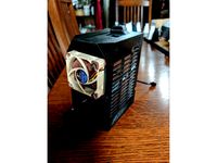
Prusa mk3 Einsy case with fan by darthmuffin
...tor if you're not using that. option b is to source a 24v 40mm fan (noctua doesn't make one, but they're out there).
Tiki
turbosquid
$15

tiki
... available on turbo squid, the world's leading provider of digital 3d models for visualization, films, television, and games.
design_connected
$18

Tiki Armchair
...tiki armchair
designconnected
fogia tiki armchair computer generated 3d model. designed by engesvik, andreas.
turbosquid
$5

Tiki Statue
...royalty free 3d model tiki statue for download as png and obj on turbosquid: 3d models for games, architecture, videos. (1424506)
turbosquid
$5

Tiki Torch
... available on turbo squid, the world's leading provider of digital 3d models for visualization, films, television, and games.
turbosquid
$3
TIKI Coffee Table
... 3d model coffee table tiki for download as 3ds, max, and obj on turbosquid: 3d models for games, architecture, videos. (1475529)
turbosquid
free

Totem Tiki Mask
...3d model totem tiki mask for download as ma, ma, fbx, and obj on turbosquid: 3d models for games, architecture, videos. (1630557)
design_connected
$29
Tiki 3-Seater Sofa
...tiki 3-seater sofa
designconnected
fogia tiki 3-seater sofa computer generated 3d model. designed by engesvik, andreas.
design_connected
$29
Tiki 2-Seater Sofa
...tiki 2-seater sofa
designconnected
fogia tiki 2-seater sofa computer generated 3d model. designed by engesvik, andreas.
3d_export
$29

USA Hawaii Tiki Totem 3D Model
...usa hawaii tiki totem 3d model
3dexport
usa hawaii tiki totem
usa hawaii tiki totem 3d model sophia 53075 3dexport
3d_export
$13

Tiki mask for wall decoration 3D Model
...all decoration 3d model
3dexport
tiki mask decoration wall interior
tiki mask for wall decoration 3d model zale85 101458 3dexport
Torch
3d_ocean
$16
Torch
...flashlight high poly model. day high poly torch light mag lite night lamp rays shine new torch torch
high detailed 3d torch model
design_connected
$13

Torch
...torch
designconnected
established & sons torch computer generated 3d model. designed by willenz, sylvain .
3ddd
$1
Baccarat - Torch
...- torch
3ddd
baccarat , torch
торшер фирмы baccarat, модель torch, текстуры прилагаются.
turbosquid
$10

Torch
...h
turbosquid
royalty free 3d model torch for download as max on turbosquid: 3d models for games, architecture, videos. (1364794)
turbosquid
$4

Torch
...h
turbosquid
royalty free 3d model torch for download as c4d on turbosquid: 3d models for games, architecture, videos. (1264168)
turbosquid
free

Torch
...urbosquid
free 3d model torch for download as , fbx, and obj on turbosquid: 3d models for games, architecture, videos. (1598202)
turbosquid
$5

torch
...quid
royalty free 3d model torch for download as max and stl on turbosquid: 3d models for games, architecture, videos. (1531004)
turbosquid
$1

Torch
...d
royalty free 3d model torch for download as , fbx, and obj on turbosquid: 3d models for games, architecture, videos. (1622961)
3d_export
free

torch
...torch
3dexport
turbosquid
$10
Torch
...
royalty free 3d model torch for download as ma, obj, and fbx on turbosquid: 3d models for games, architecture, videos. (1194449)
Led
3d_export
$5
led
...led
3dexport
the led is cut with all the parts.
3ddd
$1
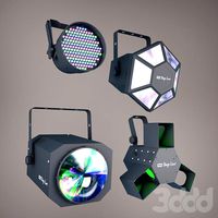
Monacor / PARL56DMX / LED-320RGBW / LED-345RGBW / LED-300RGB
... прожектор
http://www.monacor.dk/
parl56dmx
led-320rgbw
led-345rgbw
led-300rgb
turbosquid
$10
LED
...led
turbosquid
free 3d model led for download as blend on turbosquid: 3d models for games, architecture, videos. (1691856)
3d_export
$5

led lamp
...led lamp
3dexport
led lamp, brightness animation
3ddd
free
leds-c4
...leds-c4
3ddd
leds-c4
современный торшер
3ddd
free
leds-c4
...leds-c4
3ddd
leds-c4
настольный лампа
turbosquid
$19
LED
... available on turbo squid, the world's leading provider of digital 3d models for visualization, films, television, and games.
turbosquid
$12
Led
... available on turbo squid, the world's leading provider of digital 3d models for visualization, films, television, and games.
turbosquid
free
LED
... available on turbo squid, the world's leading provider of digital 3d models for visualization, films, television, and games.
turbosquid
free
LED
... available on turbo squid, the world's leading provider of digital 3d models for visualization, films, television, and games.