Thingiverse
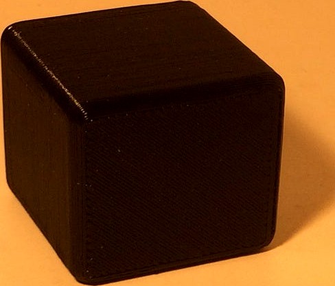
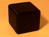
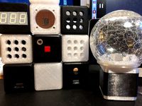
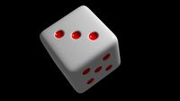
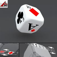
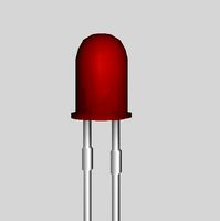
LED dice 29mm Harald edition
by Thingiverse
Last crawled date: 4 years, 3 months ago
This thing is a small dice derived from my universal cube system.https://www.thingiverse.com/thing:3926580
I have it designed on request by Harald Sattler.
Here you are.
Update:
Harald complained about messsing with his website.
Not true!
He wants you to visite his website.
Please bare with him, bring up his hit counters.
Anyway have removed a link to the depicted pcb.
Point at something, lead the reader directly to the target.
This is how the Internet works.
Give the poeples work respect.
Give them credit, some times pledge them some money.
Buy them a coffee.
But ignore stupid hard way IP protection efforts.
No offense intended.
.
If you are trying to enforce something I will simply remove your stuff from my thing.
PERIOD!
RELAX man!
.
With no doubt there are exist a few (or many?) solutions using multilexed or charlieplexed LED's.
Henrik Haftman made some hard and software designshttps://www-user.tu-chemnitz.de/~heha/
Example: turnaround LED light PCB file (Eagle format)https://www-user.tu-chemnitz.de/~heha/Mikrocontroller/LEDs/Eagle.zip
Schematics:https://www-user.tu-chemnitz.de/~heha/Mikrocontroller/LEDs/Rundum.pnghttps://www-user.tu-chemnitz.de/~heha/Mikrocontroller/LEDs/Rundum2.pnghttps://www-user.tu-chemnitz.de/~heha/Mikrocontroller/LEDs/Eagle.zip/rundum4.wmf?bin=SVG
He declares all his stuff comes (when available) with Open Source software.
So i assume nobody can start stupid DMCA requests.
.
Many readers are capable enough to make their own electronics.
Dear readers!
Please make a local copy of the projects files. No matter where they came from.
When you make something it would be a good idea to save tome files before they get lost anytime soon.
The cube size is 29mm.
Please take a simple CR1616 or CR2032 coin cell with lead wires or DIY made with heatshrink tube.
If you are going to make a pcb, DO NOT round the corners!
A square makes it much easier to place the pcb safely.
It allows for cutting off some plastic if soldered on parts occupy more space.
If you do not agree with Harald claims , make your own design.
The required pcb sice is a square of no more than 25.6.mm x 25.6mm
-NO cell coin holder please, the spacing inside the cube is tight
-Please use transparent or translucent filament here.
The light from the tiny LED's will not pass the black filament.
.
I DO NOT own a pcb according to the files provided by Harald Sattler on his website.
Please read:http://www.harald-sattler.de/html/attiny-wurfel.htmhttp://www.harald-sattler.de/html/attiny-wurfel_reloaded.htm
Safety requirements
Unfortunaly some glue might be requiered.
Be it hotglue, silicon, double sided duct tap, foam or whats not.
Please take care on insulating conductive parts of the pcb, cell coin, tactile switch.
This time I could not design as usual fastening the parts using screws.
The build hight of the stacked parts inside the cube may vary.
Pls, fill up the gap.
Otherwise the tactile switch could fall inside the cube when pushing it hard.
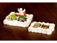
The files:
-electronics schematics file
-PCB design files provided by Harald Sattler (Eagle format)
-content of the website page as a pdf-file translated trough Google.
-assembly instruction (pictures only), needs to be modified still.
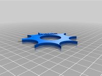
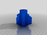
-the printable parts
the top (cover) with tactile switch
the base with electronics, cell coin battery
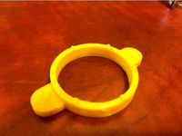
Distanzring / Shim( have no clue how you call it) it can be used as a retainer or to bridge a gap. Scale it to the thickness you want.
The Code:
No code provided by me.
See Haralds website.
He goes over some details on the code.
He describes how he transformed the PIC controller based electronics to ATTiny hardware.
His code is using routines what puts the MC to sleep when not active.
Printing the parts requires some attention.
By chance the printer setup requires printing support or skirt alongside the rounded edges.
If you dislike printing spupport or skirt; the stupid Up! software insists of printing it with support ( leaving no other choice) cut off a small portion from the top face of the parts (stl-file).
The LED face front section has a thicknes of 0,6mm.
It can be tricky to find the right spot.
Recommended printing with NO raft.
From my experience:
I made a print using raft it ripped the filament out of the small holes when separating the raft from the part.
I have it designed on request by Harald Sattler.
Here you are.
Update:
Harald complained about messsing with his website.
Not true!
He wants you to visite his website.
Please bare with him, bring up his hit counters.
Anyway have removed a link to the depicted pcb.
Point at something, lead the reader directly to the target.
This is how the Internet works.
Give the poeples work respect.
Give them credit, some times pledge them some money.
Buy them a coffee.
But ignore stupid hard way IP protection efforts.
No offense intended.
.
If you are trying to enforce something I will simply remove your stuff from my thing.
PERIOD!
RELAX man!
.
With no doubt there are exist a few (or many?) solutions using multilexed or charlieplexed LED's.
Henrik Haftman made some hard and software designshttps://www-user.tu-chemnitz.de/~heha/
Example: turnaround LED light PCB file (Eagle format)https://www-user.tu-chemnitz.de/~heha/Mikrocontroller/LEDs/Eagle.zip
Schematics:https://www-user.tu-chemnitz.de/~heha/Mikrocontroller/LEDs/Rundum.pnghttps://www-user.tu-chemnitz.de/~heha/Mikrocontroller/LEDs/Rundum2.pnghttps://www-user.tu-chemnitz.de/~heha/Mikrocontroller/LEDs/Eagle.zip/rundum4.wmf?bin=SVG
He declares all his stuff comes (when available) with Open Source software.
So i assume nobody can start stupid DMCA requests.
.
Many readers are capable enough to make their own electronics.
Dear readers!
Please make a local copy of the projects files. No matter where they came from.
When you make something it would be a good idea to save tome files before they get lost anytime soon.
The cube size is 29mm.
Please take a simple CR1616 or CR2032 coin cell with lead wires or DIY made with heatshrink tube.
If you are going to make a pcb, DO NOT round the corners!
A square makes it much easier to place the pcb safely.
It allows for cutting off some plastic if soldered on parts occupy more space.
If you do not agree with Harald claims , make your own design.
The required pcb sice is a square of no more than 25.6.mm x 25.6mm
-NO cell coin holder please, the spacing inside the cube is tight
-Please use transparent or translucent filament here.
The light from the tiny LED's will not pass the black filament.
.
I DO NOT own a pcb according to the files provided by Harald Sattler on his website.
Please read:http://www.harald-sattler.de/html/attiny-wurfel.htmhttp://www.harald-sattler.de/html/attiny-wurfel_reloaded.htm
Safety requirements
Unfortunaly some glue might be requiered.
Be it hotglue, silicon, double sided duct tap, foam or whats not.
Please take care on insulating conductive parts of the pcb, cell coin, tactile switch.
This time I could not design as usual fastening the parts using screws.
The build hight of the stacked parts inside the cube may vary.
Pls, fill up the gap.
Otherwise the tactile switch could fall inside the cube when pushing it hard.
The files:
-electronics schematics file
-PCB design files provided by Harald Sattler (Eagle format)
-content of the website page as a pdf-file translated trough Google.
-assembly instruction (pictures only), needs to be modified still.
-the printable parts
the top (cover) with tactile switch
the base with electronics, cell coin battery
Distanzring / Shim( have no clue how you call it) it can be used as a retainer or to bridge a gap. Scale it to the thickness you want.
The Code:
No code provided by me.
See Haralds website.
He goes over some details on the code.
He describes how he transformed the PIC controller based electronics to ATTiny hardware.
His code is using routines what puts the MC to sleep when not active.
Printing the parts requires some attention.
By chance the printer setup requires printing support or skirt alongside the rounded edges.
If you dislike printing spupport or skirt; the stupid Up! software insists of printing it with support ( leaving no other choice) cut off a small portion from the top face of the parts (stl-file).
The LED face front section has a thicknes of 0,6mm.
It can be tricky to find the right spot.
Recommended printing with NO raft.
From my experience:
I made a print using raft it ripped the filament out of the small holes when separating the raft from the part.
Similar models
thingiverse
free
LED cube 29mm standard dice edition
...system.https://www.thingiverse.com/thing:3926580 the cube size is 29mm. there is a similar cube thing i have designed and adopted to fit...
thingiverse
free
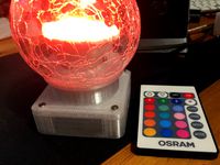
LED glas ball lamp with remote
...arding the light diffusion hackaday has an article.https://hackaday.com/2017/04/25/ask-hackaday-what-about-the-diffusers/
the end
3dwarehouse
free

Converter From USB To Parallel (full LPT, but at usb LowSpeed)
...b lowspeed)
3dwarehouse
design based on: http://www-user.tu-chemnitz.de/~heha/bastelecke/rund%20um%20den%20pc/usb2lpt/ul-khs.htm
thingiverse
free

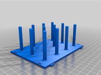
Scrying Pool with room for LEDs and Coin Cell Battery by industriald
... industriald
thingiverse
i made some holes for 3mm leds and hollowed out underneath to make room for a coin cell battery holder.
grabcad
free

Prototyping PCB LEDs
...yping pcbs ... also ... leds, tactile buttons, breadboard, jumper wires, capacitors, variable resistor trimming potentiometer ...
thingiverse
free
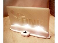
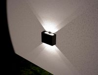
Logo LED Lamp by 3Dsection
...d´s.
if you like it and like to show some love, than please share it or add it to your list.
enjoy ! :)
joeyhills.de
3dsection.de
thingiverse
free
cube based system for decoration and technical applications
...not much travel! but it is doable. .https://components.rafi.de/de/de/media/fot_pv_racon8-tht-os_ing.jpg very similar the racon12 series, little bigger sized taster s76m (mechanical...
thingiverse
free

4x4x4 Led Cube Bottom PCB Cover by NotEnoughCheese
...uses 4 m3 screws.
it provides some basic protection against fingers and conductive surfaces, also makes the cube easier to carry.
thingiverse
free
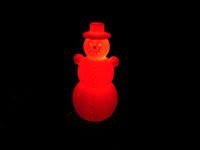
Snowman, Schneemann, 120MM, RGB LED slow-flashing cr2032 coin cell christmas by 3D_Print_Karlsruhe
.../prusa-i3-200x200x200
myminifactoryhttps://www.myminifactory.com/de/users/3d-print-ka
i'm from stutensee (karlsruhe, germany)
thingiverse
free

Diwali LED lamp by beamakerclub
...amp decoration. you'll need an led and coin cell battery to light it up or replace part 3 with another led light of your own.
Harald
turbosquid
$4
SpineMetalbase black harald
...ad as blend, 3ds, dae, dxf, fbx, obj, stl, usd, wrl, and gltf on turbosquid: 3d models for games, architecture, videos. (1612426)
thingiverse
free
Harald Bachmann by h-bachmann
...harald bachmann by h-bachmann
thingiverse
nähspulenhalterung 128mm 96mm, system für schubladenbreite 290mm 520mm
thingiverse
free

Christmas tree branch holder by HaraldS
...anch keeper.
inner diameter is about 33.5 mm, but you could probably scale it a little to fit your needs.
branch diameter 4.8 mm.
thingiverse
free
Catan Junior resource storage bin by HaraldS
...n for the resource cards from catan junior. both parts together fit nicely in the original catan junior box.
hope you like it. :)
thingiverse
free
Corner Hook for steel storage shelf (stålreol fra Harald Nyborg (varenr. 1004)) by BloodShed4REAL
...versions, a normal one with narrow hooks and a "large" one with larger hooks and a thicker body to support more weight.
3d_sky
free
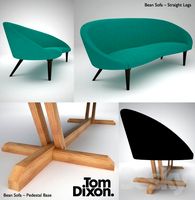
Tom Dixon / Bean Sofa
...bean sofa 3dsky aronsen base bean dixon fanny furniture harald kvadrat legs natural pedestal sofa straight tom wood sofa...
3d_sky
free
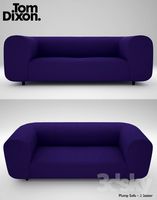
Tom Dixon / Plump Sofa 3Seater
...plump sofa 3seater 3dsky aronsen color dixon fanny furniture harald kvadrat seater sofa tom seats soft seat plump sofa-3...
thingiverse
free
cube based system for decoration and technical applications
...of a cr2032 driven ds3231rtc module with super condensator (german:doppelschicht-kondensator)http://www.haraldsattler.de/html/wordclock.htm#umbauminimodulhttp://www.harald-sattler.de/assets/images/autogen/2018-09-20_img_4884_resize.jpg . replace the mechanical switch by a capacitive approximation...
cg_trader
$20

Harald - Viking - Lowpoly Stylized
...lized
cg trader
3d model game-ready harald - viking - lowpoly stylized , formats include fbx, spp, ready for 3d animation and ot
29Mm
3d_export
free
Pin Metal
...more than 5 edges: 0<br>object:<br>- dimension mm: 14mm x 29mm x 3mm<br>- dimension cm: 1.4cm x 2.9cm x 0.3cm<br>-...
3d_export
$19
Guerlain Kisskiss Matte Lipstick
...more than 5 edges: 0<br>object:<br>- dimension mm: 139mm x 29mm x 110mm<br>- dimension cm: 13.9cm x 2.9cm x 11cm<br>-...
3d_export
$8
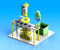
lifting transfer mechanism solidworks2016
...by image recognition.<br>object artifact<br>resin gear<br>workpiece specification: φ 34, height 29mmlt;br>characteristic<br>specification and size<br>overall dimension: 320 × 320 × 341mm<br>total height:...
thingiverse
free
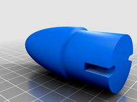
Stubby 29mm nosecone by etoyoc
...by 29mm nosecone by etoyoc
thingiverse
50mm long (not including coupler) nose cone for 29mm, this is less than a 2:1 elliptical.
thingiverse
free
Measure Corners 21mm to 29mm by KozzenLee
...measure corners 21mm to 29mm by kozzenlee
thingiverse
measure corners 21mm to 29mm. including cad files.
thingiverse
free
29mm rocket fin can by etoyoc
...29mm rocket fin can by etoyoc
thingiverse
29mm 4 fin can for phenolic body tube with screw on retainer
thingiverse
free
Wrench for Seiko Watch - 29mm by JumpyWizard
...9mm by jumpywizard
thingiverse
this is a wrench for the back panel of my seiko watch. the diameter from notch to notch is 29mm.
thingiverse
free

Solar light spike (D=29mm) by zellkoss
...spike (d=29mm)
feel free to take the .ipt file (inventor) and modify the part.
pique pour lampe solaire jumbo, diamètre 29mm.
thingiverse
free

Clothes rail hanger for 29mm poles by daveb500
...clothes rail hanger for 29mm poles by daveb500
thingiverse
wall bracket for hanging a clothes rail. rail diameter 29mm.
thingiverse
free

29mm 1/2inch Drive Socket by devonfurnell
...29mm 1/2inch drive socket by devonfurnell
thingiverse
29mm, 1/2inch drive socket i modeled for light duty use.
Dice
3d_export
$5

dice
...dice
3dexport
dice geometry
3d_export
$5
Dice
...dice
3dexport
a dice for poker
3d_ocean
$4
Dices
...dices
3docean
dice dices
this was created 3ds max 2014. file contains obj, 3ds, max, fbs file types.
3ddd
$1
dice+
...tic dice on electronic devices, in addition to technology.
everything made in 3ds max + vray blend material with light number.
3d_ocean
$2
dice
...dice
3docean
3ds arman3dg dice games low max poly
dice [2 texture color 512-128, 1024-256] (3ds max file- 2010, 2011, 2012)
turbosquid
free

Dice
...dice
turbosquid
free 3d model dice for download as blend on turbosquid: 3d models for games, architecture, videos. (1393051)
turbosquid
free
Dice
...dice
turbosquid
free 3d model dice for download as obj on turbosquid: 3d models for games, architecture, videos. (1310801)
turbosquid
free

Dice
...dice
turbosquid
free 3d model dice for download as blend on turbosquid: 3d models for games, architecture, videos. (1250342)
3d_export
$5

rol dice
...rol dice
3dexport
rol dices
3d_ocean
$3
Dice+Cards
...dice+cards
3docean
dice+cards
Led
3d_export
$5
led
...led
3dexport
the led is cut with all the parts.
3ddd
$1
Monacor / PARL56DMX / LED-320RGBW / LED-345RGBW / LED-300RGB
... прожектор
http://www.monacor.dk/
parl56dmx
led-320rgbw
led-345rgbw
led-300rgb
turbosquid
$10
LED
...led
turbosquid
free 3d model led for download as blend on turbosquid: 3d models for games, architecture, videos. (1691856)
3d_export
$5

led lamp
...led lamp
3dexport
led lamp, brightness animation
3ddd
free
leds-c4
...leds-c4
3ddd
leds-c4
современный торшер
3ddd
free
leds-c4
...leds-c4
3ddd
leds-c4
настольный лампа
turbosquid
$19
LED
... available on turbo squid, the world's leading provider of digital 3d models for visualization, films, television, and games.
turbosquid
$12
Led
... available on turbo squid, the world's leading provider of digital 3d models for visualization, films, television, and games.
turbosquid
free

LED
... available on turbo squid, the world's leading provider of digital 3d models for visualization, films, television, and games.
turbosquid
free
LED
... available on turbo squid, the world's leading provider of digital 3d models for visualization, films, television, and games.
Edition
turbosquid
$33
Natuzzi Editions
... available on turbo squid, the world's leading provider of digital 3d models for visualization, films, television, and games.
turbosquid
$29
Guitar_MJ-Edition
... available on turbo squid, the world's leading provider of digital 3d models for visualization, films, television, and games.
turbosquid
$20
Editable Fountain
... available on turbo squid, the world's leading provider of digital 3d models for visualization, films, television, and games.
3ddd
$1
Kueco Edition Palais
...kueco edition palais
3ddd
keuco
зеркальный шкаф kueco edition palais
design_connected
$16
369 Classic Edition
...369 classic edition
designconnected
walter knoll 369 classic edition computer generated 3d model.
3ddd
$1
Martz Edition
...martz edition
3ddd
martzedition
http://www.martzedition.com/a-500-3
3ddd
$1
Martz Edition
...martz edition
3ddd
martzedition
http://www.martzedition.com/b-400-3
design_connected
$25
Chester - Limited Edition
...nnected
established & sons chester - limited edition computer generated 3d model. designed by future systems, amanda levete.
3ddd
$1
KROKEN LIMITED EDITION
...d
rochebobois
autumn/winter collections 2012 rochebobois paris
kroken limited edition armchairhttp://m.roche-bobois.com
3ddd
$1
stilwerk limited edition
...stilwerk limited edition
3ddd
3000х1200х750