Thingiverse
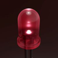
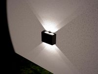
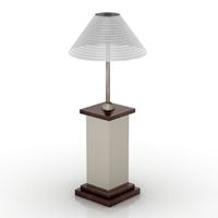
Led Bridge Lamp - bolted version by flash24
by Thingiverse
Last crawled date: 3 years ago
A remix of the Led Bridge Lamp by Opossums :
bolted version
foot parts printable on Flashforge Dreamer
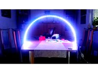
The wonderfull Led Bridge Lamp made by designer Opossums
(see https://www.thingiverse.com/thing:1639224) makes me think of
the Eiffel Tower.
The original design features relatively large 'tabs', marked 'Left'
and 'Right' on the segment sides.
These tabs are the reason the side- and top-parts of the segment need
to be printed with supports.
I was looking for a design that could be printed without supports
and came up with this alternative version :
CURVED and STRAIGHT SEGMENTS :
No more supports needed, no post-printing cleanup work, less
material wasted.
Segment sides Left and Right are now identical, and so are top
panels A and B - resulting in a more simple design.
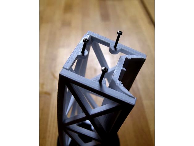
You WILL need a handfull of M2 bolts and (nylon lock) nuts to
inter-assemble the segments :
M2x10mm : 3 per segment
M2x6mm : 1 per curved segment
M2x20mm : 4 per foot
You will need a long, thin screwdriver to assemble the segments.
Segments can be assembled without glue (except for the LED
channels and top-to-side of course). If you use glue, the bolts
will keep the parts in place while the glue dries.
Base-plates 'mama' and 'papa' were redesigned to fit the M2 bolts
Straight segments were modified as well to match the bolted
assembly method.
The LED channel sides have been rounded - somehow this prints
cleaner on a Flashforge Dreamer at a cost of a little more PLA.
Try it out or use the original flat sided LED channels.
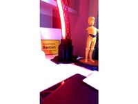
BRIDGE FOOT :
The Foot parts are too large for a Flashforge Dreamer printer-
platform so I resized the Foot Base, Center and Side parts.
The Foot Base now fits inside the Foot Center part
Foot parts Center, Cap and Height Extension can also be bolted
together using M2 bolts
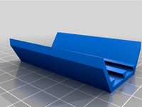
New design of the Foot Side part to use less filament.
Added small tabs to the top of the Foot Side-panels.
These tabs fit in the bottom of the Foot Cap, so you don't
have to glue the Foot Sides to the Foot Center part.
As I did not need electronics in the Foot Base, I added a
ballast-tray and glued 2 layers of M8 nuts and some lead
airgun pellets in between those and so added some 500gr of weight
per foot.
Sketchup files are included so you can modify parts if you need
some sort of PCB-board on top of the Foot Base ballast tray,
or if you use a different size/type of power inlet or switch.
Enjoy!
Printed on Flashforge Dreamer in PLA, no supports, no raft.
First layer max. speed 10mm/s, 30% infill - standard print resolution.
bolted version
foot parts printable on Flashforge Dreamer
The wonderfull Led Bridge Lamp made by designer Opossums
(see https://www.thingiverse.com/thing:1639224) makes me think of
the Eiffel Tower.
The original design features relatively large 'tabs', marked 'Left'
and 'Right' on the segment sides.
These tabs are the reason the side- and top-parts of the segment need
to be printed with supports.
I was looking for a design that could be printed without supports
and came up with this alternative version :
CURVED and STRAIGHT SEGMENTS :
No more supports needed, no post-printing cleanup work, less
material wasted.
Segment sides Left and Right are now identical, and so are top
panels A and B - resulting in a more simple design.
You WILL need a handfull of M2 bolts and (nylon lock) nuts to
inter-assemble the segments :
M2x10mm : 3 per segment
M2x6mm : 1 per curved segment
M2x20mm : 4 per foot
You will need a long, thin screwdriver to assemble the segments.
Segments can be assembled without glue (except for the LED
channels and top-to-side of course). If you use glue, the bolts
will keep the parts in place while the glue dries.
Base-plates 'mama' and 'papa' were redesigned to fit the M2 bolts
Straight segments were modified as well to match the bolted
assembly method.
The LED channel sides have been rounded - somehow this prints
cleaner on a Flashforge Dreamer at a cost of a little more PLA.
Try it out or use the original flat sided LED channels.
BRIDGE FOOT :
The Foot parts are too large for a Flashforge Dreamer printer-
platform so I resized the Foot Base, Center and Side parts.
The Foot Base now fits inside the Foot Center part
Foot parts Center, Cap and Height Extension can also be bolted
together using M2 bolts
New design of the Foot Side part to use less filament.
Added small tabs to the top of the Foot Side-panels.
These tabs fit in the bottom of the Foot Cap, so you don't
have to glue the Foot Sides to the Foot Center part.
As I did not need electronics in the Foot Base, I added a
ballast-tray and glued 2 layers of M8 nuts and some lead
airgun pellets in between those and so added some 500gr of weight
per foot.
Sketchup files are included so you can modify parts if you need
some sort of PCB-board on top of the Foot Base ballast tray,
or if you use a different size/type of power inlet or switch.
Enjoy!
Printed on Flashforge Dreamer in PLA, no supports, no raft.
First layer max. speed 10mm/s, 30% infill - standard print resolution.
Similar models
thingiverse
free

Flashforge Dreamer printer foot by jamesarm97
...7
thingiverse
needed some rubber feet for the flashforge dreamer printer. print this (x4) in semiflex (preferred) or ninjaflex.
thingiverse
free
Led Arc Lamp by Niyada
...and
the surrounding area)
in one of the feet is a hole for a potentiometer, one for a power source and one for the led connectors
thingiverse
free

Led bridge lamp Universal Segment by Opossums
...ller? scale middle piece of the foot.
now includes straight segment.
thank you, 50 000 + viewers of the original led bridge lamp!
thingiverse
free
New Foot / Base for the great Led Bridge Lamp by Opossums by BplusO
...ed into the led light guides (instead of the led channels that create shafts that are too small when scaling) - here in 1:1 scale
thingiverse
free

LED Bridge Lamp Remix by Protopix
...he led guides and channels have been replaced with custom versions.
many thanks to opossums for his original bridge lamp designs!
thingiverse
free

LED Bridge Alternative Foot and Channels by BFerreira
...of two cabinets. the foots is designed to be similar to the bridge structure. i've also changed the channels...
thingiverse
free

FlashForge Dreamer spool holders by DaveMoi
...will need to print both the base and the screw-on spool holder bar. the center bar that interconnect the two holders is optional.
thingiverse
free
Remixed Channel parts for Opossum's Led bridge lamp by Tirpitz93
...t replace the light guides with the provided components.
i am printing mine in petg and assembling using dcm for a chemical weld.
thingiverse
free

Flashforge Door Lock Dreamer/Inventor by C_Birch81
... by it's self so this just pushes into place to lock the door open and as a tab to remove it when you need to close the door.
thingiverse
free

FlashForge Dreamer Side Vent cover by Willg77
...flashforge dreamer side vent cover by willg77
thingiverse
just in case, you have lost your side cover.
support need for print.
Flash24
thingiverse
free

Another Solder Holder by flash24
...another solder holder by flash24
thingiverse
simple solder holder
thingiverse
free

OTTO DIY - Foot Remix by flash24
...otto diy - foot remix by flash24
thingiverse
remix of the otto diy robot foot with toes.
thingiverse
free
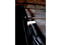
IBC Clip by flash24
...elf (or other) to the metal top frame of an ibc container.
no supports, no raft, infill depending on weight of shelf : 30% or up.
thingiverse
free

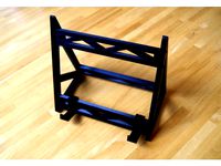
Modular Plier Stand by flash24
... as you need and glue them together.
update oct. 29 2018
added 2 extra elements for those that want to fix the rack to a wall.
thingiverse
free
Simple Strong Book Stand by flash24
...able
book almost flat - in case you're standing (e.g. kitchen situation)
use m2x15 or m2x20 bolts and super glue to assemble.
thingiverse
free

Simple H0-scale Bridge Pillar - adjustable by flash24
... part, you may need to
minimize the depth of the m2 holes (10 mm. is probably deep enough) in
sketchup to print this part faster.
thingiverse
free

Funnel with OPEN-CLOSE Mechanism by flash24
... % infill.
update : made version 2 of part 2 : the thumb-end is now thinner, resulting in more 'reach' at the pencil-end.
thingiverse
free
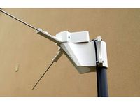
V-dipole antenna construction set by flash24
..., they go straight into the choc blocks
you only need to solder 2 short wires between the so239 and the 2 choc blocks
enjoy !
thingiverse
free

Solenoid Valve Cover + LED slot by flash24
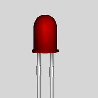
...is a new cover-version for a simple round 5mm. led.
pack of 20 pcs. 5mm. 12v led's here
pack of 50 black 5mm. led holder here
thingiverse
free

Another 18650 Charger Station by flash24
...
solder everything and test
evt. glue wires in place on the underside of the inner frame
glue exterior shell over the inner frame
Bridge
3d_export
free
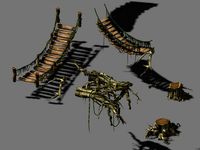
bridge and destroyed bridge
...bridge and destroyed bridge
3dexport
bridge and destroyed bridge
3d_ocean
$19
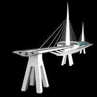
Bridge
...bridge
3docean
3d bridge building
3d bridge
archibase_planet
free

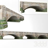
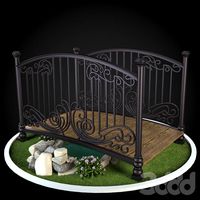
Bridge
...bridge
archibase planet
bridge foot-bridge construction
bridge n130715 - 3d model (*.gsm+*.3ds) for exterior 3d visualization.
3ddd
free
The Bridge
...the bridge
3ddd
мост
the bridge
3d_ocean
$7
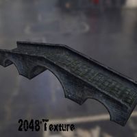
Bridge
...bridge
3docean
bridge low polygon medi evil bridge old bridge
2048 * texture obj, fbx and blend format. game ready model.
archibase_planet
free
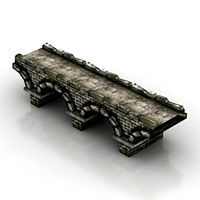
Bridge
...net
bridge foot-bridge construction
bridge ponte de tijolos n250515 - 3d model (*.gsm+*.3ds+*.max) for exterior 3d visualization.
3d_export
$18
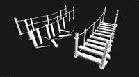
arch bridge-bridge-stairs
...arch bridge-bridge-stairs
3dexport
arch bridge-bridge-stairs<br>3ds max 2015
3d_export
$5

bridge
...bridge
3dexport
bridge - 3d model ( gsm : 3ds )
3d_export
$5

bridge
...bridge
3dexport
wood bridge all textures in 4k
3ddd
$1
Bridge
...bridge
3ddd
bridge , мост
мост для экстерьера
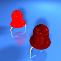
Led
3d_export
$5
led
...led
3dexport
the led is cut with all the parts.
3ddd
$1
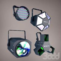
Monacor / PARL56DMX / LED-320RGBW / LED-345RGBW / LED-300RGB
... прожектор
http://www.monacor.dk/
parl56dmx
led-320rgbw
led-345rgbw
led-300rgb
turbosquid
$10
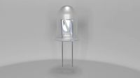
LED
...led
turbosquid
free 3d model led for download as blend on turbosquid: 3d models for games, architecture, videos. (1691856)
3d_export
$5

led lamp
...led lamp
3dexport
led lamp, brightness animation
3ddd
free
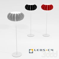
leds-c4
...leds-c4
3ddd
leds-c4
современный торшер
3ddd
free
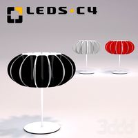
leds-c4
...leds-c4
3ddd
leds-c4
настольный лампа
turbosquid
$19
LED
... available on turbo squid, the world's leading provider of digital 3d models for visualization, films, television, and games.
turbosquid
$12
Led
... available on turbo squid, the world's leading provider of digital 3d models for visualization, films, television, and games.
turbosquid
free
LED
... available on turbo squid, the world's leading provider of digital 3d models for visualization, films, television, and games.
turbosquid
free

LED
... available on turbo squid, the world's leading provider of digital 3d models for visualization, films, television, and games.
Bolted
3d_export
$2
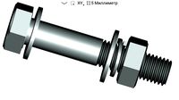
bolt
...
bolt - a fastener in the form of a rod with an external thread, usually with a hex head wrench, forming a connection with a nut.
3d_export
$5
bolted ring
...bolted ring
3dexport
bolted ring
3d_export
$5
royal bolt
...royal bolt
3dexport
royal bolt
turbosquid
$10
Bolt
...lty free 3d model bolt for download as max, c4d, obj, and fbx on turbosquid: 3d models for games, architecture, videos. (1681373)
turbosquid
$10
Bolt
...lty free 3d model bolt for download as max, c4d, obj, and fbx on turbosquid: 3d models for games, architecture, videos. (1680879)
turbosquid
$10

Bolt
...lty free 3d model bolt for download as max, c4d, obj, and fbx on turbosquid: 3d models for games, architecture, videos. (1680869)
turbosquid
$10

Bolt
...lty free 3d model bolt for download as max, c4d, obj, and fbx on turbosquid: 3d models for games, architecture, videos. (1680866)
turbosquid
$10
Bolt
...lty free 3d model bolt for download as max, c4d, obj, and fbx on turbosquid: 3d models for games, architecture, videos. (1680860)
turbosquid
$10

Bolt
...lty free 3d model bolt for download as max, c4d, fbx, and obj on turbosquid: 3d models for games, architecture, videos. (1680480)
turbosquid
$13
bolt
... available on turbo squid, the world's leading provider of digital 3d models for visualization, films, television, and games.
Lamp
archibase_planet
free
Lamp
...lamp
archibase planet
lamp reading lamp table lamp
lamp - 3d model (*.gsm+*.3ds) for interior 3d visualization.
archibase_planet
free
Lamp
...lamp
archibase planet
lamp reading lamp table lamp
lamp - 3d model (*.gsm+*.3ds) for interior 3d visualization.
archibase_planet
free

Lamp
...lamp
archibase planet
lamp table lamp reading lamp
lamp - 3d model (*.gsm+*.3ds) for interior 3d visualization.
archibase_planet
free

Lamp
...lamp
archibase planet
lamp table lamp reading lamp
lamp - 3d model (*.gsm+*.3ds) for interior 3d visualization.
archibase_planet
free
Lamp
...lamp
archibase planet
lamp reading lamp table lamp
lamp - 3d model (*.gsm+*.3ds) for interior 3d visualization.
archibase_planet
free
Lamp
...lamp
archibase planet
lamp reading lamp table lamp
lamp - 3d model (*.gsm+*.3ds) for interior 3d visualization.
archibase_planet
free
Lamp
...lamp
archibase planet
lamp table lamp reading lamp
lamp - 3d model (*.gsm+*.3ds) for interior 3d visualization.
archibase_planet
free

Lamp
...lamp
archibase planet
lamp table lamp reading lamp
lamp - 3d model (*.gsm+*.3ds) for interior 3d visualization.
archibase_planet
free
Lamp
...lamp
archibase planet
lamp reading lamp table lamp lantern
lamp - 3d model (*.3ds) for interior 3d visualization.
3d_ocean
$6
Lamp
...lamp
3docean
lamp
a high quality lamp.
Version
3ddd
$1
Diamond version
...nd , version , ванна
visionnaire - diamond bath
turbosquid
$50
LibraryMini Version
...free 3d model librarymini version for download as max and jpg on turbosquid: 3d models for games, architecture, videos. (1617724)
design_connected
$34
Barocco Version 01
...barocco version 01
designconnected
zanotta barocco version 01 computer generated 3d model. designed by progetti, emaf.
design_connected
$27

Barocco Version 02
...barocco version 02
designconnected
zanotta barocco version 02 computer generated 3d model. designed by progetti, emaf.
turbosquid
free
![Door [2 versions]](/t/13243146.jpg)
Door [2 versions]
...rbosquid
free 3d model door [2 versions] for download as fbx on turbosquid: 3d models for games, architecture, videos. (1223985)
turbosquid
$2
seat version 0.1
...
royalty free 3d model seat version 0.1 for download as blend on turbosquid: 3d models for games, architecture, videos. (1432653)
3d_export
$10

magnolia grandiflora mature version
...magnolia grandiflora mature version
3dexport
magnolia grandiflora mature version
3d_export
$8
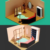
room assets and voxel version
...room assets and voxel version
3dexport
room assets and voxel version
turbosquid
$35

Zil Civilian version
... model zil civilian version for download as cgf, fbx, and obj on turbosquid: 3d models for games, architecture, videos. (1639420)
turbosquid
$3
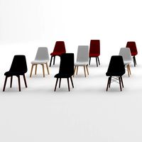
Chair 3 versions
...3d model chair 3 versions for download as blend, fbx, and obj on turbosquid: 3d models for games, architecture, videos. (1657530)