Thingiverse
KHAT - Kossel Hotend Attachment Tool
by Thingiverse
Last crawled date: 4 years, 3 months ago
KHAT
Kossel Hotend Attachment ToolAssembly Video - Youtube
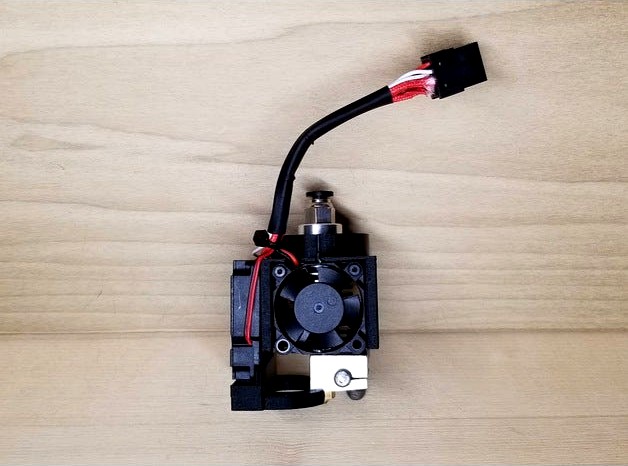
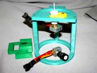
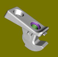
The 'Kossel Hotend Attachment Tool' is powerful interchangeable setup designed to make swapping hotends a quick task. This tools works with the Aluminum Fisheye Effector. With this setup, you can have multiple hotend assemblies ready to swap out with ease! No more changing nozzles all the time, when you can just have multiple assemblies to swap out!
Bill Of Materials
1x - M3 Single Print head aluminum fisheye effector (if not owned already)eBay
1x - Molex Micro-Fit 3.0 Dual Row (8 Circuits) Male & Female Receptacle PlugAmazon or eBay
2x - M3 x 6mm x 5mm Brass Knurled Nuts
4x - M2 x 4mm x 3.5mm Brass Knurled NutsAmazon Kit
2x - M3 x 10mm Hex Socket Head Screws
2x - M2 x 4mm Hex Socket Head Screws
2x - M2 x 12mm Hex Socket Head ScrewsAmazon Kit
1x - 4010 blower fan - 12vAmazon or eBay
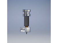
1x - E3D v6 Clone Kit (with 30mm fan, heatblock, heatsink, thermistor, heater)Amazon - Better kit or eBay - 2nd Amazon option
Optional stuff to make it pretty:
Shrink Tubing - Amazon
Zip Ties - Amazon
If you need parts individually for the connectors, the Molex numbers are:
Molex 43025-0800 Female connector
Molex 43020-0801 Male connector
Molex 43031-0001 Male Terminal Pin
Molex 43030-0001 Female Terminal Pin
Printing
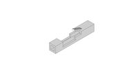
Print the khat_left.stl and khat_right.stl files together.
0.2mm layer height, 20% infill with supports.
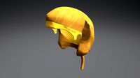
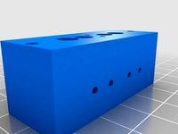
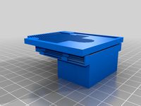
Print the khat_cooler.stl by itself.
0.2mm layer height, 20% infill without supports.
Assembly
Brass Knurl Nut Installation
Using any soldering iron, heat up and press in the brass knurl nuts into the printed parts. The smaller M2 brass knurl nuts will press into the fan holes, on the outside (standoff side), and the top internal holes. These will be used for the 40mm and 30mm fans.
The two larger M3 brass knurl nuts press into the top ring, to be used to attach to the aluminum effector.
Hotend Installation
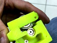
Put the assembled E3D v6 Hotend into the assembly.
You'll want to make double sure you've installed the nozzle into the heatblock correctly!! (Look up '3D printing guides - Assembling the E3D v6 hotend' by Thomas Sanladerer)
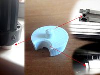
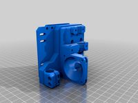
Once you've got the E3D v6 hotend installed, align it so the nozzle is closer to the side with the standoffs for the 40mm fan (see picture). Snap the two sides together and move on to the fan install.
Fan Installation
The larger fan (40mm) installs to the outside of the assembly with the blower opening facing downward. Use 2x M2 4mm to 6mm screws to attach to the face. The wiring should run along the side with the smaller fan.
Install the smaller fan (30mm) fan into the cove of the assembly. You'll want the wiring facing up, running out of the notch cut for it. Use 2x M2 12mm screws on the top to affix it to the assembly.
Wiring Warning
The wiring is probably the most time consuming and tedious part of this whole build. TAKE YOUR TIME AND DO IT RIGHT!!! I'm not even kidding. I messed this up a couple times and have never been more frustrated! If you don't get the crimps correct, your wires will pull out, come loose, or worse. I'm not even joking, unless you have a pin removal tool for these, a placed or botched pin will ruin the entire connector.
The official Molex crimp tool is stupid crazy expensive (like $300+). Not paying that. I was able to crimp the Molex Micro-fit 3.0 pins using a SN-28B Dupont Crimper, being very careful to not crimp past the wire folds. Cheaper, does about the same job.
You'll only need one female plug, which runs back into whatever mainboard you have. Though, it doesn't hurt to order the pack that comes with male and female, just to have some extras on hand.
Plan out how you'll have your wires, a pattern easy for you to remember and replicate.
You'll need to reuse the same formation when building more of these.
Wiring
Run all your wires together on the corner of the small and large fan.
Zip tie them together here, as a base point.
Leave about 80mm (3 inches) of wire from the top of the assembly. Cut the excess.
Strip back the wires the same length in preparation for crimping.
Using the SN-28B crimper, crimp just the two sets of flaps meant for the wire.
DO NOT CRIMP THE PIN LOCKING NOTCHES!
Verify all your crimps are good. For real, this is your last chance.
Insert pins into connector in whatever pattern you decided on.
To Do
Add bed leveling attachments.
Make a video detailing assembly (especially the pin crimps).
Change Log
Jan 12, 2020 - Added assembly video on Youtube
Jan 15, 2020 - Updated links, some sellers were sold out
Kossel Hotend Attachment ToolAssembly Video - Youtube
The 'Kossel Hotend Attachment Tool' is powerful interchangeable setup designed to make swapping hotends a quick task. This tools works with the Aluminum Fisheye Effector. With this setup, you can have multiple hotend assemblies ready to swap out with ease! No more changing nozzles all the time, when you can just have multiple assemblies to swap out!
Bill Of Materials
1x - M3 Single Print head aluminum fisheye effector (if not owned already)eBay
1x - Molex Micro-Fit 3.0 Dual Row (8 Circuits) Male & Female Receptacle PlugAmazon or eBay
2x - M3 x 6mm x 5mm Brass Knurled Nuts
4x - M2 x 4mm x 3.5mm Brass Knurled NutsAmazon Kit
2x - M3 x 10mm Hex Socket Head Screws
2x - M2 x 4mm Hex Socket Head Screws
2x - M2 x 12mm Hex Socket Head ScrewsAmazon Kit
1x - 4010 blower fan - 12vAmazon or eBay
1x - E3D v6 Clone Kit (with 30mm fan, heatblock, heatsink, thermistor, heater)Amazon - Better kit or eBay - 2nd Amazon option
Optional stuff to make it pretty:
Shrink Tubing - Amazon
Zip Ties - Amazon
If you need parts individually for the connectors, the Molex numbers are:
Molex 43025-0800 Female connector
Molex 43020-0801 Male connector
Molex 43031-0001 Male Terminal Pin
Molex 43030-0001 Female Terminal Pin
Printing
Print the khat_left.stl and khat_right.stl files together.
0.2mm layer height, 20% infill with supports.
Print the khat_cooler.stl by itself.
0.2mm layer height, 20% infill without supports.
Assembly
Brass Knurl Nut Installation
Using any soldering iron, heat up and press in the brass knurl nuts into the printed parts. The smaller M2 brass knurl nuts will press into the fan holes, on the outside (standoff side), and the top internal holes. These will be used for the 40mm and 30mm fans.
The two larger M3 brass knurl nuts press into the top ring, to be used to attach to the aluminum effector.
Hotend Installation
Put the assembled E3D v6 Hotend into the assembly.
You'll want to make double sure you've installed the nozzle into the heatblock correctly!! (Look up '3D printing guides - Assembling the E3D v6 hotend' by Thomas Sanladerer)
Once you've got the E3D v6 hotend installed, align it so the nozzle is closer to the side with the standoffs for the 40mm fan (see picture). Snap the two sides together and move on to the fan install.
Fan Installation
The larger fan (40mm) installs to the outside of the assembly with the blower opening facing downward. Use 2x M2 4mm to 6mm screws to attach to the face. The wiring should run along the side with the smaller fan.
Install the smaller fan (30mm) fan into the cove of the assembly. You'll want the wiring facing up, running out of the notch cut for it. Use 2x M2 12mm screws on the top to affix it to the assembly.
Wiring Warning
The wiring is probably the most time consuming and tedious part of this whole build. TAKE YOUR TIME AND DO IT RIGHT!!! I'm not even kidding. I messed this up a couple times and have never been more frustrated! If you don't get the crimps correct, your wires will pull out, come loose, or worse. I'm not even joking, unless you have a pin removal tool for these, a placed or botched pin will ruin the entire connector.
The official Molex crimp tool is stupid crazy expensive (like $300+). Not paying that. I was able to crimp the Molex Micro-fit 3.0 pins using a SN-28B Dupont Crimper, being very careful to not crimp past the wire folds. Cheaper, does about the same job.
You'll only need one female plug, which runs back into whatever mainboard you have. Though, it doesn't hurt to order the pack that comes with male and female, just to have some extras on hand.
Plan out how you'll have your wires, a pattern easy for you to remember and replicate.
You'll need to reuse the same formation when building more of these.
Wiring
Run all your wires together on the corner of the small and large fan.
Zip tie them together here, as a base point.
Leave about 80mm (3 inches) of wire from the top of the assembly. Cut the excess.
Strip back the wires the same length in preparation for crimping.
Using the SN-28B crimper, crimp just the two sets of flaps meant for the wire.
DO NOT CRIMP THE PIN LOCKING NOTCHES!
Verify all your crimps are good. For real, this is your last chance.
Insert pins into connector in whatever pattern you decided on.
To Do
Add bed leveling attachments.
Make a video detailing assembly (especially the pin crimps).
Change Log
Jan 12, 2020 - Added assembly video on Youtube
Jan 15, 2020 - Updated links, some sellers were sold out
Similar models
thingiverse
free

Titan Extruder mount for Lulzbot Taz 6 with E3D V6 Hotend by StephS
... housing (digikey pn: wm2525-nd)
20x male crimp connectors (digikey pn: wm2517-nd)
misc m3 screws for fan mounting.
printed parts
thingiverse
free

Tevo Tarantula stock carriage e3d V6 mount by martinussanders
...ge. requires 2x m2 bolts/nuts to attach to the stock carriage, also requires 2x m2 bolts/nuts to attach the pieces to each other.
thingiverse
free

Delta Effector for E3D V6 by Osechi
...effector offset : 25mm
i use the following parts,
・lj12a3-4-z-bx
・e3d v6 hotend
・3010 fans
・3010 blower fan
・m3 screws & nuts
thingiverse
free
![Prusa i3 Hephestos Bowden head V4 [E3D V6-BL TOUCH] by David_L_G](/t/8610440.jpg)
Prusa i3 Hephestos Bowden head V4 [E3D V6-BL TOUCH] by David_L_G
...usa, works pretty good.
bill of materials :
1x e3d v6 hotend kit
1x 40mm fan
1x m3x16 screw
1x m3 nuts
2x m4x20 screws
2x m4 nuts
thingiverse
free

Kossel Mini Delta Effector For E3D V6 With Dual Fan Mount by cristiprefac
...mount, so you can use auto bed leveling with it (see the pics).
you'll need a bunch of m3 screws and nuts to put it together.
thingiverse
free

DELTACOMB Simple Magnetic Effector for E3d V6 by kaleidoscopeit
...te : http://www.deltacomb.com/
reprap wiki : http://reprap.org/wiki/deltacomb
gthub : https://github.com/kaleidoscopeit/deltacomb
3dwarehouse
free
MOLEX Crimp Connector
...molex crimp connector
3dwarehouse
molex crimp connector. #electronics, #connector, #molex, #wiring
thingiverse
free

Ultimate Anycubic Predator Effector (V6 & 4010 fans) by Superbeasti
...6 iterations the design featured a similar enclosed hotend shroudsimilar to rosch8's great effector designs allowing the air to...
thingiverse
free

E3D V6 fan duct for bed and hotend by HgArgen
...3d v6 fan duct for bed and hotend.
it allows to install in all positions.
for 40 mm fan and m3 screws and nuts.
work in progress!
thingiverse
free

Trium3D E3D Effector Fan Duct by LeeIIIWill
...remixed from euphy's e3d v6 duct. uses 2x 40mm fans. may modify farther in the future for more direct air flow to the hotend.
Khat
sketchfab
$6
Afnet Crown B (khat)
...l ka.
*1 model (medium poly) with textures and materials. - afnet crown b (khat) - buy royalty free 3d model by shimtimultimedia
thingiverse
free

Khat kufi by Zarin
...r's work, nice design man
i just separate the calligraphy of allah and muhammad and scale them to have a 20cm*20cm dimension.
grabcad
free

khat khufi
...khat khufi
grabcad
caligrafi
cg_trader
$5

DECORATION KHAT
...oration khat
cg trader
3d decoration khat decoration furniture interior design decor, formats skp, ready for 3d animation and ot
grabcad
free

Khat Muhammad - Arabic Logos
...our car accessories, can be mounted on the back logos for toyota rush and daihatsu terios
-muhammad shallallahu alaihi wasallam-
grabcad
free

hat
...hat grabcad khat ...
cg_trader
$15

Cathinone molecule
...chemically similar to ephedrine, cathine, methcathinone and other amphetamines. khat has been cultivated in north africa and the arabian...
cg_trader
$20

Charpai 3d Model
...bedroom indian seating wooden charpa couch blankets pillows knitted khat manji charpaya charpoy bedroom furniture wooden...
3dwarehouse
free
Khat(4pai)
...khat(4pai)
3dwarehouse
village life khat(4pai) for the villages because thay are leave in village
Kossel
thingiverse
free

kossel bottom by keisukelin
...kossel bottom by keisukelin
thingiverse
kossel bottom
thingiverse
free
Leg for kossel by exelon
...leg for kossel by exelon
thingiverse
leg for kossel
thingiverse
free
Extruder for kossel by spencer_chen7
...extruder for kossel by spencer_chen7
thingiverse
extruder for kossel
thingiverse
free

Kossel parts by breezer83
...kossel parts by breezer83
thingiverse
kossel parts
thingiverse
free
Anycubic Kossel PID calibration
...ir mount:
kossel raspberry camera ir mount
extruder pid calibration.
simple extruder temperature calibration of your 3d printer.
thingiverse
free

Kossel Medium by flux83
...kossel medium by flux83
thingiverse
vertex for upgraded kossel mini
thingiverse
free

Kossel Mini by salesmendesandre
...kossel mini by salesmendesandre
thingiverse
custom kossel mini
frame 20x20
thingiverse
free

leg for kossel by ionulet
...leg for kossel by ionulet
thingiverse
leg for kossel with channel for end- stop cables
thingiverse
free

Optical Endstops Mounts for Kossel (with Better Kossel carriages) by dellfer
...stops on the anycubic kossel with better kossel carriages by codefreak https://www.thingiverse.com/thing:2501337
more precission
thingiverse
free

kossel??????? by wangrui19890704
...kossel??????? by wangrui19890704
thingiverse
??2020?2060???
Hotend
thingiverse
free
hotend by fablab_lueneburg
...hotend by fablab_lueneburg
thingiverse
hotend model
thingiverse
free
Hotend for Graber
...hotend for graber
thingiverse
hotend complement pastes for graber printerhttps://youtu.be/0koxhnsuhdy
thingiverse
free
Hotend adapter by antaviana
...hotend adapter by antaviana
thingiverse
hotend adapter
thingiverse
free
hotend fan by mming1106
...hotend fan by mming1106
thingiverse
hotend fan
thingiverse
free

Hotend schema by ione
...hotend schema by ione
thingiverse
hotend project schema
thingiverse
free
Fabtotum XY Hotend holder for E3D Hotend
...s with integrated supports.
more for the project you can see here: https://kf-designs.com/2019/09/07/fabtotum-printer-conversion/
thingiverse
free
HotEnd Stand by onepointdiy
...tend, when you make your new hotend or repair your j-head or mg-plus hotend.
the hole of 16mm, please adjust using a reamer, etc.
thingiverse
free

fast magnetic hotend changer for Chimera Hotend by Draman
...chimera hotend !
and new basis (the hole from original is to small)
it is a remix form skimmy's fast magnetic hotend changer
thingiverse
free

Hotend Fan Adapter for MicroSwiss All Metal Hotend by jo_schi_man
...
thingiverse
little change for the hotend fan adapter to hold the microswiss all metal hotend (slightly longer and sharp edges).
thingiverse
free
Merlin Hotend by Alejanson
...merlin hotend by alejanson
thingiverse
this is a 1:1 drawing of the classic merlin hotend.
Tool
turbosquid
$21
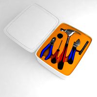
Tool box with tools
... available on turbo squid, the world's leading provider of digital 3d models for visualization, films, television, and games.
archibase_planet
free
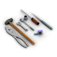
Tools
...tools
archibase planet
tools instruments implements
tools n070114 - 3d model (*.gsm+*.3ds+*.max) for interior 3d visualization.
3d_ocean
$12
Tools
...tools
3docean
hammer metal old screw tools wrench
maya
turbosquid
$6
Tool Cart / Tool Box
...
royalty free 3d model tool cart / tool box for download as on turbosquid: 3d models for games, architecture, videos. (1241859)
3d_ocean
$15

crimp tool
... tool copper cutter crimp crimp tool electrical electrical tools press tools pressing tool tools wire cutter
created in maya 2013
3d_ocean
$5

Tools
...tools
3docean
3d models paint tools work
3d,models,works,paint,art,create,working,
3d_export
free
tools
...tools
3dexport
coldsteel
turbosquid
$15
Tools
...turbosquid
royalty free 3d model tools for download as blend on turbosquid: 3d models for games, architecture, videos. (1331352)
3ddd
$1
bar tool
...bar tool
3ddd
барный
bar tool
turbosquid
$35

tools
... available on turbo squid, the world's leading provider of digital 3d models for visualization, films, television, and games.
Attachment
turbosquid
$20
M4A1 + Attachements
... available on turbo squid, the world's leading provider of digital 3d models for visualization, films, television, and games.
turbosquid
$19

Attached House
... available on turbo squid, the world's leading provider of digital 3d models for visualization, films, television, and games.
turbosquid
$15
Attache case
... available on turbo squid, the world's leading provider of digital 3d models for visualization, films, television, and games.
cg_studio
$75

Attached House3d model
...d model
cgstudio
.3ds .fbx .max .obj - attached house 3d model, royalty free license available, instant download after purchase.
turbosquid
$2
M416 AR with attachments
... model m416 ar with attachments for download as blend and fbx on turbosquid: 3d models for games, architecture, videos. (1614294)
turbosquid
$10

M16A2 with M203 Attachment
... available on turbo squid, the world's leading provider of digital 3d models for visualization, films, television, and games.
turbosquid
$3

bench attached to greenery
... available on turbo squid, the world's leading provider of digital 3d models for visualization, films, television, and games.
turbosquid
$3

Modern 1911 with Attachments
... available on turbo squid, the world's leading provider of digital 3d models for visualization, films, television, and games.
3d_export
$8
Mercedes Sprinter sun visor attachment
...mercedes sprinter sun visor attachment
3dexport
mercedes sprinter sun visor attachment
turbosquid
$14
Residential building with attached shop
...l residential building with attached shop for download as max on turbosquid: 3d models for games, architecture, videos. (1482935)