Thingiverse
Joint (double ball joint) and support system by simonwebnet
by Thingiverse
Last crawled date: 3 years, 1 month ago
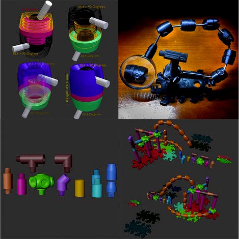
A version of the ball joint that allows you to manage large angles with continuous modulation of the clutch and that maintains reduced dimensions and strength, combined with a modular system that can be completely configured in any size and shape, to cover the different needs that may arise.
Starting from the joint, which is the most elaborate part of the system, you can see that there is an evolution in the model, but each version has some features that are worth considering to see which one suits the needs best.
In addition to the structural and performance differences, there are also differences in the work required for assembly.
Versions 1.0 and 1.5 are similar for the assembly procedure and differ in load capacities, which are obviously greater in version 1.5 which is slightly larger.
Version 2.0 is an evolution in which I tried to exploit the greater resistance of the printed material in the direction of the effort it has to support instead of with the perpendicular layers and thanks to this system I was able to make a joint that is resistant as, if not of more than version 1.5, but with dimensions smaller than 1.0.
The price to pay for version 2.0 is more work required for assembly.
All versions need a running-in period, and in all versions the concept of tolerance is managed differently, but always aimed at ensuring that after running-in the necessary clutches are the ones needed, as well as being continuous through the load placed with the tightening or loosening the two external parts that will compress the balls on the two braking pads (as well as on their own walls).
At the heart of the system there is the element that keeps the clutch modulation high and guarantees a prolonged duration over time, after running in. this element consists of a rubber disk, which can be obtained from any inner tube of a wheel or from any other part that has that type of rubber (even a piece made from an elastic has the same characteristics and with an elastic as those of 5 or 10mm wide, disks are obtained for a long time).
The thickness of the rubber needed will vary over time and will allow you to recalibrate the clutch every time it becomes impossible to increase it simply by turning the bodies, but thanks to this you will always have an effective joint, and thanks to the elasticity of the rubber the thrust will continue. to exist even with the consumption of plastic requiring a less frequent recalibration, with the effect that will increase in duration over time in a proportional way to the coupling of the parts that rub.
Obviously, the fluidity of the movement will also increase over time.
To obtain the performance and keep the dimensions small, not only plastic can be used, but metal must be used: the axes that fit into the balls are 3mm screws without the heads, which can be obtained from simple screws of length suitable or by threaded bars, always cut into parts of the necessary and desired length.
The assembly work therefore consists in obtaining the rubber and the screws and in cutting everything to size and then screwing them on the spheres (which are cut in half for an optimal print).
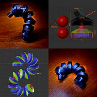
The size of the screws cannot be less than the length necessary for the assembly of the two halves of the external bodies ringed between the two spheres, but it can be easily greater, for special needs (it must be considered that extreme angles are covered with a single joint and with more than one in series, contosional maneuvers are made, if necessary), so maybe for someone even just one may be enough, but with a longer screw, perhaps to be associated with one or more twins upright frontally on a truss made with forms. Or you can mount more joints in series for the third, fourth and fifth hands ... the limit is only the imagination, (see pictures
We come to the tolerances: as soon as they are molded they will be hard to screw and the balls will move very little smoothly and that is why I talked about the running-in phase.
For versions 1.0 and 1.5 I recommend an assembly of the two shells, to be screwed and unscrewed several times, until they become smoothly flowing threads and I suggest to clean the threads at each step, because the dust tends to seize and once cleaned to lubricate slightly before screwing it back on (it will only take until they have dissolved obviously, a matter of a minute).
Once the threads have been loosened, you can insert the spheres with the axes mounted and do a lot of gymnastics, progressively increasing the friction, until the steps of the print layers settle, enough, the rest of the fluidity will come with time. If you make chains of more joints, it will be more complicated at first, I have them broken in and then I coupled them.
Version 2.0 is a little more complicated to assemble due to the fact that the printing of the threads horizontally is more critical and to guarantee an effective seal it must be molded more "tightly", so you will find the work of first coupling the threads extremely hard. , but still feasible and which will guarantee reliable, robust and smooth threads when the procedure is completed.
Another problem of horizontal printing without supports is that the upper parts of the sphere (shell) are much dirtier than in vertical printing, so when you insert the sphere to be run in the walls to be run in, you will not be able to screw the sealing ring of the two half, on the side of the sphere. this is why the assembly and running-in tool comes into play which will settle on the pieces to be run in, even if at the end of running in, it will not be able to guarantee a good seal, but you will only need it for the assembly and running in of the ball and of the walls and then you will insert the regular ring nut, so even just one could be enough to print for all the joints you will make.
In short, as announced, the work is more but then the size / performance ratio will reward the sacrifice of those who want to face it.
Fundamental for all versions is to ensure that the two halves of the sphere are breaded straight on the screw, because otherwise they will not approach well and the sphere will not be regular, creating various problems and in extreme cases, compromising and preventing operation.
If in screwing and unscrewing they loosen too much, so much to turn on the finished arm, annoying the accuracy, you can put a drop of superglue that will restore the brake on the axle, but which will not prevent disassembly if necessary.
To manage the assembly of the spheres on the axes, I do not recommend the use of tools that can damage them, I use a piece of the same rubber that I use to make the discs to put in the core and my hands (perhaps folded if too thin), holding the other side of the metal screw with the pliers.
However, for the whole assembly it is intuitive, especially for those accustomed to using third hands and other related tools.
In any case, for any need, write to me and the same also applies to any suggestion or advice.
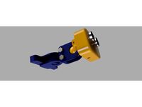
For version 3.0 the speech is separate: it is a completely plastic version, with some limitations in the bending angles that go down to about 25 + 69 degrees, but thanks to the printing made so that the resistances are greater where they are needed, the performance remain good. The great advantage of this version is the ease of construction and assembly, which make it more friendly for those who do not want to do too much post-print DIY, just be careful to correctly couple the two halves of the balls so that the thread is correct, because they are two couples and not four twins.
there remains only the need for the rubber disc for the core and the running-in procedure, but in a more minor way.
The threads of version 1.0 and version 3.0 in the external shells are the same, as are the internal balls, so that you can also make mixed couplings between the versions, if necessary, for upgrades or variations over time.
There will probably be upgrades and variants for this version.
As mentioned at the beginning, everyone can choose the version he prefers for the characteristics that he thinks are most important.
We come to the modular structure, I don't think there is much to say about what to do with it and how to do it, as you will choose it and choose to print the pieces you will need.
In the pictures, a small example of what can be done.
The tips for printing are to use the orientations used in the slicer images and not to use supports for the inside of the female threads, otherwise you will be in trouble.
As for the assemblable bases, there are three tolerance versions which will guarantee you can choose the coupling hardness you want and manage everything based on the characteristics of your printers.
Nothing prevents you from mixing the tolerances to find intermediate hardness values.
As for the elastic tweezers, the cylinder that is together with the print must be forced into the space in the tail and serves to increase the spring load.
If I see that it will be necessary or something else comes to mind, I will bring edit to this explanation.
I printed everything with 0.2mm layers in PLA without difficulty, but no one forbids using thinner layers (just in case let me know what changes).
A small final note: the logo you find on the joints is that of Blender, the program I used to make them, to which it seemed the least I could do to dedicate them to it, with the hope that it will also make a mini-mini contribution to its ever-increasing diffusion.
Greetings to all.
Edit 20/02/2021
Given the good resistance of the horizontal print that is beyond my expectations, I added a new pair of axes and balls for the 3.0 joint version that extends the angle to 35+69 degrees, so that the difference in terms of bend with versions 1.0, 1.5 and 2.0 it is minimal and can be useful to many for less force demanding uses.
I have also added some couplers for the axes in plastic and metal, so that you can interface the 3.0 also with the 2.0 and doubles the possibility of interfacing with the versions 1.0 and 1.5.
Since the shaft is smaller I will have the possibility to increase the 69 degrees and get close to 90 degrees, with a small modification to the shell, and as soon as it becomes available I will update it, presenting the whole joint as version 3.1.
Greetings to all
Edit 20/02/2021
I uploaded version 3.1. The bend angles are now 35+85 degrees, so the difference with the "metal" versions in terms of mobility is minimal, but the advantage in terms of ready to use is a lot.
I suggest a little care and attention in the running-in phase of the balls, because it is possible that the necessary forces are very close to the maximum load that the axis can withstand, so if you proceed in small increments there are no problems, but if you if you want to go a little too fast you risk breaking or weakening the axis, compromising the final yield. In any case, if you have problems you can always reprint only the spheres with the axes, which are the ones I had put as an upgrade.
Greetings to all
Edit 21/02/2021
I added a new axis in version 3.2 (I will also put the stl bundle of all the joint in version 3.2) compatible with versions 3.0 and 3.1 (in this case the shells are just the same) which optimizes the distance between the joints.
It has the same features as version 3.1 (35+85 degrees).
I tried to make the most of the available space, in terms of workable plastic without breaking, by directly threading the inside of the hemispheres.
The thread guarantees an optimal seal, despite the dimensions, but obviously everything must be seen in the context of the possible forces on that type of axis.
For the first assembly (even if only in replacement of version 3.1 or 3.0 if you want), you have to couple and run in the thread (a bit like it happened in version 2.0 or in general) because it is very tight tolerance and to do so, if you have a shell already run in, I suggest to insert it and mount the entire joint well tightened, so that the axis has the thread well aligned.
once the axis is coupled and aligned, it is necessary to make the half sphere with the through hole turn over it, sometimes, at least until the threads are well run in. In this process be careful because the print on the long part of the axis seems to be very weak to twist, so you have to proceed in small increments and go back, cleaning and lubricating the thread.
When the coupling is complete, even with the second half of the sphere (but it will be easy, because the first will have already done all the work), you can insert the female sphere in the other half of the joint and you will be ready to assemble it.
This version will always appear as two halves ringed on the axis between the spheres, so to be mounted you will have to print a version 3.1 or 3.0, which foresees the interfaces with the rest and put the two halves at the end of the chain created with version 3.2 ( or with a single if you prefer).
I will see if to create a direct interface for version 3.2, but for the moment I think it is not a good idea, because I am afraid that it is too fragile if coupled with something rigid and not another joint.
But fundamentally it is not the few millimeters of a more robust interface, like the previous ones that make the difference, the important thing is to have optimized the length in relation to the bend, in the whole chain.
The limit of the forces that can be applied and supported remains present, compared to the previous versions, but also in this case by losing something you gain something else, so this is another possibility of choice and adaptation to the preferences and needs of each.
Greetings to all
Link to Low Profile Joint:https://www.thingiverse.com/thing:4781065
Starting from the joint, which is the most elaborate part of the system, you can see that there is an evolution in the model, but each version has some features that are worth considering to see which one suits the needs best.
In addition to the structural and performance differences, there are also differences in the work required for assembly.
Versions 1.0 and 1.5 are similar for the assembly procedure and differ in load capacities, which are obviously greater in version 1.5 which is slightly larger.
Version 2.0 is an evolution in which I tried to exploit the greater resistance of the printed material in the direction of the effort it has to support instead of with the perpendicular layers and thanks to this system I was able to make a joint that is resistant as, if not of more than version 1.5, but with dimensions smaller than 1.0.
The price to pay for version 2.0 is more work required for assembly.
All versions need a running-in period, and in all versions the concept of tolerance is managed differently, but always aimed at ensuring that after running-in the necessary clutches are the ones needed, as well as being continuous through the load placed with the tightening or loosening the two external parts that will compress the balls on the two braking pads (as well as on their own walls).
At the heart of the system there is the element that keeps the clutch modulation high and guarantees a prolonged duration over time, after running in. this element consists of a rubber disk, which can be obtained from any inner tube of a wheel or from any other part that has that type of rubber (even a piece made from an elastic has the same characteristics and with an elastic as those of 5 or 10mm wide, disks are obtained for a long time).
The thickness of the rubber needed will vary over time and will allow you to recalibrate the clutch every time it becomes impossible to increase it simply by turning the bodies, but thanks to this you will always have an effective joint, and thanks to the elasticity of the rubber the thrust will continue. to exist even with the consumption of plastic requiring a less frequent recalibration, with the effect that will increase in duration over time in a proportional way to the coupling of the parts that rub.
Obviously, the fluidity of the movement will also increase over time.
To obtain the performance and keep the dimensions small, not only plastic can be used, but metal must be used: the axes that fit into the balls are 3mm screws without the heads, which can be obtained from simple screws of length suitable or by threaded bars, always cut into parts of the necessary and desired length.
The assembly work therefore consists in obtaining the rubber and the screws and in cutting everything to size and then screwing them on the spheres (which are cut in half for an optimal print).
The size of the screws cannot be less than the length necessary for the assembly of the two halves of the external bodies ringed between the two spheres, but it can be easily greater, for special needs (it must be considered that extreme angles are covered with a single joint and with more than one in series, contosional maneuvers are made, if necessary), so maybe for someone even just one may be enough, but with a longer screw, perhaps to be associated with one or more twins upright frontally on a truss made with forms. Or you can mount more joints in series for the third, fourth and fifth hands ... the limit is only the imagination, (see pictures
We come to the tolerances: as soon as they are molded they will be hard to screw and the balls will move very little smoothly and that is why I talked about the running-in phase.
For versions 1.0 and 1.5 I recommend an assembly of the two shells, to be screwed and unscrewed several times, until they become smoothly flowing threads and I suggest to clean the threads at each step, because the dust tends to seize and once cleaned to lubricate slightly before screwing it back on (it will only take until they have dissolved obviously, a matter of a minute).
Once the threads have been loosened, you can insert the spheres with the axes mounted and do a lot of gymnastics, progressively increasing the friction, until the steps of the print layers settle, enough, the rest of the fluidity will come with time. If you make chains of more joints, it will be more complicated at first, I have them broken in and then I coupled them.
Version 2.0 is a little more complicated to assemble due to the fact that the printing of the threads horizontally is more critical and to guarantee an effective seal it must be molded more "tightly", so you will find the work of first coupling the threads extremely hard. , but still feasible and which will guarantee reliable, robust and smooth threads when the procedure is completed.
Another problem of horizontal printing without supports is that the upper parts of the sphere (shell) are much dirtier than in vertical printing, so when you insert the sphere to be run in the walls to be run in, you will not be able to screw the sealing ring of the two half, on the side of the sphere. this is why the assembly and running-in tool comes into play which will settle on the pieces to be run in, even if at the end of running in, it will not be able to guarantee a good seal, but you will only need it for the assembly and running in of the ball and of the walls and then you will insert the regular ring nut, so even just one could be enough to print for all the joints you will make.
In short, as announced, the work is more but then the size / performance ratio will reward the sacrifice of those who want to face it.
Fundamental for all versions is to ensure that the two halves of the sphere are breaded straight on the screw, because otherwise they will not approach well and the sphere will not be regular, creating various problems and in extreme cases, compromising and preventing operation.
If in screwing and unscrewing they loosen too much, so much to turn on the finished arm, annoying the accuracy, you can put a drop of superglue that will restore the brake on the axle, but which will not prevent disassembly if necessary.
To manage the assembly of the spheres on the axes, I do not recommend the use of tools that can damage them, I use a piece of the same rubber that I use to make the discs to put in the core and my hands (perhaps folded if too thin), holding the other side of the metal screw with the pliers.
However, for the whole assembly it is intuitive, especially for those accustomed to using third hands and other related tools.
In any case, for any need, write to me and the same also applies to any suggestion or advice.
For version 3.0 the speech is separate: it is a completely plastic version, with some limitations in the bending angles that go down to about 25 + 69 degrees, but thanks to the printing made so that the resistances are greater where they are needed, the performance remain good. The great advantage of this version is the ease of construction and assembly, which make it more friendly for those who do not want to do too much post-print DIY, just be careful to correctly couple the two halves of the balls so that the thread is correct, because they are two couples and not four twins.
there remains only the need for the rubber disc for the core and the running-in procedure, but in a more minor way.
The threads of version 1.0 and version 3.0 in the external shells are the same, as are the internal balls, so that you can also make mixed couplings between the versions, if necessary, for upgrades or variations over time.
There will probably be upgrades and variants for this version.
As mentioned at the beginning, everyone can choose the version he prefers for the characteristics that he thinks are most important.
We come to the modular structure, I don't think there is much to say about what to do with it and how to do it, as you will choose it and choose to print the pieces you will need.
In the pictures, a small example of what can be done.
The tips for printing are to use the orientations used in the slicer images and not to use supports for the inside of the female threads, otherwise you will be in trouble.
As for the assemblable bases, there are three tolerance versions which will guarantee you can choose the coupling hardness you want and manage everything based on the characteristics of your printers.
Nothing prevents you from mixing the tolerances to find intermediate hardness values.
As for the elastic tweezers, the cylinder that is together with the print must be forced into the space in the tail and serves to increase the spring load.
If I see that it will be necessary or something else comes to mind, I will bring edit to this explanation.
I printed everything with 0.2mm layers in PLA without difficulty, but no one forbids using thinner layers (just in case let me know what changes).
A small final note: the logo you find on the joints is that of Blender, the program I used to make them, to which it seemed the least I could do to dedicate them to it, with the hope that it will also make a mini-mini contribution to its ever-increasing diffusion.
Greetings to all.
Edit 20/02/2021
Given the good resistance of the horizontal print that is beyond my expectations, I added a new pair of axes and balls for the 3.0 joint version that extends the angle to 35+69 degrees, so that the difference in terms of bend with versions 1.0, 1.5 and 2.0 it is minimal and can be useful to many for less force demanding uses.
I have also added some couplers for the axes in plastic and metal, so that you can interface the 3.0 also with the 2.0 and doubles the possibility of interfacing with the versions 1.0 and 1.5.
Since the shaft is smaller I will have the possibility to increase the 69 degrees and get close to 90 degrees, with a small modification to the shell, and as soon as it becomes available I will update it, presenting the whole joint as version 3.1.
Greetings to all
Edit 20/02/2021
I uploaded version 3.1. The bend angles are now 35+85 degrees, so the difference with the "metal" versions in terms of mobility is minimal, but the advantage in terms of ready to use is a lot.
I suggest a little care and attention in the running-in phase of the balls, because it is possible that the necessary forces are very close to the maximum load that the axis can withstand, so if you proceed in small increments there are no problems, but if you if you want to go a little too fast you risk breaking or weakening the axis, compromising the final yield. In any case, if you have problems you can always reprint only the spheres with the axes, which are the ones I had put as an upgrade.
Greetings to all
Edit 21/02/2021
I added a new axis in version 3.2 (I will also put the stl bundle of all the joint in version 3.2) compatible with versions 3.0 and 3.1 (in this case the shells are just the same) which optimizes the distance between the joints.
It has the same features as version 3.1 (35+85 degrees).
I tried to make the most of the available space, in terms of workable plastic without breaking, by directly threading the inside of the hemispheres.
The thread guarantees an optimal seal, despite the dimensions, but obviously everything must be seen in the context of the possible forces on that type of axis.
For the first assembly (even if only in replacement of version 3.1 or 3.0 if you want), you have to couple and run in the thread (a bit like it happened in version 2.0 or in general) because it is very tight tolerance and to do so, if you have a shell already run in, I suggest to insert it and mount the entire joint well tightened, so that the axis has the thread well aligned.
once the axis is coupled and aligned, it is necessary to make the half sphere with the through hole turn over it, sometimes, at least until the threads are well run in. In this process be careful because the print on the long part of the axis seems to be very weak to twist, so you have to proceed in small increments and go back, cleaning and lubricating the thread.
When the coupling is complete, even with the second half of the sphere (but it will be easy, because the first will have already done all the work), you can insert the female sphere in the other half of the joint and you will be ready to assemble it.
This version will always appear as two halves ringed on the axis between the spheres, so to be mounted you will have to print a version 3.1 or 3.0, which foresees the interfaces with the rest and put the two halves at the end of the chain created with version 3.2 ( or with a single if you prefer).
I will see if to create a direct interface for version 3.2, but for the moment I think it is not a good idea, because I am afraid that it is too fragile if coupled with something rigid and not another joint.
But fundamentally it is not the few millimeters of a more robust interface, like the previous ones that make the difference, the important thing is to have optimized the length in relation to the bend, in the whole chain.
The limit of the forces that can be applied and supported remains present, compared to the previous versions, but also in this case by losing something you gain something else, so this is another possibility of choice and adaptation to the preferences and needs of each.
Greetings to all
Link to Low Profile Joint:https://www.thingiverse.com/thing:4781065
Similar models
thingiverse
free
Joint (Low Profile Ball Joint) by simonwebnet
... can integrate.
i thank and greet everyone.
link to 3d modular system and other joints:
https://www.thingiverse.com/thing:4768067
thingiverse
free
HC-SR04 Balljoint Case with two balljoints by Divergentti
...you can tighten with iso m5 screws. parts are similar for all joints, so, you may have many more...
thingiverse
free

Ender 3 Camera mount with lockable ball joints by Creappie
...my printer).
an m5 screw is required if you want to tighten the mount to the ender casing. the m5 thread will already be printed.
cults
$12

Jeeg Berserk
... printing of pieces with less contact surface on the printing bed, the use of a raft base for the piece's adhesion is a must.
thingiverse
free

Car holder for note 3 with ball joint by ephestione
...need for a threaded surface.
surely enough, printing it is bothersome as it needs supports, either way you place it on the plate.
thingiverse
free

Ball Socket Joint Bracelet by anverx
...it to work! https://www.youtube.com/watch?v=mfwnmxuzfdk
these joints have about 180 of freedom around one axis plus 360 rotation.
thingiverse
free

ball joint massager turning spheres 3 axis bearing by EgemenErtem
... ball joint and a 3 axis bearing.
sphere_bearing4.1 is a good massager.
when you roll shere_bearng4.1 on your back you feel good.
thingiverse
free

Cerambot Extruder Piston
...s piston.
i will create an updated version for an rubber o-ring if i find one in these dimensions. so this is a work in progress.
thingiverse
free

smartphone holder with clamp and ball joint modified by Drexen29
...nt adapter requires supports under the flat section of the thread and it being flat doesn't affect its ball joint capability.
thingiverse
free

Added a univeral ball joint to the original file by swehugin
...w holes and a thread for assembly. now you can 3dprint the entire thing and just add some metal screws and bolts.
happy printing!
Simonwebnet
thingiverse
free

Microphone kit by simonwebnet
....html?spm=a2g0s.9042311.0.0.1a264c4dxs7ou8
https://it.aliexpress.com/item/4000089334876.html?spm=a2g0s.9042311.0.0.27424c4dy38unl
thingiverse
free
Joint (Low Profile Ball Joint) by simonwebnet
... can integrate.
i thank and greet everyone.
link to 3d modular system and other joints:
https://www.thingiverse.com/thing:4768067
Joint
3d_ocean
$29
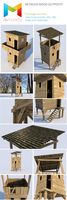
Realistic Wooden Outposts
...very detailed realistic outposts built of wood and metal joint, medieval style. game ready. included files : package includs...
3ddd
$1
PENTA Joint
...penta joint
3ddd
penta
http://www.lampcommerce.com/en/catalogue/brands/penta-light/joint-floor-lamp
3ddd
$1

GRAMERCY HOME - INDUSTRIAL JOINT TABLE LAMP TL016-1-BRS
...strial joint table lamp tl016-1-brs
3ddd
gramercy home
gramercy home
industrial joint table lamp
tl016-1-brs
www.gramercy-home.ru
3ddd
$1

Лампа Timothy Oulton - Knuckle Joint Table Lamp
... knuckle joint
лампа от timothy oulton, стек не свернут.
размеры от производителя:
длина: 35 см
ширина: 35 см
высота: 63 см
3ddd
$1
GRAMERCY HOME - INDUSTRIAL JOINT FLOOR LAMP FL016-1-ABG
...strial joint floor lamp fl016-1-abg
3ddd
gramercy home
gramercy home
industrial joint floor lamp
fl016-1-abg
www.gramercy-home.ru
3d_ocean
$15

RobotX-JV1.0 Rigged
...robotx-jv1.0 this is a full rig robot model. no joint and animation. for the rigging system is the ik...
3d_ocean
$29

Dibot - Utility Robot
...utility bot of minimalistic aesthetics with unique rotating forearm joint. it is designed to be extremely tough and powerful,...
3d_ocean
$6

Truss Model Set
...models, including the joint pieces, including the tjoints and ljoint, ...
3d_ocean
$12

Exploded Half Axle
...axle 3docean axle chassis constant cv drive engine gearbox joint part planetary shaft velocity wheel an exploded half axle...
3d_ocean
$5

Engineering Fastner Pack
...engineering fastner pack 3docean bolt engine engineering fastner joint pack parts screw tool pack of engineering...
Ball
3d_export
$5

Football ball 3D Model
...football ball 3d model
3dexport
football ball 3d model hitman47 72496 3dexport
3d_export
$5
Crystall Ball on Golden Stand 3D Model
...crystall ball on golden stand 3d model
3dexport
crystall ball on golden stand 3d model angelikwingz 38432 3dexport
3d_export
$5
Tennis ball 3D Model
...tennis ball 3d model
3dexport
tennis ball 3ds max obj
tennis ball 3d model clio3d 64198 3dexport
3d_export
$89

Old Billiard Table 3D Model
...billiard table 3d model 3dexport table billiard pool stick ball bar pub game sport play snooker wood tournament old...
3d_export
$5

Pokeball Repeat Ball 3D Model
...pokeball repeat ball 3d model
3dexport
pokeball pokemon repeatball
pokeball repeat ball 3d model floydust4 75159 3dexport
3d_export
$5

Pokeball Sammys Old Ball 3D Model
...ammys old ball 3d model
3dexport
pokeball pokemon sammy's old ball
pokeball sammys old ball 3d model floydust4 75162 3dexport
3d_export
$15
Low Poly Mini Golf Hole C4H2 3D Model
...model 3dexport mini golf minigolf mini-golf putt-putt putt club ball hole course goal flag par sport sports low low...
3d_export
$15
Low Poly Mini Golf Hole C4H4 3D Model
...model 3dexport mini golf minigolf mini-golf putt-putt putt club ball hole course goal flag par sport sports low low...
3d_export
$15

Low Poly Mini Golf Hole C4H18 3D Model
...model 3dexport mini golf minigolf mini-golf putt-putt putt club ball hole course goal flag par sport sports low low...
3d_export
$59

HiPoly Cricket Player Batter 3D Model
...cricket entertainment helmet sport character man glove gloves bat ball protection seams india british australia hipoly cricket player batter...
Double
3ddd
$1
IKEA Svartsjon Double hook
...ikea svartsjon double hook
3ddd
ikea , крючок
двойной крючок ikea
3ddd
$1

MERCANTILE DOUBLE VANITY SINK
...а , бра , зеркало
mercantile double vanity sink
3ddd
$1

Kohler Triton® Shelf-back double wristblade lever handle sink faucet with loose-key stops
... смеситель
медицинский (хирургический) смеситель
height 8-7/16"
length 7-5/8"
width 8"
k-7308-5a-cp
3ddd
$1

ClassiCon Double-X
...classicon double-x
3ddd
classicon
classicon double-x modern table
3ddd
$1
Vespa
...end table crafted from solid and veneered mahogany with double 'v' detailing. (shown in java cafe varnish/renaissance gold) w65...
3ddd
$1

Double palm trees in a pot
...uble palm trees in a pot
3ddd
пальма , горшок
double palm trees in a pot with brass foot
3ddd
$1
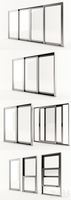
Generic Windows
...generic windows 3ddd окно generic, double glass...
3d_ocean
$25

Container shipping House double floor
...l is fully textured with all applied materials: - textures formats: tif (x4) - textures size: x1024 (x1), x2048 (x3) - materia...
3d_ocean
$5
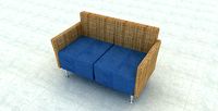
Double Sofa
...double sofa
3docean
double sofa made by fabric, wood & ss leg
3ddd
$1

Leather double bed
...leather double bed
3ddd
leather double bed, dimension: 180x210 cm
System
3d_export
$23

Anesthesia Delivery System 3D Model
...h healing interior medicine 3ds max vray mental ray obj fbx detailed 3d
anesthesia delivery system 3d model cgaxis 91625 3dexport
3d_export
$26

Pakistan HatfIII SRBM Missile 3D Model
...ghaznavi missile rocket vehicle military short range ballistic guided system projectile nuclear weapon game ready 3ds cob pakistan hatfiii...
3d_export
$29
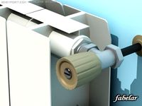
Radiator 2 3D Model
...2 3d model 3dexport radiator aluminium heat heating column system cold steam building pipe boiler people living room vray...
3d_export
$79

Sega Megadrive 3D Model
...sega megadrive 3d model 3dexport sega megadrive mega drive system arcade console vintage old retro photorealistic toy computer people...
3ddd
$1

BESTÅ system Combinations with pictures
... 590.896.08
ящики и дверцы закрываются мягко и бесшумно, благодаря встроенным демпферам
картины художника майкла аарона уильямса
3ddd
$1
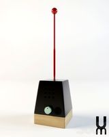
CRAFT SYSTEM UM PROJECT
...ddd
craft system , um project , lamp
+ max 2011
3ddd
$1
Aviation PRO
...aviation pro 3ddd oligo , aviation http://www.oligo.de/en/products/systemluminaires/prod/st-aviation-pro-1.html ...
3ddd
$1
Три ковра 4
...- цвета: зеленый, тёмно-серый, бежевый внимание!!! для корректного отображения: system units setup - millimeters rendering > effects > hair...
3ddd
$1

Artisan media cabinet with wall mirror
...shelves behind each of the three doors. open slat system back allows easy access to component wiring. ссылка на...
3ddd
$1

Ezio Bellotti
...bellotti 3ddd ezio bellotti , кресло ezio bellotti offices system art. 2017 750х850 мм. h=115...
Support
3d_export
$12

Walking Canes 3D Model
...canes cane stick sticks assistive crutch crutches hiking camping support disabled staff aid balancing trekking poles gentlemen classic old...
3d_export
$50

Fast Food Restaraunt Set 3D Model
...restaraunt 3d models tables chair seats pan tray bottles support boxes interiors furniture fast food restaraunt set 3d model...
3ddd
$1

Neverending Glory
...the leadership of mozart himself. through this collection avid supportrs and lovers of stories and simplicity can acquire a...
3d_ocean
$2
Grassydirt
...2k dirt grassy ground textures grassydirt cg textures tileable support include : normal map + specular...
3d_ocean
$2
Deadgrass
...dead? i hope you come back to life! tileable supportd! have any problem? contact...
3d_ocean
$7
Substance Textures 2-Pack
...need to open them in unity, unreal, any other supportd game engine or substance designer itself) create hundreds of...
3d_export
$10
Bookend 3D Model
...bookend 3d model 3dexport bookend support books end bookshelf library sheetmetal metal home decor decoration...
3d_ocean
$2
Cementwall
...be careful! , cement walls were very sharp! tileable support have any problem? contact...
3ddd
$1
LEMA 3-POD
...tripod: a continuous symbol in chrome plated steel which support a plane—rectangular, round or drop-shaped in glass, wood, or...
3ddd
$1
Flexform Mood Drop
...by felxform/mood from drop collection. quad single model mesh. support ...