Thingiverse
JGAurora Z603S Infrared Autobed Level Modification by Waggster
by Thingiverse
Last crawled date: 3 years, 1 month ago
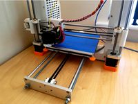
JG Aurora Z603S Infrared sensor upgrade
https://youtu.be/L8FqyaKwRao
This only works for the later GREEN motherboard.
WARNING WARNING
MAKE SURE YOU DOUBLE CHECK YOUR CONNECTIONS
POSITIVE to POSITIVE
NEGATIVE to NEGATIVE
SIGNAL to SIGNAL
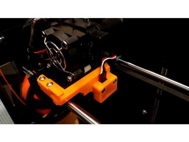
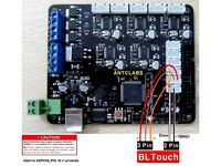
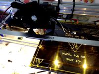
I soldered an extra 3 pin socket to my green motherboard (PIN 18). This is where the IR sensor is plugged in. Please check the image for the correct connection. The original opto Z min endstop has been disabled in the firmware as I intend to use it as a filament sensor input in the future. You can if you wish plug your new IR sensor into the Z min to save soldering anything. If you do this then you will need to change the allocated #define Z_MIN_PIN in the PINS_Z603s sketch back to pin 19.
WARNING WARNING
Description
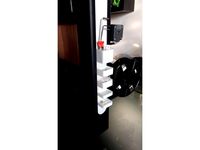
Autobed level addition to the JG Aurora Z603S 3D printer.
Items you will require
Infrared sensor - https://miscsolutions.wordpress.com/mini-height-sensor-board/
3 wire servo extension lead (2 x 1m in length)
Files included
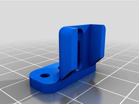
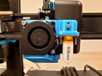
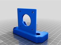
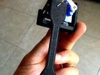
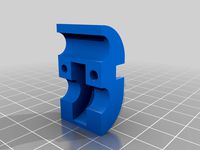
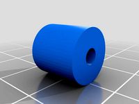
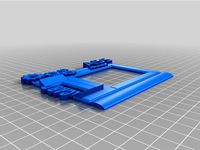
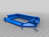
Mount STL
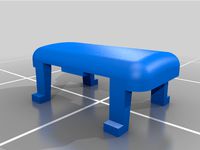
Cover
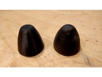
New X endstop trigger
Firmware 1.1.8 Marlin
To do this modification you will need to update the main board's firmware. You will need to update using the Arduino IDE software.
There are plenty of youtube videos showing you how to do this, just search for update marlin via arduino ide.
You will need to open your machine up and feed the 3 wire connector around the machine. The sensor uses a new 3 pin connector which I soldered too on the main board. If you do not want to do this then you can alter the firmware to use the Z minimum endstop connector. See above for changing to the pins info in the firmware required.
The current z endstop needs to be removed. Just unscrew it from the side frame and hide it below. You can always go back then if needed.
I've already configured the firmware to use this sensor, so you will only need to flash it. I have enabled the eeprom on the board, so you can save
bed levels.. but I would level at the start of every print just to be safe.
To level, you will need to add some gcode lines to your start gcode script. There is normally a tab / section in your software.. the lines you need to add are,
M851 Z-3.1 ; Z Offset
M500 ; Save to Eeprom
G28 ; Home
G29 ; Level bed
etc...
The Z offset can be set above. Z-1.0 = 1mm.. so if you want to lower the head then you would do..
M851 Z-1.2 ; Z Offset
This would then be 0.2mm closer than before.
Let me know how you get on.. Any questions please ask away and don't forget to like this :-)
I would also recommend adding the following to your gcode start / stop script in your preferred printing program.
START SCRIPT
M851 Z-3.1 ; Z Offset <--- NOTE you will need to change this value
M500 ; Save to Eeprom
G28 ; home all axes
G29 ; Level bed
G1 X10 Y10 F9000 ; get ready to prime
G1 Z0.3 F6000
G92 E0 ; reset extrusion distance
G1 X240 Y10 E24 F2000
G1 X250 Y10 F180
G1 X260 Y10 F5000
END GCODE
G1 X0 Y180 F3000 ; Move bed / head
G1 Z170 F3000 ; Move bed / head
M106 S0 ; turn off cooling fan
M104 S0 ; turn off extruder
M140 S0 ; turn off bed
M84 ; disable motors
Then disable SKIRT or BRIM as you wont need it anymore.
https://youtu.be/L8FqyaKwRao
This only works for the later GREEN motherboard.
WARNING WARNING
MAKE SURE YOU DOUBLE CHECK YOUR CONNECTIONS
POSITIVE to POSITIVE
NEGATIVE to NEGATIVE
SIGNAL to SIGNAL
I soldered an extra 3 pin socket to my green motherboard (PIN 18). This is where the IR sensor is plugged in. Please check the image for the correct connection. The original opto Z min endstop has been disabled in the firmware as I intend to use it as a filament sensor input in the future. You can if you wish plug your new IR sensor into the Z min to save soldering anything. If you do this then you will need to change the allocated #define Z_MIN_PIN in the PINS_Z603s sketch back to pin 19.
WARNING WARNING
Description
Autobed level addition to the JG Aurora Z603S 3D printer.
Items you will require
Infrared sensor - https://miscsolutions.wordpress.com/mini-height-sensor-board/
3 wire servo extension lead (2 x 1m in length)
Files included
Mount STL
Cover
New X endstop trigger
Firmware 1.1.8 Marlin
To do this modification you will need to update the main board's firmware. You will need to update using the Arduino IDE software.
There are plenty of youtube videos showing you how to do this, just search for update marlin via arduino ide.
You will need to open your machine up and feed the 3 wire connector around the machine. The sensor uses a new 3 pin connector which I soldered too on the main board. If you do not want to do this then you can alter the firmware to use the Z minimum endstop connector. See above for changing to the pins info in the firmware required.
The current z endstop needs to be removed. Just unscrew it from the side frame and hide it below. You can always go back then if needed.
I've already configured the firmware to use this sensor, so you will only need to flash it. I have enabled the eeprom on the board, so you can save
bed levels.. but I would level at the start of every print just to be safe.
To level, you will need to add some gcode lines to your start gcode script. There is normally a tab / section in your software.. the lines you need to add are,
M851 Z-3.1 ; Z Offset
M500 ; Save to Eeprom
G28 ; Home
G29 ; Level bed
etc...
The Z offset can be set above. Z-1.0 = 1mm.. so if you want to lower the head then you would do..
M851 Z-1.2 ; Z Offset
This would then be 0.2mm closer than before.
Let me know how you get on.. Any questions please ask away and don't forget to like this :-)
I would also recommend adding the following to your gcode start / stop script in your preferred printing program.
START SCRIPT
M851 Z-3.1 ; Z Offset <--- NOTE you will need to change this value
M500 ; Save to Eeprom
G28 ; home all axes
G29 ; Level bed
G1 X10 Y10 F9000 ; get ready to prime
G1 Z0.3 F6000
G92 E0 ; reset extrusion distance
G1 X240 Y10 E24 F2000
G1 X250 Y10 F180
G1 X260 Y10 F5000
END GCODE
G1 X0 Y180 F3000 ; Move bed / head
G1 Z170 F3000 ; Move bed / head
M106 S0 ; turn off cooling fan
M104 S0 ; turn off extruder
M140 S0 ; turn off bed
M84 ; disable motors
Then disable SKIRT or BRIM as you wont need it anymore.
Similar models
thingiverse
free
JGAurora A5 Infrared Side Autobed Level modification by Waggster
....
you don't need to change the tft firmware, you won't get any benefit from it as it doesn't support z offset setting
thingiverse
free
JGAurora A5 Infrared Autobed Level modification by Waggster
...s it doesn't support z offset setting
the cover, just slides down onto the mount :-) it didn't look very nice without it.
thingiverse
free
BLtouch mount for Raise3D N2/N2+ by sylus
...org/docs/gcode/g029-mbl.html
z offset to set with you current setup could be set by a script on start gcode as :
m851 z-x.xx
m500
thingiverse
free
Ender-3 Filament Waste Squeegee
...0 y10 f2000.0 ; wipe
g1 x248 y10 f2000.0 ; wipe
g1 z0 x200 y10 f1500.0 ;
m117 printing...
thingiverse
free

Ender 3 V2 Brush mount by SharpSeer
...ed
g1 x5 y20 z0.3 f5000.0 ; move over to prevent blob squish
lastly, rotate the print till it is flat, i have not altered it yet.
thingiverse
free

SN04 Sensor holder for ANET A8 by AUREL_14
...is command: m851 z-x.xx where x.xx is the noted value.
in a terminal, send this command: m500 (to sauve the offset in the eeprom)
thingiverse
free

Ender 2 mainboard display case by usersylvio
...ript:
g28 x0 ; home x axis
m106 s0 ; turn off cooling fan
m104 s0 ; turn off extruder
m140 s0 ; turn off bed
m84 ; disable motors
thingiverse
free
Sunhokey Prusa i4 BLTouch Setup Marlin 1.1.0 RC8 Firmware by Middleman
....
now you are ready to print with the bltouch!
join the prusa i4 facebook group: https://www.facebook.com/groups/573076312852368
thingiverse
free

Repetier auto-level 0.92.9 for DMY3DP-001 (p802m / anet a8 clone) by crazytiti
...need and isp to put the arduino bootloader on your board, then use classic arduino usb upload.
demo :https://youtu.be/xs7vn1hkf7k
thingiverse
free

Arm for auto leveling to reuse Z endstop (with gCode) by clickticnic
...m for auto leveling to reuse z endstop (with gcode) by clickticnic
thingiverse
auto bed leveling arm adapter for reuse z endstop
Z603S
thingiverse
free

z603s Air guide
...z603s air guide
thingiverse
z603s air guide
thingiverse
free

JG Aurora Z603S Tool Holder by xLORDxSIDIUSx
...jg aurora z603s tool holder by xlordxsidiusx
thingiverse
work in progress
tool holder for the jg aurora z603s 3d printer.
thingiverse
free

JG Aurora Z603S Spool Arm XL by xLORDxSIDIUSx
... the spool holder for the jg aurora 3d printer. i found the oem part too small to accept many of the filaments that i purchased.
thingiverse
free

JG AURORA Z-603S - X STEPPER SUPPORT by VisiTor
...jg aurora z603-s - x stepper support jg aurora z603s - x stepper support jgaurora z603-s - x stepper...
Waggster
thingiverse
free
M4 Waggster BLTouch Mount by alc6379
...the fan duct in question took a long time to print, so i just adapted this instead of trying to reprint the duct with an m3 hole.
thingiverse
free
Sidewinder X1 Waggster Mod BLTouch with improved Fan Duct
...fere with the waggster mod for bltouch.
combined the two in tinkercad.
credits should go to the creators of the original desigs.
thingiverse
free

Wanhao Duplicator D7 Stand by Waggster
...ator d7 stand by waggster
thingiverse
a simple design to enable you to lift the d7 up for better airflow to the led cooling fan.
thingiverse
free

Sidewinder X1 - Waggster BLTouch Cover/Shield by HobbyCentre
...e movement in the cover once installed but this does not translate to any additional noise audible over the printer in operation.
thingiverse
free
Sidewinder X1 BMG Wind extruder with Waggster Fan duct for 5015 blower by Steve0211
...e waggster fan duct, for a bmg wind extruder on a artillery sidewinder x1.
remix from : https://www.thingiverse.com/thing:4561356
thingiverse
free
DJI Mavic Air 2 - LED covers by Waggster
... by waggster
thingiverse
these need to be resin printed... designed up as i lost a couple of mine. they are tiny things.... :-)
thingiverse
free
KEF PSW2000 Subwoofer foot by Waggster
...fer but it had one missing foot. so, i designed this one and printed it at 40% infill out of flexible filament.
works great :-)
thingiverse
free
JG Aurora A3 Stable Feet by Waggster
... quality of the jg aurora by making it more stable and reduce the z wobble. no fixings required, the parts just slip underneath.
thingiverse
free

Artillery Sidewinder/Genius Waggster Mod BL Touch Mount With Fan Duct by blinkybill
...there is a place for a nut on the back in case you want to attach the third fan screw although it is not needed.
buy me a coffee:
thingiverse
free

R2D2 Front Logic ports with flat back for single LCD by Waggster
... logic ports with flat back for single lcd by waggster
thingiverse
designed up so they sit flat against a single 4.3 tft screen.
Autobed
thingiverse
free
K8200 autobed leveling by Mitch32
...placer le switch z et le mettre sur le bras modifier
marlin et sclir
et tout est nickelhttp://www.youtube.com/watch?v=uoew-lwr7hu
thingiverse
free
Sunhokey 2015 Autobed leveling by Evros
...ey 2015 autobed leveling by evros
thingiverse
this is my idea of auto bed levelling for sunhokey 2015 model. i hope you like it.
thingiverse
free

Tronxy X5 Autobed-Leveling Kapazitive by oerny18
...xy x5 autobed-leveling kapazitive by oerny18
thingiverse
tronxy x5 to level the bed automaticly.
for sensor :
capacitive 18 (mm)
thingiverse
free

MeCreator 2 Autobed Leveling Sensor Halterung by xXIssiXx
...sender sensor https://www.conrad.de/de/kapazitiver-naeherungsschalter-m12-buendig-pnp-pepperl-fuchs-cbb4-12gh60-e2-v1-156456.html
thingiverse
free

Delta Effector for E3DV6 & 2x 40mm fans with autobed level mount by LSP
...nt by lsp
thingiverse
love this mount that robkar has made. but i need a mount for a autobed level so i like to share it for you
thingiverse
free

Autobed level Prusa i4 Sunhokey by TMMOTORSITALIA
... estrusore e ventola e smontare e riposizionare il convogliatore ventola .
il modello del sensore è lj18a3-8-z/bx 200ma\6-36v dc
thingiverse
free

Tarantula Dual Extruder AutoBed Sensor Mount by jrocket9779
...tula dual extruder autobed sensor mount by jrocket9779
thingiverse
just rotate bracket to flat side and scale up to 10 to print.
thingiverse
free

TronXY AutoBed Level Holder by cfscrwed
...
this mounts and replaces the fan shroud and hangs the sensor off the side.
printed on flashforge dream using pla @ 210 bed @ 60
thingiverse
free

Creatr HS - Probe holder - Autobed leveling by alex-muc
...creatr hs - probe holder - autobed leveling by alex-muc
thingiverse
this is a 18mm probe holder for the creatr hs from leapfrog.
thingiverse
free

Dual E3D v7 Hotend Mount with autobed leveling by Spider69
...mount with autobed leveling by spider69
thingiverse
based on http://www.thingiverse.com/thing:364650 with 18mm capacitive sensor
Jgaurora
thingiverse
free
accessorio JGAURORA by raffaelemobile
...accessorio jgaurora by raffaelemobile
thingiverse
stampato con jgaurora a3s riempimento 10% pareti 0.8
thingiverse
free
JGAurora Filament Guide by coogle
...jgaurora filament guide by coogle
thingiverse
a simple filament guide for the jgaurora printer
thingiverse
free
JGAURORA A5 z stabilizer
...jgaurora a5 z stabilizer
thingiverse
jgaurora a5 z stabilizer
roller size 22mm
thingiverse
free

LED Light for JGAurora A5
...led light for jgaurora a5
thingiverse
a light for jgaurora a5 made with led stripes and l-profile as a holder.
thingiverse
free
spring guid Jgaurora A5 by delichoc45
...spring guid jgaurora a5 by delichoc45
thingiverse
guide ressort jgaurora a5
thingiverse
free
JGAurora A5 side toolbox by P_Erhard
...jgaurora a5 side toolbox by p_erhard
thingiverse
toolboxes that clip into the side of the jgaurora a5 frame.
thingiverse
free
JGAURORA A5s Display Cover by nethunter27
...jgaurora a5s display cover by nethunter27
thingiverse
this is a jgaurora a5s displaycover.....from my printer,and my design!
thingiverse
free

Calibration Tool for JGAurora A1
...oon...
visit our jgaurora mkii upgrades group here at thingiverse:https://www.thingiverse.com/groups/jgaurora-mk2-upgrades/things
thingiverse
free
SKR mount for JGAURORA A5S
... hold the skr 1.3 control board to the posts in the jgaurora a5s chassis. holds a 40x10 fan for airflow across driver heatsinks.
thingiverse
free

m8 bowden connector for jgaurora a5 by death4u
...coupler for on the extruder of my jgaurora a5 broke. the original design had m6 and m10 couplers but the jgaurora a5 needed a m8.
Infrared
turbosquid
$2

INFRARED
... available on turbo squid, the world's leading provider of digital 3d models for visualization, films, television, and games.
turbosquid
$26

Infrared Thermometer
...alty free 3d model infrared thermometer for download as blend on turbosquid: 3d models for games, architecture, videos. (1638742)
turbosquid
free

infrared heater
...ee 3d model infrared heater for download as max, fbx, and obj on turbosquid: 3d models for games, architecture, videos. (1712209)
turbosquid
$65

Infrared Thermometer
...odel infrared thermometer for download as blend, fbx, and obj on turbosquid: 3d models for games, architecture, videos. (1613763)
turbosquid
$20

Infrared Thermometer
...infrared thermometer for download as blend, dae, fbx, and obj on turbosquid: 3d models for games, architecture, videos. (1681061)
3d_export
$5

Infrared Heater 3D Model
...infrared heater 3d model
3dexport
heater infrared ufo
infrared heater 3d model pavel234 19550 3dexport
turbosquid
$29

Infrared Medical Thermometer
...nfrared medical thermometer for download as max, fbx, and obj on turbosquid: 3d models for games, architecture, videos. (1553207)
turbosquid
$9

Infrared Thermometer PBR
...l infrared thermometer for download as max, max, fbx, and obj on turbosquid: 3d models for games, architecture, videos. (1577645)
turbosquid
$45

infrared quartz heater
... available on turbo squid, the world's leading provider of digital 3d models for visualization, films, television, and games.
turbosquid
$33

Infrared Thermometer Red
... available on turbo squid, the world's leading provider of digital 3d models for visualization, films, television, and games.
Modification
turbosquid
$12
AKMS (AK47 modification)
... available on turbo squid, the world's leading provider of digital 3d models for visualization, films, television, and games.
turbosquid
$79

BusTransForm - Modif Bus Thailand
...d model bustransform - modif bus thailand for download as obj on turbosquid: 3d models for games, architecture, videos. (1383303)
3d_export
$25

mitsubishi evo 9 modification
...mitsubishi evo 9 modification
3dexport
evo 9 has been modified with a nice and elegant look.
3d_ocean
$25

Dart Vader (modificated helm)
...niforms, as well as anatomical model of the character itself. the model is divided into groups for further editing. primarily ...
turbosquid
$15

FN SCAR-H modification low-poly game ready
...fication low-poly game ready for download as ma, obj, and fbx on turbosquid: 3d models for games, architecture, videos. (1386384)
3d_export
$5

sphere light
...sphere light
3dexport
the socket and light are modifables
3d_export
$5

Fabulous chest
...chest 3dexport fabulous chest for your game or further modification ...
3d_export
free

cold coffee
...cold coffee 3dexport cold coffee can. any required modification will be done at...
3d_ocean
$12

Cartoon Dump or Sand Truck
...already rig low poly modifier still in stack for modification unwrap uvw for material and colour...
3d_ocean
$12

Cartoon Cement Mixer Truck
...already rig low poly modifier still in stack for modification unwrap uvw for material and colour...
Level
design_connected
$11

Levels
...levels
designconnected
one nordic levels computer generated 3d model. designed by form us with love.
design_connected
$7
Level
...level
designconnected
zanotta level shelves and storage computer generated 3d model. designed by arik levy.
turbosquid
$29
level
...ty free 3d model level for download as 3ds, obj, c4d, and fbx on turbosquid: 3d models for games, architecture, videos. (1272856)
turbosquid
$1
level
... available on turbo squid, the world's leading provider of digital 3d models for visualization, films, television, and games.
3d_export
$5

Mario level
...mario level
3dexport
mario level low quality for fun videos
3ddd
$1

LEVELS OF DISCOVERY
...етская мебель "levels of discovery". rab10003 princess mini rocker
кресло-качалка (мини) "принцесса навсегда"
3d_export
$19

level design
...level design
3dexport
you can use this design (level design) in your own game.
turbosquid
$60
Desert level
...squid
royalty free 3d model desert level for download as fbx on turbosquid: 3d models for games, architecture, videos. (1208131)
turbosquid
$15
Transit Level
...quid
royalty free 3d model transit level for download as max on turbosquid: 3d models for games, architecture, videos. (1158112)
turbosquid
$14

Districts Level
...id
royalty free 3d model districts level for download as max on turbosquid: 3d models for games, architecture, videos. (1408410)