Thingiverse
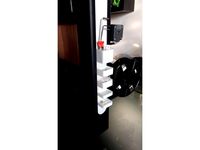
JGAURORA A3S Reference Model by poikilos
by Thingiverse
Last crawled date: 2 years, 10 months ago
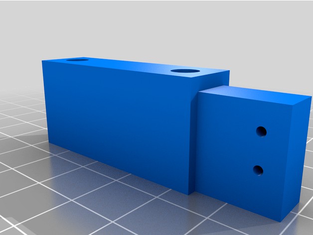
This (JGAURORA A3S V1 Reference Model 1.0) took about 48 hrs. I assume that we must not infringe on JGAURORA's intellectual property by manufacturing clones of the printer. However, I assume you can use it to:
Make mods.
Re-print or change the included stock-style parts in case they fail or you want to improve them (I made STL files of each)
If any stock parts do not have an STL file or they do not fit, please explain the exact problem in a comment, with measurements if possible. See "Print Settings" on this page before printing to try to get it exact!
Hardware
JGAURORA A3S V1
The mainboard says: "MKS Gen L V1.0"
The TFT board says: "MKS TFT28 V3.0"
There is an unoccupied WiFi port.
The serial port is at the bottom middle (and must be disconnected while flashing the mainboard!).
Measurements
The "Measurements" section and subsections apply to the stock parts provided by the manufacturer or exact equivalents.
The blend file uses "left" and "right" to refer to the left and right of the user looking at the front of the 3D printer.
The terms "near and far" are used when looking at the side of the printer to avoid confusion though parts with those labels may be close to each other.
The categories or objects marked "unutilized" are apparently not used from the factory (including the set screw holes on the y axis rail rear mounts!).
The front was perfected by measuring from the screws, measuring to the edge, then measuring the angle (60 degrees). After the (unused) object "body - upper - outer - beveled 16mm before corrected y -4.891" was made, the following changes occurred:
The former angle was 122.125 and the measured angle is 120. The scaling values are dependent on the ratios and were obtained by trial and error (typing each digit and backspacing).
Change "Camera at angle..." to the angle corresponding to the measured angle: -60 (formerly 57.875)
Move inward (to shorten body) by global y 4.891
Move outward by global y -1.0
scale the front edge ring by y .91949 (actually scaled that one by .9195)
Changes 122.125 to 120 or 57.875 to 60.
scale the next edge ring by y .92343
The rotation of the mainboard parts are rotated by 2.125 (to 240, formerly 237.875).
The margin of error for my measurements is apparently +/- .1mm as far as I can tell.
The bottom tapers, perhaps on purpose to be a force fit, or perhaps due to inaccuracy in manufacturing. Therefore, the gantry cutout doesn't visually fit into the slots in the base, but it does in real life since it becomes narrower toward the bottom. The larger depth (global y axis size) is used because the rest of the frame is that size (65.35 mm).
In cases where the factory margin seemed wider or there was uncertainty using digital calipers due to the angle or mechanical tolerances of the calipers (mine have an apparent error rate of about 0.011 on average)), I used the approximate average of multiple points and/or copies of the part or used the nearest measurement that seemed sensible (if the average was close to a round mm figure, nearest quarter mm, or sheet metal gauge).
The shank holes for the z axis motor mounts were incorrect, making the motors stick out by up to ~.84mm below the bottom of the gantry (on the inside part of the bottom-facing face of the left motor).
The motors themselves appear to be 32.35 in height on the z axis.
In the case of the shank holes, modified and corrected shank holes were placed in the model for the z axis motor mounts.
For example, for that shank hole: 32.87 32.35 + 2.74 half of screw head width + .84
However, using a theoretical optimal placement is better using the following measurements:
32.35 motor + 8 8.15 motor mount = 40.5
motor mount: 8 8.15 (screw hole: 4--assume the tap holes are at the halfway mark for the screws through the gantry)
and using the following calculation:40.5 - 8 + 4 = 36.5 center of corrected shank hole from bottom of gantry
32.35 + 8.15 - 4.075 = 36.425 center of corrected shank hole from bottom of gantry (formerly 35.98)
Modding note: To attach a new frame to the bottom of the gantry without modifying the holes, using washers as spacers may be a good idea.
5mm washers of around .84mm and 4mm washers of around .8mm can be found in NINDEJIN's "304 Stainless Steel Hex Socket Head Cap Screws" kit. Some 4mm ones measure thicker but the flat parts measure around .8 or .85, so after deburring or flattening or filing gently they should be adequate. The 5mm ones seem cleaner but some are thicker (but could be filed or pressed to .84mm).
However, thinner spacers may be better since sticking out by .84 may be caused by bending of the frame as the z motor mounts are thin and only fastened from one side!
The margin of error may be up to .5 in some places where there is no way to measure by touch (when the 3D printer is disassembled into only the 3 major sheetmetal-framed components), but whenever possible, some sort of rod is used to reach. The margin of error may still be up to .5 mm or so when a straight measurement is still not possible other than by aligning the part edge and eye with each caliper edge separately.
Many edges are left sharp, so they are extended to their imaginary (unbeveled) edges, so the margin of error may be greater on parts where that is the only source of measurement such as the screen.
This may not be the case anymore since a straightedge was placed against the surface to visualize the sharp corner. The measurement of the depth of the front to the cut on the y axis is 30 mm and that should be within the tolerance of .1mm (The "body - upper - screen plate + protector" model is now 1.0 (instead of 1.5) so the depth of the part that wraps around is 29.
Mainboard
The mainboard texture is for rough clearances only. The mounting posts are measured according to the usual margin of error.
TFT Board
The margin of error for the pixels in the texture are significant since the picture was taken at a slight angle then corrected for perspective and aspect ratio. However, if you look closely, you can see that the bottom of each object is nearly pixel perfect. The top is skewed off to the right slightly. This offset is even noticeable on the screw heads.
The center of the bottom screws are 12 mm from the bottom.
The screw spacing from center to center on the x axis is 44 mm.
The screw spacing from center to center on the y axis is 65 mm.
Sheet metal
The sheet metal standards used below are from https://www.metalsupermarkets.com/sheet-metal-gauge-chart/.
The sheet metal for the body is modeled as 1.518 since that is the closest gauge (16ga).
The sheet metal for the bed mount assembly and other thin sheet metal parts is modeled as 1.214 since that is the closest gauge (18ga).
Similar models
thingiverse
free

TronXY X1 Y axis motor mount (compact) by irritatingsour
...table" mounting point for end-stop switch. mounted with the same t-nuts and screws that are also used with the factory part.
thingiverse
free

PrintNC - X Gantry Cable Chain Mount 2x4" Tubing by pastorhealer
...unter sunk screws (in the aluminum angle) with the nuts at under.
i laid the part on it's side to print and it came out fine.
thingiverse
free
2-Piece Prusa MK2s Y-axis Motor Mount v20 by TOGOMedia
... useful if you have spent the time to square it up, precisely. the 2 halves of the part may be assembled with m3 screws and nuts.
thingiverse
free

Gantry CNC Sliders (KRCNC) by Korrokus
...=2mm.
mounting holes for the mill are for m3.
additional mounting holes for m4 screws to be used with 624vv 4mm v-grove bearings.
thingiverse
free
ADXL345 bracket for Ender gantry by MathiasM74
... material thickness). using the screw hole to secure it to the gantry is optional (and will likely leave a mark).
takes m3 bolts.
thingiverse
free

Printer base clamp and z-axis squaring mount by Westdale3D
...lamp (2 at either end of the y-axis). then the two square mount for z-axis pieces could be fastened the the platform and printer.
thingiverse
free
i3 z-axis-top separator by xoan
...distance between the frame and the smooth rods in to separated points, top and bottom, and customize the thing to fit your needs.
thingiverse
free

ADIMLab Gantry MGN12H Linear Rail Hemera Mount
... the mount with 4 x m3-6mm screws and uses a 5015 blower fan.
hotend wiring can run up the 10mm hole through the mount and block.
thingiverse
free

K8200 Z axis motor mount by GreGor with Z stop switch mount by e_gregor
...t;
update v2:
add two more screw holes on the bottom. you can choose if you fix it using one central screw or two on both sides
thingiverse
free

Piper 2 Alternative Endstops Mount (standstill on the gantry) by Zinoberrot
...stops, plus a hex m4 screw for the part. no m2 nuts are necessary, the m2 screws just tap the plastic and the fix is very secure.
Poikilos
thingiverse
free

Soccer Goal (no supports required) by poikilos
...was also cleaned up in blender (see attached blend file and vertex groups) so that it could be printed with that part on the bed.
thingiverse
free

Reduced Material Protractor with Interlocking Fitted Arm by poikilos
...ts top (upside-down) by making the tab have
a 45 degree angle.
make the body have a 45 degree lip to match the arm's new tab.
thingiverse
free

Tool Tray Insert for Mini 15-in-1 Tool by poikilos
...zon item.
pushable for easy removal of the tool and tool ends (each tool end socket has deeper part on end with divot for finger)
thingiverse
free

Nintendo Office Plaques (1933 original building) cleaned up by poikilos
... = japanese plaque mounted on the gates outside of nintendo's office building complex at 60 fukuinekamitakamatsu-cho in kyoto
thingiverse
free

More Holey Desiccant Tube
...- attribution - share alike (cc by-sa 3.0) by poikilos and 3dal based on desiccant tube by 3dal nov...
thingiverse
free

Simplified & Enhanced Air Scrubber for 3M Filter such as for MakerBot Replicator 2X by poikilos
...tay in firmly. take note of whether the plastic cracks, and add superglue before and after inserting then sand flat if necessary.
thingiverse
free
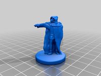
Dragonborn / Half-Dragon Summoner with Standard Base
...commons - attribution - non-commercial (cc by-nc 3.0) by poikilos and anno1066 based on dragonborn summoner by anno1066 jun...
thingiverse
free

Kuo-Toa Archpriest, High Priest or Cleric 28mm Miniature
...archpriest a.k.a. high priest. license cc by-nc-sa 3.0 by poikilos and jonlemurcreative commons - attribution - non-commercial - share-alike...
thingiverse
free

Dwarf Wizard with Ray of Frost
...specifically the hill dwarf or mountain dwarf height. authors poikilos and dutchmogul (based on morek brightstone, outcast dwarven sorcerer...
Jgaurora
thingiverse
free
accessorio JGAURORA by raffaelemobile
...accessorio jgaurora by raffaelemobile
thingiverse
stampato con jgaurora a3s riempimento 10% pareti 0.8
thingiverse
free
JGAurora Filament Guide by coogle
...jgaurora filament guide by coogle
thingiverse
a simple filament guide for the jgaurora printer
thingiverse
free
JGAURORA A5 z stabilizer
...jgaurora a5 z stabilizer
thingiverse
jgaurora a5 z stabilizer
roller size 22mm
thingiverse
free

LED Light for JGAurora A5
...led light for jgaurora a5
thingiverse
a light for jgaurora a5 made with led stripes and l-profile as a holder.
thingiverse
free

spring guid Jgaurora A5 by delichoc45
...spring guid jgaurora a5 by delichoc45
thingiverse
guide ressort jgaurora a5
thingiverse
free
JGAurora A5 side toolbox by P_Erhard
...jgaurora a5 side toolbox by p_erhard
thingiverse
toolboxes that clip into the side of the jgaurora a5 frame.
thingiverse
free
JGAURORA A5s Display Cover by nethunter27
...jgaurora a5s display cover by nethunter27
thingiverse
this is a jgaurora a5s displaycover.....from my printer,and my design!
thingiverse
free

Calibration Tool for JGAurora A1
...oon...
visit our jgaurora mkii upgrades group here at thingiverse:https://www.thingiverse.com/groups/jgaurora-mk2-upgrades/things
thingiverse
free
SKR mount for JGAURORA A5S
... hold the skr 1.3 control board to the posts in the jgaurora a5s chassis. holds a 40x10 fan for airflow across driver heatsinks.
thingiverse
free

m8 bowden connector for jgaurora a5 by death4u
...coupler for on the extruder of my jgaurora a5 broke. the original design had m6 and m10 couplers but the jgaurora a5 needed a m8.
A3S
3ddd
$1

AUDI A3 2007
...audi a3 2007
3ddd
audi , a3
audi a3 2007
3ddd
free

Botero A3
...botero a3
3ddd
botero , masiero
современный бра botero a3. моделил по фото.
design_connected
$13

A3 Stool
...a3 stool
designconnected
gubi a3 stool computer generated 3d model. designed by lorey, paul.
3ddd
$1

Slipper Bath A3
...slipper bath a3
3ddd
toto
slipper bath a3
turbosquid
$25

AUG A3
...uid
royalty free 3d model aug a3 for download as fbx and obj on turbosquid: 3d models for games, architecture, videos. (1563951)
3d_export
$39

Samsung Galaxy A3 and A3 Duos Black 3D Model
...ellphone smartphone cellular high detailed photoreal vray hdri
samsung galaxy a3 and a3 duos black 3d model nongon 93820 3dexport
3d_export
$39

Samsung Galaxy A3 and A3 Duos White 3D Model
...ellphone smartphone cellular high detailed photoreal vray hdri
samsung galaxy a3 and a3 duos white 3d model nongon 93861 3dexport
3d_export
$39

Samsung Galaxy A3 and A3 Duos Silver 3D Model
...llphone smartphone cellular high detailed photoreal vray hdri
samsung galaxy a3 and a3 duos silver 3d model nongon 94016 3dexport
turbosquid
$39

Asteroid-A3
... available on turbo squid, the world's leading provider of digital 3d models for visualization, films, television, and games.
turbosquid
$26

Audi A3
... available on turbo squid, the world's leading provider of digital 3d models for visualization, films, television, and games.
Reference
turbosquid
$1

horse reference
...id
royalty free 3d model horse reference for download as max on turbosquid: 3d models for games, architecture, videos. (1332096)
turbosquid
$1

Hyena reference
...id
royalty free 3d model hyena reference for download as max on turbosquid: 3d models for games, architecture, videos. (1180809)
turbosquid
$15

Body reference
...alty free 3d model body reference for download as fbx and obj on turbosquid: 3d models for games, architecture, videos. (1583572)
turbosquid
$20

Reference Monitor
... available on turbo squid, the world's leading provider of digital 3d models for visualization, films, television, and games.
3ddd
free
Аудио колонки - KEF - Reference
...аудио колонки - kef - reference
3ddd
kef , колонки
аудио колонки - kef - reference
turbosquid
$1

Lion reference
...ce
turbosquid
royalty free 3d model lion for download as max on turbosquid: 3d models for games, architecture, videos. (1180287)
turbosquid
$20

Female Reference+3D
... available on turbo squid, the world's leading provider of digital 3d models for visualization, films, television, and games.
turbosquid
$20

Klipsch Reference RS62
... available on turbo squid, the world's leading provider of digital 3d models for visualization, films, television, and games.
turbosquid
$20

Klipsch Reference RS52
... available on turbo squid, the world's leading provider of digital 3d models for visualization, films, television, and games.
turbosquid
$20

Klipsch Reference RS42
... available on turbo squid, the world's leading provider of digital 3d models for visualization, films, television, and games.