Thingiverse

j-head/e3d v6 mount with mini differential ir sensor for Flying Bear P905 by locnhinho
by Thingiverse
Last crawled date: 3 years ago
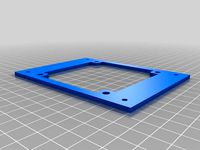
J-head/e3d v6 mount plate with mini differential IR sensor for Flying Bear P905
Update 9/13/2020: Update for the original sensor mount
Update 5/8/2018: Add Cura profile for eSUN ABS and a 3DBenchy print (blue)
Update 5/6/2018: Update Cura profile for eSUN PLA+ with an 3D Benchy print (pink)
Update 5/2/2018: Add Cura profile for eSUN PLA+
Update 3/29/2018: Add printer setting for PLA/ABS/PETG
Update 2/17/2018: Add a compact version of the mini ir sensor mount.
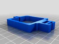
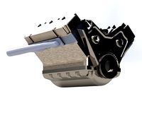
e3d v6/j-head mount:
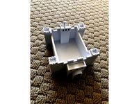
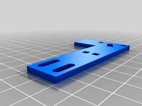
This is the mount plate for e3d/j-head v6 hotend. This is a re-mix of e3d v6 mount plate by TH3D. The STL model is modified to similar size as the u-shape mount - https://reprapchampion.com/products/aluminum-groove-mount-for-e3d-v6-hotend-for-delta-reprap-kossel-mini-3d-printer. This does works and I had printed a few models.
After I made this STL model, I had since moved to an all aluminium mount plate by modify the u-shape mount plate as following:
Drill two holes and threaded them accordingly. The hole offset should be 6.1mm from one of the other set of hole. You don't have to threaded them but will make installing the hotend much simple. (My brother-in-law did this for me since he works in CNC.)
Using the STL mount as model, cut the aluminium to fit the Flying Bear P905 extruder mount bracket. It is so tight in term of space. You can screw both the STL model and the aluminium u-shape plate together. Then hand hex saw off the portion with the opening.
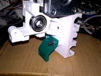
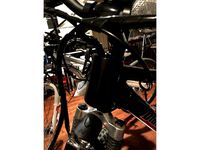
In order to mount this, you need to clip off a bit of the top fin. To do this, assemble the e3d/j-head hotend and position according. For the side that touch the mount bracket, use a cutting plier and clip off a bit.
To mount, first hand tight both screws and make sure it is flat. Then slowly tighten each side - just a little bit each side in rotation.
Included a test model print from https://www.thingiverse.com/thing:1363023.
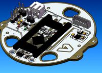
Mini IR differential sensor
This mini IR differential sensor is from https://miscsolutions.wordpress.com/mini-height-sensor-board. In order to get this to work with the Flying Bear P905 Marlin FW, you need to modify the firmware to default to digital output and output low on trigger. I had modified the firmware to always default to digital output. Then change the code to drive the LED PIN on trigger and the output pin to low on trigger. Due to this, the wire connection has changed. The file MiniIRSensorSmd.hex is the new firmware with the above changes.
To program the updated firmware, you will need to install those 6 PIN's on the IR sensor. Then use Arduino as an ISP to program the firmware. Many web page provides instruction on how to do this. For wiring, instead using the output in the original 3 PIN connector, use the PIN SCK pin.
* * *
Vcc MOSI GND
* * *
MISO SCK Reset
Use this SCK pin instead
This SCK pin will be 5V on non-trigger and 0V on triggered.
For the mount, you now have two options:
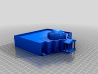
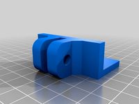
Option A: Use the modified DC42 Shield STL model accordingly. It is mounted along with the fan duct.
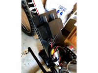
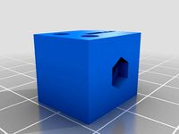
Option B: Use the ET-compact-mini-ir-sensor-mount.stl. This is a compact version that can be mount on the printer x-axis bracket. In order to do this, you need to solder wire directly on the mini ir sensor board instead using the pin header. The pin header is just too large. With direct soldered wire, it is much more compact. Print setting: 0.2 layer height, 50% infill, print on its side, and add zig-zag support at 5%.
With option B, you can now switch out the 30mm fan with a 40 mm fan. Using the noctua 40mm fan, it is dead quite and absolutely no vibration. In order to mount the 40 mm fan, you need to print yourself a 40mm fan mount from here - https://www.thingiverse.com/thing:929326. Please note that I have to scale the x dimension by 102% with PLA or print with PETG. Otherwise, it breaks with PLA. In addition, when mounting, it does push the fan duct against the x-axis bracket a bit. Just be aware of this. Some day or some one can design a 40 mm fan duct that offsets by 3.8mm.
Original Auto Bed Level Sensor
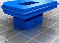
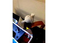
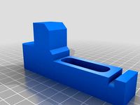
If you don't have the Mini IR differential sensor, you can use the original auto bed level sensor. Print the STL file "ET-AutoLevelSensorMount-53x42mm.stl" and various adjust plate "ET-AutoLevelSensorMount-53x42mm plate x.xx.stl". These plate allows you to adjust the z-offset height. Make sure that you print these plate at 0.2 initial layer height and 0.05 layer height.
Blower Fan
For blower fan, see this - https://www.thingiverse.com/thing:2843816.
All Metal Heat Break
If you want to print longer and higher temperature, consider swap out the heat break with this all metal high quality titanium alloy - https://www.aliexpress.com/item/high-quality-V6-titanium-alloy-heat-break-TC4-for-E3D-V6-HOTEND-heater-block-1-75MM/32853548000.html?spm=2114.search0103.0.0.522b3d57COcR9b. The 3D benchy printed in blue is with this heat break. Make sure you set the retraction to 3mm. Please note that this only works with ABS. With PLA, you will get jam. For PLA, use the heat break with PTFE. Have not tried PETG yet.
eSUN PLA Printer Setting (eSUN-PLA.curaprofile):
Extruder 190 degree C
Extruder 200 degree C first layer
Bed 60 degree C first layer only
Flow 95%
Initial layer flow 85%
Fan 75%
Speed 50mms/
Wall 25mm/s
Brim 8mm
eSUN ABS Printer Setting (eSUN-ABS.curaprofile):
Extruder 225/230 degree C layer 0
Bed 80 degree C
Flow 100%/88% layer 0
Fan 75%
Speed 40mm/s
Wall 20mm/s
Retract 3mm (for all metal heat break)
Brim 8mm
eSUN PETG Printer Setting:
Extruder 225 degree C
Bed 80 degree C first layer only
Flow 95%
Fan 75%
Speed 40mm/s
Wall 20mm/s
Brim 8mm
Layer height 0.25
Retraction 3mm
Travel 120mm/s
Combing mode off
Update 9/13/2020: Update for the original sensor mount
Update 5/8/2018: Add Cura profile for eSUN ABS and a 3DBenchy print (blue)
Update 5/6/2018: Update Cura profile for eSUN PLA+ with an 3D Benchy print (pink)
Update 5/2/2018: Add Cura profile for eSUN PLA+
Update 3/29/2018: Add printer setting for PLA/ABS/PETG
Update 2/17/2018: Add a compact version of the mini ir sensor mount.
e3d v6/j-head mount:
This is the mount plate for e3d/j-head v6 hotend. This is a re-mix of e3d v6 mount plate by TH3D. The STL model is modified to similar size as the u-shape mount - https://reprapchampion.com/products/aluminum-groove-mount-for-e3d-v6-hotend-for-delta-reprap-kossel-mini-3d-printer. This does works and I had printed a few models.
After I made this STL model, I had since moved to an all aluminium mount plate by modify the u-shape mount plate as following:
Drill two holes and threaded them accordingly. The hole offset should be 6.1mm from one of the other set of hole. You don't have to threaded them but will make installing the hotend much simple. (My brother-in-law did this for me since he works in CNC.)
Using the STL mount as model, cut the aluminium to fit the Flying Bear P905 extruder mount bracket. It is so tight in term of space. You can screw both the STL model and the aluminium u-shape plate together. Then hand hex saw off the portion with the opening.
In order to mount this, you need to clip off a bit of the top fin. To do this, assemble the e3d/j-head hotend and position according. For the side that touch the mount bracket, use a cutting plier and clip off a bit.
To mount, first hand tight both screws and make sure it is flat. Then slowly tighten each side - just a little bit each side in rotation.
Included a test model print from https://www.thingiverse.com/thing:1363023.
Mini IR differential sensor
This mini IR differential sensor is from https://miscsolutions.wordpress.com/mini-height-sensor-board. In order to get this to work with the Flying Bear P905 Marlin FW, you need to modify the firmware to default to digital output and output low on trigger. I had modified the firmware to always default to digital output. Then change the code to drive the LED PIN on trigger and the output pin to low on trigger. Due to this, the wire connection has changed. The file MiniIRSensorSmd.hex is the new firmware with the above changes.
To program the updated firmware, you will need to install those 6 PIN's on the IR sensor. Then use Arduino as an ISP to program the firmware. Many web page provides instruction on how to do this. For wiring, instead using the output in the original 3 PIN connector, use the PIN SCK pin.
* * *
Vcc MOSI GND
* * *
MISO SCK Reset
Use this SCK pin instead
This SCK pin will be 5V on non-trigger and 0V on triggered.
For the mount, you now have two options:
Option A: Use the modified DC42 Shield STL model accordingly. It is mounted along with the fan duct.
Option B: Use the ET-compact-mini-ir-sensor-mount.stl. This is a compact version that can be mount on the printer x-axis bracket. In order to do this, you need to solder wire directly on the mini ir sensor board instead using the pin header. The pin header is just too large. With direct soldered wire, it is much more compact. Print setting: 0.2 layer height, 50% infill, print on its side, and add zig-zag support at 5%.
With option B, you can now switch out the 30mm fan with a 40 mm fan. Using the noctua 40mm fan, it is dead quite and absolutely no vibration. In order to mount the 40 mm fan, you need to print yourself a 40mm fan mount from here - https://www.thingiverse.com/thing:929326. Please note that I have to scale the x dimension by 102% with PLA or print with PETG. Otherwise, it breaks with PLA. In addition, when mounting, it does push the fan duct against the x-axis bracket a bit. Just be aware of this. Some day or some one can design a 40 mm fan duct that offsets by 3.8mm.
Original Auto Bed Level Sensor
If you don't have the Mini IR differential sensor, you can use the original auto bed level sensor. Print the STL file "ET-AutoLevelSensorMount-53x42mm.stl" and various adjust plate "ET-AutoLevelSensorMount-53x42mm plate x.xx.stl". These plate allows you to adjust the z-offset height. Make sure that you print these plate at 0.2 initial layer height and 0.05 layer height.
Blower Fan
For blower fan, see this - https://www.thingiverse.com/thing:2843816.
All Metal Heat Break
If you want to print longer and higher temperature, consider swap out the heat break with this all metal high quality titanium alloy - https://www.aliexpress.com/item/high-quality-V6-titanium-alloy-heat-break-TC4-for-E3D-V6-HOTEND-heater-block-1-75MM/32853548000.html?spm=2114.search0103.0.0.522b3d57COcR9b. The 3D benchy printed in blue is with this heat break. Make sure you set the retraction to 3mm. Please note that this only works with ABS. With PLA, you will get jam. For PLA, use the heat break with PTFE. Have not tried PETG yet.
eSUN PLA Printer Setting (eSUN-PLA.curaprofile):
Extruder 190 degree C
Extruder 200 degree C first layer
Bed 60 degree C first layer only
Flow 95%
Initial layer flow 85%
Fan 75%
Speed 50mms/
Wall 25mm/s
Brim 8mm
eSUN ABS Printer Setting (eSUN-ABS.curaprofile):
Extruder 225/230 degree C layer 0
Bed 80 degree C
Flow 100%/88% layer 0
Fan 75%
Speed 40mm/s
Wall 20mm/s
Retract 3mm (for all metal heat break)
Brim 8mm
eSUN PETG Printer Setting:
Extruder 225 degree C
Bed 80 degree C first layer only
Flow 95%
Fan 75%
Speed 40mm/s
Wall 20mm/s
Brim 8mm
Layer height 0.25
Retraction 3mm
Travel 120mm/s
Combing mode off
Similar models
thingiverse
free

Mini differential IR / E3D V6 stock fan mount by maczero
... / e3d v6 stock fan mount by maczero
thingiverse
a mount for dc42s mini ir probe (ver1.1) that fits on the stock 30mm e3d v6 fan
thingiverse
free

IR Probe Mount for E3D V6 Shroud by rs4race
...
ir probehttps://miscsolutions.wordpress.com/mini-height-sensor-board/
e3d v6http://e3d-online.com/e3d-v6/full-kit/v6-3mm-direct
thingiverse
free

30mm V6 Fan Holder for Flying Bear P905 by mrnachoman
...e soon that allows you to convert the standard flying bear p905 hotend over to the e3d v6. let me know if you have any questions.
thingiverse
free

E3D V6 Adapter and DC42 Differential IR sensor mount by PDBeal
...igned in onshape:https://cad.onshape.com/documents/df1930401d5350ef2521663b/w/2a8fb45251b1811ec75f5d03/e/bddac8db7c320469b9c43db7
thingiverse
free

E3D Mount with fan and autolevel for gantry plate
...extruder mount for an e3d v6 hotend that fits an open builds v-slot 20mm gantry plate with support for fan and auto level sensor.
thingiverse
free

Proximity Sensor Mount (12mm diam) for E3D v6 integrated fan support by elkayem
...to be mounted directly to an e3d v6 (or similar heat break. i based the sensor mount on the...
thingiverse
free
Mini Height Differential IR Sensor Board Mount for E3D v6 / Prusa i3 Rework by GiulianoM
...t onto the bottom two m4 bolts for the "e3d v6 compact extruder for i3 rework":
http://www.thingiverse.com/thing:725082
thingiverse
free

e3d v6 30mm layer fan by Rico_3D
...cooling fan for the e3d v6 hotend.
designed to fit the monoprice mini but could be used on any printer with the same style mount.
thingiverse
free

E3D v6 mount for Kossel XL with Mini ir sensor and 40mm coolingfans by 3DHEIJ
... for kossel xl with mini ir sensor and 40mm coolingfans by 3dheij
thingiverse
all in one mount for kossel xl and mini ir sensor.
thingiverse
free

D-Bot differential IR Z-probe bracket by ThePhilStrongProject
...verse
a bracket to mount this:
https://miscsolutions.wordpress.com/mini-height-sensor-board/
bolts in front of the e3d v6 clamp.
Locnhinho
thingiverse
free
Monticello by locnhinho
...the hall
increase the wall to 1.2mm
shift the dome to not touch the wall due to wall increase to 1.2mm
pull out the windows a bit
thingiverse
free
Castle by locnhinho
... top surface, extrude down to base
fix and enlarge the flag
inscribe "castle by alyssa ho 4th grade 2021" at the bottom
thingiverse
free

Protector for Polaris D30 UWF Quick Disconnect by locnhinho
...designed this to protect it from getting broken. if you want to buy one, look at this link https://www.ebay.com/itm/193622399518.
thingiverse
free
XT60 Replacement for DC2.1mm Hailong Case by locnhinho
...ject some hot glue into the two small holes
for the xt60 cover, get it from this one - https://www.thingiverse.com/thing:4793612.
thingiverse
free
Bafang Wire Housing for Bike Hand Bar by locnhinho
... look nice:
sand it with 240, 120, and 400
spray paint
included the fusion 360 file so that you can modify it for your fork size.
thingiverse
free

Polaris Wheel Nut by locnhinho
...replacement. see polaris 280 small wheel holder.stl and image attached. you will need an m5 hex nut as well as a longer m5 screw.
thingiverse
free
Ego Battery Adapter to XT60 by locnhinho
...solder. heat up the plate first add a blob of solder. then joint with the wire.
on the other end, solder to xt60 female connector
thingiverse
free
Raspberry PI Zero Camera Mount for Flying Bear P905 by locnhinho
... 50mm fan blower, it now touched the 50mm fan blower. as such, added second version to move the camera out by 0.5" or 13 mm.
thingiverse
free

Hailong Battery Mounting Plate by locnhinho
... repeat for the other two holes if required.
please note that there are two versions - one for 50mm frame and one for 40mm frame.
thingiverse
free

Dual mosfet for Flying Bear P905 by locnhinho
...rilla mosfet
you can use 3mm screw with nut to mount the bracket to the mosfet mounting plate. or use those computer disk screw.
P905
thingiverse
free

Turbo fan P905 by maanuuu
...turbo fan p905 by maanuuu
thingiverse
cooling system for flyingbear p905
for turbo fan 12v 5015s
thingiverse
free
Z Limit for Flyingbear p905 by groundhogday
...z limit for flyingbear p905 by groundhogday
thingiverse
z limit for flyingbear p905
thingiverse
free
Cable Holder for Flyingbear p905 by groundhogday
...cable holder for flyingbear p905 by groundhogday
thingiverse
cable holder for flyingbear p905
thingiverse
free

Filament cleaner for Flyingbear p905 by groundhogday
...filament cleaner for flyingbear p905 by groundhogday
thingiverse
filament cleaner for flyingbear p905
thingiverse
free
Belt Clip for Flyingbear p905 by groundhogday
...belt clip for flyingbear p905 by groundhogday
thingiverse
belt clip for flyingbear p905
thingiverse
free
Spool holder for Flyingbear p905 by groundhogday
...spool holder for flyingbear p905 by groundhogday
thingiverse
spool holder for flyingbear p905
thingiverse
free

P905 Feet by jbrasel
... your p905 3d printer. hot glue a small amount of fabric to the bottom of the feet to stop your desktop for getting scratched up.
thingiverse
free
Dial indicator holder for Flyingbear p905 by groundhogday
...dial indicator holder for flyingbear p905 by groundhogday
thingiverse
dial indicator holder for flyingbear p905
thingiverse
free

FlyingBear P905 flex tube holder by lugamodder
...flyingbear p905 flex tube holder by lugamodder
thingiverse
flex tube holder for flyingbear p905
thingiverse
free
Cover for fan 80x80x10 for Flyingbear p905 by groundhogday
...cover for fan 80x80x10 for flyingbear p905 by groundhogday
thingiverse
cover for fan 80x80x10 for flyingbear p905
Differential
turbosquid
$10

differential
...uid
royalty free 3d model differential for download as sldas on turbosquid: 3d models for games, architecture, videos. (1256050)
3d_ocean
$3
Differential
...ender in both formats(blend and obj). it is perfect for showing the inner parts and principles of a differential. check out my...
3d_ocean
$15

Differential interaxial
...l differential from 4×4 autovehicles made in autocad. the file is an assembly which contains multiple parts of this differential.
3d_export
$30
differential gearbox
...differential gearbox
3dexport
3d model of a differential gearbox.<br>modeled in solidworks.<br>rendered in keyshot.
turbosquid
$29

Automobile Differential
... free 3d model automobile differential 3d for download as iam on turbosquid: 3d models for games, architecture, videos. (1296581)
turbosquid
$29
Differential mode
...oyalty free 3d model differential 3d mode for download as iam on turbosquid: 3d models for games, architecture, videos. (1293829)
3d_export
$15

Differential 3D Model
...rear drive car auto part axle planetary gear animation 3d cog wheel tyre engine
differential 3d model dragosburian 80662 3dexport
3d_export
$8
differential gear assembly
...l gear assembly
3dexport
you will get both .stl and .sldprt format of differential gear assembly form here with reasonable cost.
3d_export
$20
Animated differential 3D Model
...ar drive car auto part axle planetary gear animation 3d cog wheel tyre
animated differential 3d model dragosburian 80258 3dexport
turbosquid
$27

Torsen LSD helica Differential
...e 3d model torsen lsd helica differential for download as iam on turbosquid: 3d models for games, architecture, videos. (1290429)
Ir
turbosquid
$65
FLIR Vue Pro IR Camera
... available on turbo squid, the world's leading provider of digital 3d models for visualization, films, television, and games.
turbosquid
$10
Subwoofer F&D IHOO 5.1 IR
...oofer f&d ihoo 5.1 ir for download as sldpr, max, and ige on turbosquid: 3d models for games, architecture, videos. (1523229)
3ddd
$1

Grohe Eurosmart CE IR electronic
...t ce ir electronic
3ddd
grohe , смеситель
смеситель для раковины с инфракрасным сенсором
turbosquid
$40
AK 47 Dual Laser Sight with IR Illuminator
...k 47 dual laser sight with ir illuminator for download as obj on turbosquid: 3d models for games, architecture, videos. (1586129)
turbosquid
$30
IR Bracelet Light Therapy Pain Recovery System
...acelet light therapy pain recovery system for download as ige on turbosquid: 3d models for games, architecture, videos. (1493109)
3ddd
$1
GRAMERCY HOME - Bastian Chandelier CH058-5-IR
...5-ir
3ddd
gramercy home
gramercy home
bastian chandelier
ch058-5-ir
ширина 47 см
глубина 47 см
высота 25 см
www.gramercy-home.ru
turbosquid
$20
IR-RF PLC USB TRANSMITTER 2014 RAW
... available on turbo squid, the world's leading provider of digital 3d models for visualization, films, television, and games.
turbosquid
$2
Speakers Centr F-D - Sven IHOO 5-1 IR
... available on turbo squid, the world's leading provider of digital 3d models for visualization, films, television, and games.
turbosquid
$2
Speakers Front F-D F and D - Sven IHOO 5-1 IR
...) - sven ihoo 5-1 ir for download as max, ige, stl, and sldpr on turbosquid: 3d models for games, architecture, videos. (1144599)
3d_export
$15
be meyers mawl-c1 ir-laser
...station for more<br>tri count: 8,335 vertex count: 4,405 texture: pbr-4k<br>https://www.artstation.com/artwork/yaed4v
E3D
cg_studio
free

e3d model
...e3d model
cgstudio
- e 3d model, royalty free license available, instant download after purchase.
turbosquid
$2
Syringe C4D (E3D Ready)
...lty free 3d model syringe c4d (e3d ready) for download as c4d on turbosquid: 3d models for games, architecture, videos. (1336720)
turbosquid
$12
Microphone USB E3D and C4D
...ree 3d model microphone usb e3d & c4d for download as c4d on turbosquid: 3d models for games, architecture, videos. (1568216)
cg_studio
$35
Picture Frame Style E3d model
...
cgstudio
.3ds .max .obj .wrl - picture frame style e 3d model, royalty free license available, instant download after purchase.
cg_studio
$10

EVE from cartoon WALL-E3d model
...3d model
cgstudio
.3ds .max - eve from cartoon wall-e 3d model, royalty free license available, instant download after purchase.
cg_studio
$45
WW2 Pz VI Tiger SdKfz 181 Ausf. E3d model
....lwo .ma .max .obj - ww2 pz vi tiger sdkfz 181 ausf. e 3d model, royalty free license available, instant download after purchase.
3d_ocean
$6

Love Heart Element 3D & Cinema4D
...red heart romance valentines simple project simple heart models e3d files, cinema 4d files & obj files step 1...
3d_export
$14

Xiaomi mi band 6
...360. materials for rendering are configured in keyshot, v-ray, e3d blender. the keyshot has 6 strap colors configured. there...
3d_export
$20

apple airpods 3
...max vray, keyshot, e3d. - formats: 3dm, aep, bip, e3d f3d, iges, ksp, max 2013, max 2016, obj, fbx,...
3d_export
$20
Samsung galaxy tab s8 ultra
...blue, beige, white, black, graphite. - in blender and e3d one color of the model is configured, graphite. -...
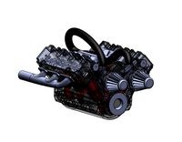
V6
3d_export
$100
v6 engine
...engine
3dexport
complete v6 engine modeled on solidworks 2017 along with .stl, .sldprt and .sldasm of all th parts and assembly.
3d_export
$10
V6 engine
... the first v6 engines were designed and produced independently by marmon motor car company, deutz gasmotoren fabrik and delahaye.
3d_export
$35
v6 engine
...s a complete model of a v6 engine containing over 400 components. you can contact me for a video of all the components assembling
3d_export
$10

v6 engine
...v6 engine
3dexport
turbosquid
$25

Bed1001-v6
... available on turbo squid, the world's leading provider of digital 3d models for visualization, films, television, and games.
turbosquid
$22
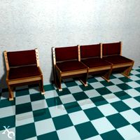
Chair2-v6
... available on turbo squid, the world's leading provider of digital 3d models for visualization, films, television, and games.
turbosquid
$20

V6.mb
... available on turbo squid, the world's leading provider of digital 3d models for visualization, films, television, and games.
3d_export
$20
V6 engine
...rovided in this package is all the parts in sldprt format and assembly in sldasm format. i can also convert the format on demand.
3ddd
$1
Стол V6
...6" в стиле дизельпанк изготовлен из блока двигателя, 4х поршней и 4х шатунов.
столешница изготовлена из стекла толщиной 8мм.
cg_studio
$199
V6 VVTi3d model
...v6 vvti3d model
cgstudio
.3ds - v6 vvti 3d model, royalty free license available, instant download after purchase.
J
3d_export
$17

J-7mg
...j-7mg
3dexport
j-7mg
3d_export
$5

j hook
...j hook
3dexport
j hook
3d_export
$17

J-21 jastreb
...j-21 jastreb
3dexport
j-21 jastreb
3d_export
$17

Chengdu J-10
...chengdu j-10
3dexport
chengdu j-10
turbosquid
$30

J-7
...j-7
turbosquid
royalty free 3d model j-7 for download as max on turbosquid: 3d models for games, architecture, videos. (1538420)
turbosquid
$14

Fence J
...turbosquid
royalty free 3d model fence j for download as fbx on turbosquid: 3d models for games, architecture, videos. (1313345)
turbosquid
$7

J for Jug
...rbosquid
royalty free 3d model j for jug for download as max on turbosquid: 3d models for games, architecture, videos. (1688347)
turbosquid
$5

Letter J
...urbosquid
royalty free 3d model letter j for download as max on turbosquid: 3d models for games, architecture, videos. (1408483)
turbosquid
$5

Letter j
...urbosquid
royalty free 3d model letter j for download as max on turbosquid: 3d models for games, architecture, videos. (1408481)
turbosquid
$2

FONT J
...quid
royalty free 3d model font j for download as ma and obj on turbosquid: 3d models for games, architecture, videos. (1548493)
Sensor
3d_export
free

parking sensor
...parking sensor
3dexport
car parking sensor
turbosquid
$1
Sensor
... available on turbo squid, the world's leading provider of digital 3d models for visualization, films, television, and games.
3d_export
$5
Smoke sensor
...port
smoke sensor, can be an impressive element for your projects. easy to use, realistic image, low polygon, quality materials.
3d_export
$5
Air Quality Sensor v1
...air quality sensor v1
3dexport
air quality sensor v1
3d_export
$15
float sensor
...e up render. - all parts and materials are logically named. other formats ================= - collada (.dae) - autodesk fbx - obj
turbosquid
$26
Wind sensor C
...free 3d model wind sensor c for download as 3ds, obj, and fbx on turbosquid: 3d models for games, architecture, videos. (1328943)
turbosquid
$26
Wind sensor B
...free 3d model wind sensor b for download as 3ds, obj, and fbx on turbosquid: 3d models for games, architecture, videos. (1328168)
3d_export
$5
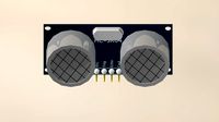
ultrasound sensor
...ivers convert ultrasound into electrical signals, and transceivers can both transmit and receive ultrasound. export in: -obj -fbx
3ddd
free
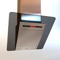
Вытяжка Shindo pallada sensor
... вытяжка
вытяжка shindo pallada sensor. в двух размерах - 600 и 900. текстуры в комплекте.
turbosquid
$52
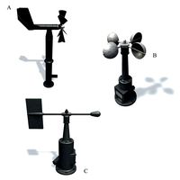
Wind sensor A B C
...
royalty free 3d model wind sensor a b c for download as fbx on turbosquid: 3d models for games, architecture, videos. (1408406)
Flying
design_connected
$13
Fly-Fly
...fly-fly
designconnected
foscarini fly-fly computer generated 3d model. designed by palomba, ludovica.
3ddd
$1

Foscarini FLY-FLY
...foscarini fly-fly
3ddd
foscarini , fly-fly
foscarini fly-fly
полигонов: 73 022
3ddd
$1

Foscarini Fly-Fly
...foscarini fly-fly
3ddd
foscarini
люстра fly-fly
3d_export
free
fly
...fly
3dexport
fly
turbosquid
$15

fly fishing fly
... available on turbo squid, the world's leading provider of digital 3d models for visualization, films, television, and games.
design_connected
free

Fly
...fly
designconnected
free 3d model of fly by alias designed by acerbis, marco.
design_connected
$13

Fly
...fly
designconnected
kartell fly computer generated 3d model. designed by laviani, ferruccio.
design_connected
$13
Fly
...fly
designconnected
zanotta fly computer generated 3d model. designed by robson , mark .
3d_ocean
$10
3D Fly
...3d fly
3docean
3d fly 3ds max fly
this is a 3d fly model.
3ddd
free
Fly mood
...fly mood
3ddd
fly mood , душ
душевая панель fly mood
Bear
3d_export
$6
Bear
...bear
3dexport
bear
3d_export
$5
bearing
...bearing
3dexport
bearing
3d_export
$12
bear
...bear
3dexport
bear for 3d printing toy
3d_ocean
$9
Bearing
...ne ball ballbea bearing bearings engine hard industrial machine mechanic metal part piece plastic ring screw sphere steel
bearing
archibase_planet
free

Bear
...bear
archibase planet
statuette bear picturesque element
bear - 3d model (*.gsm+*.3ds) for interior 3d visualization.
3d_export
$5

bear
...bear
3dexport
bear have a stl.,3dm files
archibase_planet
free

Bear
...bear
archibase planet
bear animals omnivorous animal
bear angry n250907- 3d model (*.gsm+*.3ds) for interior 3d visualization.
archibase_planet
free

Bear
...bear
archibase planet
bear animals omnivorous animal
bear easy n250907 - 3d model (*.gsm+*.3ds) for interior 3d visualization.
3ddd
$1

Teddy bear
...teddy bear
3ddd
teddy bear , медведь
teddy bear :)
3d_ocean
$12
Bear
... formats. created with 3d max 9.0. this file is very useful for learning & rigging. it can be used for any professional work.
Mini
turbosquid
$10
Mini Mini Luceplan
...
royalty free 3d model mini mini luceplan for download as max on turbosquid: 3d models for games, architecture, videos. (1227359)
3d_ocean
$39
Mini Cooper
...mini cooper
3docean
cabrioler cooper mini
mini cooper cabrioler
3d_export
$30

Mini lathe
...mini lathe
3dexport
mini lathe
3d_export
$5
mini mouse
...mini mouse
3dexport
mini mouse
3d_export
$5
mini house
...mini house
3dexport
mini house
3d_export
free

Mini Mecha
...mini mecha
3dexport
concept of mini mecha
3d_ocean
$20
Mini Gun
...mini gun
3docean
gatling gun gun machine gun mini gun weapon
model of a mini gatling gun.
3ddd
free
Herve mini
... кофейный , herve
http://www.mobiliavenanti.it/ru/products/hervè-mini
3d_export
$5
mini wall
...mini wall
3dexport
mini wall for living room
3d_export
$5

mini bank
...mini bank
3dexport
mini bank 3d model
Head
3d_export
$5

head
...head
3dexport
simulated female head.
3d_ocean
$5

Deer Head
...deer head
3docean
deer head
simple model of deer head with neck.
cg_studio
$25

Marble Head - Head A3d model
... - head a3d model
cgstudio
.ma - marble head - head a 3d model, royalty free license available, instant download after purchase.
turbosquid
$5
Head
...ad
turbosquid
royalty free 3d model head for download as max on turbosquid: 3d models for games, architecture, videos. (1230068)
turbosquid
free

The Head
...urbosquid
royalty free 3d model the head for download as max on turbosquid: 3d models for games, architecture, videos. (1386205)
turbosquid
free

Head
...
turbosquid
royalty free 3d model head for download as blend on turbosquid: 3d models for games, architecture, videos. (1276899)
3d_export
$10

bull head
...bull head
3dexport
bull head
3d_export
$5
girl head
...girl head
3dexport
head girl
3d_export
$5
Tigger-head
...tigger-head
3dexport
tigger-head
3d_export
$5

head on a spear
...head on a spear
3dexport
head on a spear
Mount
3d_export
free

mounting bracket
...mounting plate is the portion of a hinge that attaches to the wood. mounting plates can be used indoors, cabinetry and furniture.
turbosquid
$2

MOUNTING
... available on turbo squid, the world's leading provider of digital 3d models for visualization, films, television, and games.
turbosquid
free

Mounts
... available on turbo squid, the world's leading provider of digital 3d models for visualization, films, television, and games.
turbosquid
free

Mount Fuji
...fuji
turbosquid
free 3d model mount fuji for download as obj on turbosquid: 3d models for games, architecture, videos. (1579977)
3d_export
$5

Headphone mount LR
...headphone mount lr
3dexport
headphone mount l+r
turbosquid
$39

Mount rainier
...quid
royalty free 3d model mount rainier for download as fbx on turbosquid: 3d models for games, architecture, videos. (1492586)
turbosquid
$5

pipe mounting
...quid
royalty free 3d model pipe mounting for download as obj on turbosquid: 3d models for games, architecture, videos. (1293744)
turbosquid
$3

Mounting Tires
...uid
royalty free 3d model mounting tires for download as fbx on turbosquid: 3d models for games, architecture, videos. (1708511)
3d_export
$5

Magnetic GoPro Mount
...pro mount
3dexport
cool magnetic mount for gopro. allows you to mount the camera on flat metal surfaces and get exclusive shots.
turbosquid
$5

Stone Mount
...ty free 3d model stone mount for download as ma, obj, and fbx on turbosquid: 3d models for games, architecture, videos. (1370306)