Thingiverse
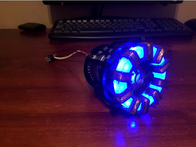
Iron man arc reactor by TheMaker77
by Thingiverse
Last crawled date: 3 years ago
The initial design came from a file that I found on Thingiverse; however, I am unable to locate the thing in order to give proper recognition. I am posting my make as I would like others to also have the opportunity to create this amazing prop.
If anyone is able to tell me from whom the design is feel free to let me know and the proper recognition will be given.
The files provided caused some problems due to their sizing, however after some experimentation on my part I have determined the scales at which the parts should be printed in order to assemble correctly. The following parts should be scaled by the following factors (I have also indicated the colours in which the parts could be printed):
bp1 (Transparent): x: 104% y: 104% z: 98.11%
bp2 (Silver): x: 103% y: 103% z: 100%
bp3 (Grey): x: 101% y: 101% z: 100%
bp4 (Silver): x: 100% y: 100% z: 100%
bp9 (Silver): x: 98% y: 98% z: 98%
dp1 (Grey): x: 109% y: 106% z: 100%
dp2 (Grey): x: 100% y: 100% z: 100%
dp3 (Grey): x: 100% y: 100% z: 100%
dp4 (Black): x: 100% y: 100% z: 100%
jp1 (Black): x: 100% y: 100% z: 100%
jp2 (Black): x: 100% y: 100% z: 100%
jp3 (Black): x: 104% y: 104% z: 100%
Bottom Detail (Silver): x: 100,5% y: 100,5% z: 100%
Combining Ring (Black): x: 100% y: 100% z: 100%
UPDATE: 17 March 2018
Thanks to DocHaynes it has come under my attention that it is not clear on how to assemble the Arc Reactor. In an effort to resolve this I have added some more photos which show some aspects of the model more clearly as well as a diagram showing how to parts fit onto one another and the quantity of parts required. furthermore the following instructions can be followed:
Print all the respective parts (Please note that I had to scale some of the parts to work correctly, the scales are indicated above).
Part bp9 has 10 holes on its base through which cap screws (M3 x 12) are placed in order to secure the parts jp1 (x5) and jp2 (x5). Enlarge the holes using a drill with a 2,5mm drill bit if required.
Fit part bp9 into the base of bp4.
x5 jp1 and x5 jp2 parts are required. At the base of these parts use a hand drill to drill a 2,5mm hole through which the cap screws will fit such that they can be fastened to the base of part bp9. (the parts should be fastened in an alternating fashion [jp1, jp2, jp1, jp2, etc])
Place part bp3 on top of bp4, once again it should be a snug fit.
place part bp2 onto part bp3 (snug fit required, if not snug enough some glue may be used to stick parts together, I recommend Cyanoacrylate).
Cut out a piece of wire mesh roughly 22mm in diameter and stick it in the centre top of part bp2.
Place part dp2 into the top sunk in surface of part bp2 (some sanding of part dp2 may be required for the part to fit).
Glue part dp4 to the top of part dp2.
In part dp3 drill a 3mm hole into the ends of two of the three arms, and in the third drill two 1mm holes. (This is for the cap screws to be able to mount the part to those below it and to add film detail to the model). Place the part on top of part dp4 and fasten or glue (it may also be required to drill holes into part dp4 in order to fasten part dp3 to it).
Place the combining ring on the inside of the 5 tall parts named jp2 and place the 5 jp2 parts into the respective slots of the ring (This ring can be seen in the pictures as the top ring).
Place the clear ring (dimensions shown on the diagram for manufacturing if printing clear PLA does not suffice) on top of part bp 2. (When adding LED's I added 10 to the bottom of the clear ring by drilling 10 holes at equally spaced intervals, the printed model bp1 has space for 10 5mm globe type LED's).
Take the 10 dp1 parts and wind some copper wire around them in order to gain the appearance of armature. After this place the 10 parts over the clear ring at equally spaced intervals. Ensure that the LED falls between two consecutive dp1 parts and not below them, else the light will not shine through as effectively.
Place part jp3 over the outside of the 5 jp1 and 5 jp2 parts (This ring can be seen as the bottom ring in pictures).
This concludes the build. Post process can be done according to your liking. I trust that this information will be useful to those wanting to build this model. Please feel free to leave me a comment if any further clarification is required.
Update: 13 May 2019
I have added parts, namely:
CR2032 Holder - this is a holder into which a CR2032 coin battery can be housed for the wiring of the electronics.
Arc Reactor Plug (print at 100% scale, at >80% infill (Black))- I realised that I was missing the plug piece that goes on the end of the cable running from the bottom of the Arc Reactor. In order to obtain the plug look I used six 2mm diameter metal pins, roughly 10mm in length, heated them up on one side and pushed them into the larger diameter side of the plug. the plastic should melt and during cooling will hold the metal pins in place. On the smaller diameter side of the plug I bent a 5mm wide 10mm long piece of metal plate into a "U" shape, heated up the legs of the "U" and pushed this into the plug. this serves to be able to connect the plug to the end of the wire.
Centre LED Holder (Print at 100% scale, >60% infill (Clear) - I realised that I was missing a piece which should be inserted into the centre of the Arc Reactor. this piece is required to be able to add the eleventh centre LED.
for the electronics I wired the eleven LED's in parallel (this means that I am able to run the LED's off of a low voltage and the current is split between the LED's (this means less bright LED's, but with the low voltage means a smaller battery can be used)). A CR2032 (3V, 250mAH or more) battery is then wired in series with a sliding micro switch and the loop completed back to the LED's. The white cable running from the bottom of the Arc Reactor is a 180mm long piece of 4 core electrical cable (the cable diameter is slightly smaller than that of the centre hole at the bottom of the Arc Reactor to allow for the positive and negative wires running from the battery to the switch, and from the switch to the LED's to fit snugly through the hole together.).
Similar models
3dbaza
$4

Delavega modular sofa DP1, DP2, DP4 (145540)
...15 + fbx<br>unit: millimeter<br>unwrapped uvs: yes<br>textures: yes<br>materials: yes<br>xform: yes
thingiverse
free

Printable LED Arc Reactor by Rocket828
...ses 14 leds and requires no other parts besides wires. it should fit on a maker bot if i'm right, it's 100mm in diameter.
cg_trader
$7

Modular sofa Delavega DP section DP1 DP2
...modular sofa delavega dp section dp1 dp2
cg trader
modular sofa delavega dp section dp1, dp2
2400mm x 1350mm x 750mm
cg_trader
$15

Delavega modular sofa dp1 dp3
...delavega modular sofa dp1 dp3
cg trader
model: delavega modular sofa dp1 dp3
cg_trader
$15

Delavega modular sofa dp1 d2 dp4
...delavega modular sofa dp1 d2 dp4
cg trader
model: delavega modular sofa dp1 d2 dp4
cg_trader
$15
Delavega modular sofa dp1 d2 dp3
...delavega modular sofa dp1 d2 dp3
cg trader
model: delavega modular sofa dp1 d2 dp3
thingiverse
free

Iron Man arc reactor with hidden wires and print in place stand by adrianmelia
...lue
-thin wire wrap wire
-19 super bright white leds
-li-poly battery
-li-poly usb charger
-jst switch
-short usb extension cable
thingiverse
free

IronMan (IronHeart) Riri Williams inspired ARC reactor by DaveMakesIt89
...thingiverse i drew up an arc reactor kind of similar to the style of riri williams diamond shape light...
thingiverse
free

Flat Arc Reactor for Cosplay by rjelbert
...is also in github here:https://github.com/rjelbert/arc-reactor
the holes are for fitting leds and the channels are for the wires.
grabcad
free

Iron Man ARC reactor v1.0
...iron man arc reactor v1.0
grabcad
its not the orginal but likewise
there are holes for leds in the outer ring.
Themaker77
thingiverse
free

Astronaut Hex Tiles by TheMaker77
...icolour printing techniques and to create a piece of art that can proudly be displayed.
test it out for yourself and be creative.
thingiverse
free

Satellite by TheMaker77
...les for the sections of the satellite that were not initially printed. the whole model can now be entirely printed and assembled,
thingiverse
free

Retro Rocket by TheMaker77
...order to build the rocket the following parts will be required:
1x body
3x booster
1x main thruster
3x booster thruster
1x window
Reactor
3d_export
$5

Arc reactor
...arc reactor
3dexport
arc reactor
turbosquid
$15

Reactor
...yalty free 3d model reactor for download as obj, c4d, and fbx on turbosquid: 3d models for games, architecture, videos. (1480694)
3d_export
$5

arc reactor
...arc reactor
3dexport
arc reactor model-no texture!
turbosquid
$8
Reactor
... available on turbo squid, the world's leading provider of digital 3d models for visualization, films, television, and games.
3d_ocean
$2

Arc Reactor
...hest iron ironman jace knockout man marvel model piece productions reactor stark tony
concept design for tony stark’s arc reactor
turbosquid
$99

Nuclear Reactor
... available on turbo squid, the world's leading provider of digital 3d models for visualization, films, television, and games.
turbosquid
$5
Nuclear reactor
... available on turbo squid, the world's leading provider of digital 3d models for visualization, films, television, and games.
turbosquid
$3

Reactor Small
... available on turbo squid, the world's leading provider of digital 3d models for visualization, films, television, and games.
turbosquid
free

reactor cloth.max
... available on turbo squid, the world's leading provider of digital 3d models for visualization, films, television, and games.
3d_ocean
$19
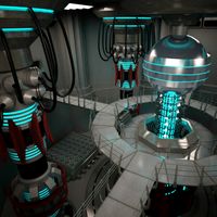
Scifi Base Reactor
...r plant power radiation reactor reator sci sci-fi structure subway
3d model scifi base reactor by alexrazum v-ray materials only.
Arc
archibase_planet
free
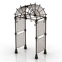
Arc
...arc
archibase planet
arc arch
arc - 3d model (*.gsm+*.3ds) for exterior 3d visualization.
archibase_planet
free

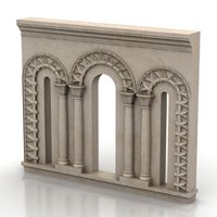
Arc
...arc
archibase planet
arc arch
arc n190113 - 3d model (*.gsm+*.3ds) for interior 3d visualization.
archibase_planet
free

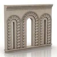
Arc
...arc
archibase planet
arc arch
arc 1 - 3d model (*.gsm+*.3ds) for interior 3d visualization.
archibase_planet
free
Arc
...arc
archibase planet
arc arch
arc 2 - 3d model (*.gsm+*.3ds) for interior 3d visualization.
archibase_planet
free
Arc
...arc
archibase planet
arc arch
arc 3 - 3d model (*.gsm+*.3ds) for interior 3d visualization.
archibase_planet
free
Arc
...arc
archibase planet
arc arch
arc n170413 - 3d model (*.gsm+*.3ds) for interior 3d visualization.
archibase_planet
free

Arc
...arc
archibase planet
arc arch
arc n130513 - 3d model (*.gsm+*.3ds) for interior 3d visualization.
archibase_planet
free

Arc
...arc
archibase planet
arc arch
arc n030813 - 3d model (*.gsm+*.3ds+*.max) for 3d visualization.
archibase_planet
free
Arc
...arc
archibase planet
arc arch
arc n290713 - 3d model (*.gsm+*.3ds) for interior 3d visualization.
archibase_planet
free

Arc
...arc
archibase planet
arc arch window
arc 1 - 3d model (*.gsm+*.3ds) for interior 3d visualization.
Iron
archibase_planet
free

Iron
...ase planet
iron flatiron flat iron smoothing-iron
iron scarlett sc1133s n260112 - 3d model (*.3ds) for interior 3d visualization.
archibase_planet
free

Iron
...et
iron flatiron flat iron smoothing-iron
iron black & decker n131213 - 3d model (*.gsm+*.3ds) for interior 3d visualization.
3ddd
free

Iron
...mbo-unlimitedideas.com/produtos_post/iron-console/
в архиве сцена 2011 и 2014, fbx и obj, текстуры
рендер: vray 2.4
3d_ocean
$15

Steam iron
...ign made by me. you can use it for your projects and games as you want. iron, steam iron, philips,siemens, clothes,ironing, tefal
turbosquid
$8
Iron Chandelier - Iron Chandelier
... available on turbo squid, the world's leading provider of digital 3d models for visualization, films, television, and games.
turbosquid
$35

iron
...on
turbosquid
royalty free 3d model iron for download as max on turbosquid: 3d models for games, architecture, videos. (1365250)
3d_export
$20

iron press
...iron press
3dexport
iron press
3d_export
$5

old iron
...old iron
3dexport
old iron
3d_export
free
iron man
...iron man
3dexport
iron man
3d_export
$49

Iron Giant
...iron giant
3dexport
iron giant film
Man
3d_export
$5

Man
...man
3dexport
man
3d_export
$5
man
...man
3dexport
man obj
3d_export
$10

man
...man
3dexport
this is an man for 3d games.
archibase_planet
free

Man
...man
archibase planet
people man
man - 3d model (*.gsm+*.3ds) for interior 3d visualization.
archibase_planet
free

Man
...man
archibase planet
people man
man - 3d model (*.gsm+*.3ds) for interior 3d visualization.
3d_export
$15

Man
...man
3dexport
download man model enjoy....
3d_ocean
$10
Man
...man
3docean
detailed highly layout man uv with
detailed polygon model of a man, with complete uv layout
archibase_planet
free

Man
...man
archibase planet
man people
man sitting n070814 - 3d model (*.gsm+*.3ds) for 3d visualization.
archibase_planet
free

Man
...man
archibase planet
man people
man keyboard n080814 - 3d model (*.gsm+*.3ds) for 3d visualization.
archibase_planet
free
Man
...man
archibase planet
man people
man n060215 - 3d model (*.gsm+*.3ds+*.max) for 3d visualization.