Thingiverse

Interlocking calibration clips - Curves and straights by JP1
by Thingiverse
Last crawled date: 3 years, 1 month ago
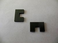
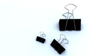
Interlocking calibration clips with curved and straight features for calibrating two filaments to each other. These clips work for calibrating multiple filaments on a single or dual extruder system. They can also be used to calibrate a single filament to itself.
If you are designing a multi-part assembly and need things to fit together these are the clips to use to determine the physical and thermal properties of your filaments.
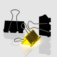
The clips have a 0.2mm gap between straight parts and a 0.25mm gap on curved features. This allows for the 0.1mm tolerance that most printers and machining operations can hold to and results in a feature fit between parts with about 4 thousands of an inch clearance.
Testing of the clips is accomplished by printing the set found in the single STL file and flipping one of the clips upside down on top of the other to test the fit of the features. If the clips are loose then you are under extruding and need to lower the nominal diameter of the filament or increase the extrusion multiplier. If the clips are too tight then you are over extruding and need to increase the nominal diameter of the filament or decrease the extrusion multiplier. When the clips fit easily together with no wiggle and stay put you have precisely calibrated filament.
Note in the images that one filament calibrated with a nominal filament diameter of 1.66 and a melt temperature of 220 C while the other calibrated at 1.74 and a temperature of 215 C. Both of these are different than the physical measured diameters. Yet both filaments produce matching precision parts while being extruded from identically micro stepped extruders. This is the whole point of calibrating to the thermal properties of a filament.
The last two images show how to find the optimal melting temperature. By extruding out a constant stream of filament you should get a rope like coil with a vertical strand to the nozzle. It will stay this way when you stop the extrusion. I call them cobras because that is what they remind me of. If the filament is too cold it will pig tail and curl under the nozzle. Increase the temp 5 C. If the filament is too hot the vertical part will lean over and spider web as it sags when you stop the extrusion. Drop the temp 5 C. With a good melt temperature you have a +/- 5C range for adjustments to counter oozing (lower the temp) and perimeter gaps (increase the temp).
If you are designing a multi-part assembly and need things to fit together these are the clips to use to determine the physical and thermal properties of your filaments.
The clips have a 0.2mm gap between straight parts and a 0.25mm gap on curved features. This allows for the 0.1mm tolerance that most printers and machining operations can hold to and results in a feature fit between parts with about 4 thousands of an inch clearance.
Testing of the clips is accomplished by printing the set found in the single STL file and flipping one of the clips upside down on top of the other to test the fit of the features. If the clips are loose then you are under extruding and need to lower the nominal diameter of the filament or increase the extrusion multiplier. If the clips are too tight then you are over extruding and need to increase the nominal diameter of the filament or decrease the extrusion multiplier. When the clips fit easily together with no wiggle and stay put you have precisely calibrated filament.
Note in the images that one filament calibrated with a nominal filament diameter of 1.66 and a melt temperature of 220 C while the other calibrated at 1.74 and a temperature of 215 C. Both of these are different than the physical measured diameters. Yet both filaments produce matching precision parts while being extruded from identically micro stepped extruders. This is the whole point of calibrating to the thermal properties of a filament.
The last two images show how to find the optimal melting temperature. By extruding out a constant stream of filament you should get a rope like coil with a vertical strand to the nozzle. It will stay this way when you stop the extrusion. I call them cobras because that is what they remind me of. If the filament is too cold it will pig tail and curl under the nozzle. Increase the temp 5 C. If the filament is too hot the vertical part will lean over and spider web as it sags when you stop the extrusion. Drop the temp 5 C. With a good melt temperature you have a +/- 5C range for adjustments to counter oozing (lower the temp) and perimeter gaps (increase the temp).
Similar models
thingiverse
free
3D Printer Calibration Piece by JP1
...com/thing:4579156
the tighter tolerance clips will allow you to use designs with 0.1mm clearances between flat assembly surfaces.
thingiverse
free

Tight Tolerance Calibration Clips by JP1
...clearances between flat assembly surfaces can be used with similar results to what these clips will give you. you...
thingiverse
free

Extruder Calibration (Part Fitting) Test by jonnieZG
...ound em value to 3 decimals.
update 2017-09-06
added a groove on the top of both parts, in order to identify correct orientation.
thingiverse
free

50mm Test Square by Menneset
...e extruder is too cold and/or print speed is too fast. (also check for partially clogged extruder and moisture/dirt in filament.)
thingiverse
free
Simplify3d Extrusion Multiplier Calibration Cube
...the lines are rough (too much material extruded on direction change) reduce the multiplier in 0.01 or 0.02 increments and repeat.
grabcad
free

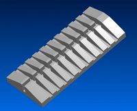
High Temp Calibration Tower
...high temp calibration tower
grabcad
calibration tower higher temperature filaments.
3 degree c x 10mm increments.
thingiverse
free

Calibration tower by peke
...passed all these tests ... maybe it will become your favorite clipboard or will decorate tastefully the bottom of your trash can.
thingiverse
free
Filament Extrusion Measurement Rig by brunofporto
...e to put a piece or lenght of 4mm od ptfe tube and better clearance for the filament. also two versions with 100mm and 125mm gap!
grabcad
free

MakerBot PLA Filament Spool
...-149°f);
melting temp: 150-160°c (302-320°f);
nozzle temp: 230°c (446°f)
diameter 1.75 mm
filament diameter 0.07 in
weight 2 lb
thingiverse
free

Extruder calibration tool by wylekyot
...m from end. so i clip it on make a mark and remove it. then run 100mm of filament. it is made for 3mm(2.85mm) filament diameter.
Jp1
turbosquid
$18
jp1
... available on turbo squid, the world's leading provider of digital 3d models for visualization, films, television, and games.
thingiverse
free
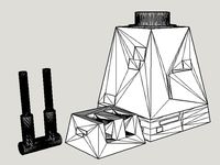
Mod of JP1's Death Star Turret for Lego by ICanMakingThings
...nclude a destroyed turret conversion. it opens up all sorts of options. find it here... http://www.thingiverse.com/make:178576
thingiverse
free

RBB3-XL Name Plate by JP1
...our own front plates this name plate replaces the reliabuild 3d name plate found here: https://www.thingiverse.com/thing:2096308
thingiverse
free
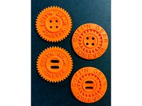
BUTToN GEAR FOREVER by JP1
...
https://www.thingiverse.com/thing:1037301https://www.thingiverse.com/thing:2502677
a good part cooling fan helps as well.
enjoy!
thingiverse
free

Ammo clip loader Pin by JP1
....
the stl file is cura scaled and oriented for printing. note the printing instructions to get a strong accurately printed part.
thingiverse
free
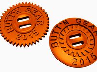
BUTToN GEAR by JP1
...and a button installed on a boot.
for further details see the original style post here: http://www.thingiverse.com/thing:1117591
thingiverse
free

Spool Hub - 56mm to 8mm by JP1
...include the source file with object units in mm and scene units in inches. the cs file is cura scaled and oriented for printing.
thingiverse
free

ID Badge Holder by JP1
... is extra security to keep the two parts together when strapped to your arm.
the parts are cura scaled and oriented for printing.
thingiverse
free

Can Handle - High Resolution by JP1
...ted in pla but i would not leave it in a hot car when using that material.
the stl file is cura scaled and oriented for printing.
thingiverse
free

Spool Hub 54mm x 8mm with tapered shims by JP1
...ated filament for best results using the clip system found here:http://www.thingiverse.com/thing:1037301
print two of these hubs.
Interlocking
turbosquid
$29
Modular Interlocking Blocks
...modular interlocking blocks for download as max, obj, and fbx on turbosquid: 3d models for games, architecture, videos. (1149913)
turbosquid
$8
Interlocking Wooden Swirls Coffee Table
...g wooden swirls coffee table for download as ma, obj, and fbx on turbosquid: 3d models for games, architecture, videos. (1270093)
turbosquid
$29
Gucci Interlocking Stainless Steel Watch
... available on turbo squid, the world's leading provider of digital 3d models for visualization, films, television, and games.
turbosquid
$8

Two Piece Interlocking Sliding Coffee Table
...locking sliding coffee table for download as ma, obj, and fbx on turbosquid: 3d models for games, architecture, videos. (1263767)
3d_export
$10

Q Chair 3D Model
...q chair 3d model 3dexport chair interlocking plastic modern contemporary bench modular q chair 3d model...
3d_export
$5

Red Card Table Lamp 3D Model
...table lamp 3d model
3dexport
interlock sheet red gloss metal plastic indigo
red card table lamp 3d model kimo25489 88892 3dexport
3d_export
$10

Crowd Barrier 3D Model
...mills management public event no access safety hazard entry interlocking steel crowd barrier 3d model download .c4d .max .obj...
3ddd
free
Jigsaw Puzzle Stools
...unwrap-развертке. made of hand-carved mango wood from india, these interlocking puzzle stools function as occasional seating, coffee tables, benches...
3d_export
free
karbandi
...it can bear many weight because of the special form and geometric column.<br>dimension: 200mm * 200mm<br>100mm height
3ddd
$1

MOVISI - play - shelving system
...often as you like. you can even design entire room dividers with alleys to walk through.
design: [b]antoine phelouza[/b]t"
Calibration
turbosquid
$15

DEFIBRILLATOR CALIBRATORS
... available on turbo squid, the world's leading provider of digital 3d models for visualization, films, television, and games.
turbosquid
$3
Calibration Test Benches
...libration test benches for download as 3ds, obj, c4d, and fbx on turbosquid: 3d models for games, architecture, videos. (1355804)
turbosquid
$79
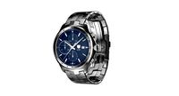
Tag Heuer Monaco Calibre 11
...free 3d model tag heuer monaco calibre 11 for download as max on turbosquid: 3d models for games, architecture, videos. (1634427)
turbosquid
$50
Smith & Wesson 50 Calibre Magnum
... available on turbo squid, the world's leading provider of digital 3d models for visualization, films, television, and games.
3d_export
$10
Laboratory Calibration Weight Set 1 3D Model
... 3d model
3dexport
laboratory lab science equipment weight set
laboratory calibration weight set 1 3d model bessoo 88084 3dexport
3d_export
$15
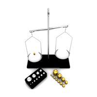
Laboratory Scale and Calibration Weight Set 3D Model
...port
laboratory lab science equipment weight set scale
laboratory scale and calibration weight set 3d model bessoo 88203 3dexport
3d_export
$5
3D printer filament calibration tool 3D Model
...ernier
3d printer filament calibration tool 3d model download .c4d .max .obj .fbx .ma .lwo .3ds .3dm .stl locoman 107942 3dexport
3d_export
$59
tag heuer link calibre 16 watch
...built to real-world scale. units used: centimeters. model is 18 centimeters tall.<br>scene objects are organized by groups.
3d_export
free
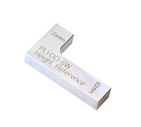
laser height reference calibration tool opt lasers
...ind out more about the engraving and cutting laser heads, this item was designed to work with, take a look at the following page:
3d_export
$99
Patek Philippe White Gold Calibre 89
...br>please note: this 3d model like all my other models cannot be used as nft, as is or modified<br>thank you for reading
Straights
3d_ocean
$5
truss quattro straight
...truss quattro straight
3docean
quattro straight truss
truss quattro straight
turbosquid
$25
Straight Line BearBrick Straight Line BearBrick
...ck straight line bearbrick for download as 3ds, max, and fbx on turbosquid: 3d models for games, architecture, videos. (1340992)
turbosquid
$2
Straight necklace
...uid
royalty free 3d model straight necklace for download as on turbosquid: 3d models for games, architecture, videos. (1651136)
turbosquid
$8

Straight Razor
...uid
royalty free 3d model straight razor for download as ztl on turbosquid: 3d models for games, architecture, videos. (1287737)
turbosquid
$9
Straight Razor
...d model straight razor for download as fbx, dae, obj, and stl on turbosquid: 3d models for games, architecture, videos. (1609423)
turbosquid
$5
tower straight
... available on turbo squid, the world's leading provider of digital 3d models for visualization, films, television, and games.
turbosquid
free
straight tee
... available on turbo squid, the world's leading provider of digital 3d models for visualization, films, television, and games.
turbosquid
$29

Straight chisels
...ight chisels for download as max, 3ds, dae, dwg, fbx, and obj on turbosquid: 3d models for games, architecture, videos. (1601842)
turbosquid
$7
Straight Cannon
...t cannon for download as blend, blend, 3ds, dae, fbx, and obj on turbosquid: 3d models for games, architecture, videos. (1600223)
3ddd
free
Armourcoat Flow Straight
...flow straight
3ddd
armourcoat , панель
гипсовая 3d панель flow straight
фирмы armourcoat
Curves
3d_export
free
curved sword
...curved sword
3dexport
a curved sword
3ddd
$1
CURVE
...wave oscillates rhythmically across this rug.
hand knotted from tibetan wool, curve is available from stock in a range of sizes.
3ddd
$1
SYSTEMPOOL Serie Curve
..., serie curve , раковина
systempool serie curve
3ddd
$1
DIAMANTE Curved Bench
...diamante curved bench
3ddd
diamante curved bench скамья
diamante curved bench
3ddd
$1
Enne Curve Sofa
...enne curve sofa
3ddd
enne , curve
диван enne curve, размеры -h800x920x2350mm
design_connected
$27
Curve Sofa
...curve sofa
designconnected
living divani curve sofa computer generated 3d model. designed by lissoni, piero.
3d_export
$5
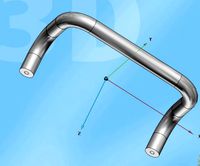
curve base handle
...curve base handle
3dexport
curve base handle
3d_export
$5
simple curve handle
...simple curve handle
3dexport
simple curve handle
turbosquid
$2
Curved leaf
...urbosquid
royalty free 3d model curved leaf for download as on turbosquid: 3d models for games, architecture, videos. (1641948)
turbosquid
$2

Curved Mouse
...rbosquid
royalty free 3d model curved mouse for download as on turbosquid: 3d models for games, architecture, videos. (1314525)
Clips
archibase_planet
free
Clip
...clip
archibase planet
paper-clip clip office equipment
clip band - 3d model for interior 3d visualization.
3d_export
$5
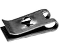
screw clip
...screw clip
3dexport
screw clip
3d_ocean
$4
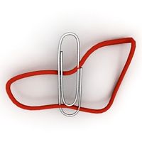
Butterfly clip
... a butterfly clip, it comes with a ready to render set for out of the box rendering. obj version and max alones version included.
turbosquid
$2

clip
...
royalty free 3d model clip for download as ma, obj, and fbx on turbosquid: 3d models for games, architecture, videos. (1358622)
turbosquid
$5

Clip
...lty free 3d model clip for download as c4d, 3ds, fbx, and obj on turbosquid: 3d models for games, architecture, videos. (1521355)
turbosquid
$19
Clip
... available on turbo squid, the world's leading provider of digital 3d models for visualization, films, television, and games.
turbosquid
$4
Clips
... available on turbo squid, the world's leading provider of digital 3d models for visualization, films, television, and games.
turbosquid
$3
clip
... available on turbo squid, the world's leading provider of digital 3d models for visualization, films, television, and games.
turbosquid
$2

clips
... available on turbo squid, the world's leading provider of digital 3d models for visualization, films, television, and games.
turbosquid
free

Clip
... available on turbo squid, the world's leading provider of digital 3d models for visualization, films, television, and games.